EP2389529B1 - Ventil, insbesondere für ein bauelement der mikrofluidtechnik - Google Patents
Ventil, insbesondere für ein bauelement der mikrofluidtechnik Download PDFInfo
- Publication number
- EP2389529B1 EP2389529B1 EP09810768.3A EP09810768A EP2389529B1 EP 2389529 B1 EP2389529 B1 EP 2389529B1 EP 09810768 A EP09810768 A EP 09810768A EP 2389529 B1 EP2389529 B1 EP 2389529B1
- Authority
- EP
- European Patent Office
- Prior art keywords
- channels
- valve according
- valve
- fluid
- separating film
- Prior art date
- Legal status (The legal status is an assumption and is not a legal conclusion. Google has not performed a legal analysis and makes no representation as to the accuracy of the status listed.)
- Active
Links
Images

Classifications
-
- F—MECHANICAL ENGINEERING; LIGHTING; HEATING; WEAPONS; BLASTING
- F16—ENGINEERING ELEMENTS AND UNITS; GENERAL MEASURES FOR PRODUCING AND MAINTAINING EFFECTIVE FUNCTIONING OF MACHINES OR INSTALLATIONS; THERMAL INSULATION IN GENERAL
- F16K—VALVES; TAPS; COCKS; ACTUATING-FLOATS; DEVICES FOR VENTING OR AERATING
- F16K99/00—Subject matter not provided for in other groups of this subclass
- F16K99/0001—Microvalves
-
- B—PERFORMING OPERATIONS; TRANSPORTING
- B01—PHYSICAL OR CHEMICAL PROCESSES OR APPARATUS IN GENERAL
- B01L—CHEMICAL OR PHYSICAL LABORATORY APPARATUS FOR GENERAL USE
- B01L3/00—Containers or dishes for laboratory use, e.g. laboratory glassware; Droppers
- B01L3/50—Containers for the purpose of retaining a material to be analysed, e.g. test tubes
- B01L3/502—Containers for the purpose of retaining a material to be analysed, e.g. test tubes with fluid transport, e.g. in multi-compartment structures
- B01L3/5027—Containers for the purpose of retaining a material to be analysed, e.g. test tubes with fluid transport, e.g. in multi-compartment structures by integrated microfluidic structures, i.e. dimensions of channels and chambers are such that surface tension forces are important, e.g. lab-on-a-chip
- B01L3/502738—Containers for the purpose of retaining a material to be analysed, e.g. test tubes with fluid transport, e.g. in multi-compartment structures by integrated microfluidic structures, i.e. dimensions of channels and chambers are such that surface tension forces are important, e.g. lab-on-a-chip characterised by integrated valves
-
- B—PERFORMING OPERATIONS; TRANSPORTING
- B01—PHYSICAL OR CHEMICAL PROCESSES OR APPARATUS IN GENERAL
- B01L—CHEMICAL OR PHYSICAL LABORATORY APPARATUS FOR GENERAL USE
- B01L3/00—Containers or dishes for laboratory use, e.g. laboratory glassware; Droppers
- B01L3/50—Containers for the purpose of retaining a material to be analysed, e.g. test tubes
- B01L3/502—Containers for the purpose of retaining a material to be analysed, e.g. test tubes with fluid transport, e.g. in multi-compartment structures
- B01L3/5027—Containers for the purpose of retaining a material to be analysed, e.g. test tubes with fluid transport, e.g. in multi-compartment structures by integrated microfluidic structures, i.e. dimensions of channels and chambers are such that surface tension forces are important, e.g. lab-on-a-chip
- B01L3/502746—Containers for the purpose of retaining a material to be analysed, e.g. test tubes with fluid transport, e.g. in multi-compartment structures by integrated microfluidic structures, i.e. dimensions of channels and chambers are such that surface tension forces are important, e.g. lab-on-a-chip characterised by the means for controlling flow resistance, e.g. flow controllers, baffles or throttle valves
-
- F—MECHANICAL ENGINEERING; LIGHTING; HEATING; WEAPONS; BLASTING
- F16—ENGINEERING ELEMENTS AND UNITS; GENERAL MEASURES FOR PRODUCING AND MAINTAINING EFFECTIVE FUNCTIONING OF MACHINES OR INSTALLATIONS; THERMAL INSULATION IN GENERAL
- F16K—VALVES; TAPS; COCKS; ACTUATING-FLOATS; DEVICES FOR VENTING OR AERATING
- F16K99/00—Subject matter not provided for in other groups of this subclass
- F16K99/0001—Microvalves
- F16K99/0003—Constructional types of microvalves; Details of the cutting-off member
- F16K99/0013—Rotary valves
-
- F—MECHANICAL ENGINEERING; LIGHTING; HEATING; WEAPONS; BLASTING
- F16—ENGINEERING ELEMENTS AND UNITS; GENERAL MEASURES FOR PRODUCING AND MAINTAINING EFFECTIVE FUNCTIONING OF MACHINES OR INSTALLATIONS; THERMAL INSULATION IN GENERAL
- F16K—VALVES; TAPS; COCKS; ACTUATING-FLOATS; DEVICES FOR VENTING OR AERATING
- F16K99/00—Subject matter not provided for in other groups of this subclass
- F16K99/0001—Microvalves
- F16K99/0003—Constructional types of microvalves; Details of the cutting-off member
- F16K99/0015—Diaphragm or membrane valves
-
- B—PERFORMING OPERATIONS; TRANSPORTING
- B01—PHYSICAL OR CHEMICAL PROCESSES OR APPARATUS IN GENERAL
- B01L—CHEMICAL OR PHYSICAL LABORATORY APPARATUS FOR GENERAL USE
- B01L2300/00—Additional constructional details
- B01L2300/08—Geometry, shape and general structure
- B01L2300/0809—Geometry, shape and general structure rectangular shaped
- B01L2300/0816—Cards, e.g. flat sample carriers usually with flow in two horizontal directions
-
- B—PERFORMING OPERATIONS; TRANSPORTING
- B01—PHYSICAL OR CHEMICAL PROCESSES OR APPARATUS IN GENERAL
- B01L—CHEMICAL OR PHYSICAL LABORATORY APPARATUS FOR GENERAL USE
- B01L2400/00—Moving or stopping fluids
- B01L2400/04—Moving fluids with specific forces or mechanical means
- B01L2400/0475—Moving fluids with specific forces or mechanical means specific mechanical means and fluid pressure
- B01L2400/0487—Moving fluids with specific forces or mechanical means specific mechanical means and fluid pressure fluid pressure, pneumatics
-
- B—PERFORMING OPERATIONS; TRANSPORTING
- B01—PHYSICAL OR CHEMICAL PROCESSES OR APPARATUS IN GENERAL
- B01L—CHEMICAL OR PHYSICAL LABORATORY APPARATUS FOR GENERAL USE
- B01L2400/00—Moving or stopping fluids
- B01L2400/06—Valves, specific forms thereof
- B01L2400/0633—Valves, specific forms thereof with moving parts
- B01L2400/0644—Valves, specific forms thereof with moving parts rotary valves
-
- B—PERFORMING OPERATIONS; TRANSPORTING
- B01—PHYSICAL OR CHEMICAL PROCESSES OR APPARATUS IN GENERAL
- B01L—CHEMICAL OR PHYSICAL LABORATORY APPARATUS FOR GENERAL USE
- B01L3/00—Containers or dishes for laboratory use, e.g. laboratory glassware; Droppers
- B01L3/56—Labware specially adapted for transferring fluids
- B01L3/567—Valves, taps or stop-cocks
-
- Y—GENERAL TAGGING OF NEW TECHNOLOGICAL DEVELOPMENTS; GENERAL TAGGING OF CROSS-SECTIONAL TECHNOLOGIES SPANNING OVER SEVERAL SECTIONS OF THE IPC; TECHNICAL SUBJECTS COVERED BY FORMER USPC CROSS-REFERENCE ART COLLECTIONS [XRACs] AND DIGESTS
- Y10—TECHNICAL SUBJECTS COVERED BY FORMER USPC
- Y10T—TECHNICAL SUBJECTS COVERED BY FORMER US CLASSIFICATION
- Y10T137/00—Fluid handling
- Y10T137/8593—Systems
- Y10T137/86493—Multi-way valve unit
- Y10T137/86501—Sequential distributor or collector type
-
- Y—GENERAL TAGGING OF NEW TECHNOLOGICAL DEVELOPMENTS; GENERAL TAGGING OF CROSS-SECTIONAL TECHNOLOGIES SPANNING OVER SEVERAL SECTIONS OF THE IPC; TECHNICAL SUBJECTS COVERED BY FORMER USPC CROSS-REFERENCE ART COLLECTIONS [XRACs] AND DIGESTS
- Y10—TECHNICAL SUBJECTS COVERED BY FORMER USPC
- Y10T—TECHNICAL SUBJECTS COVERED BY FORMER US CLASSIFICATION
- Y10T137/00—Fluid handling
- Y10T137/8593—Systems
- Y10T137/86493—Multi-way valve unit
- Y10T137/86863—Rotary valve unit
Definitions
- the invention relates to a valve, in particular for a component of the microfluidic technology, having surfaces for mutual contact, with displacement of the abutting surfaces mutually movable valve bodies, wherein in one of the contact surfaces channels for the inflow and outflow of a fluid and in the other contact surface a recess for the formation of a connection between the channels is provided.
- Miniaturized, suitable for flow control in the microfluidic valves such type are for example from the DE 102 27 593 B4 and the US 6,748,975 B2 known.
- the contact surfaces of the valve body of these known valves has a dual function. On the one hand, they seal the inlet channel against the outlet channel when the valve is closed. On the other hand, they ensure in each valve position for a seal of the valve against the environment.
- the latter function is of particular importance, since fluidic microcomponents, in particular flow cells, are used primarily for the investigation of polluting substances, for example pathogen-containing substances.
- a movable valve body to ensure the sealing function against the environment / environment always on the wetted Abut sealing surface and thus be firmly connected to a fluid processing component.
- This is disadvantageous in particular if the component processing the fluid is a disposable article or a disposable.
- multiple valves per disposable results in a significant overhead for the production of the movable valve body itself and for their fluid-tight attachment, for example, to a flow cell.
- the US 5,725,017 describes a valve of microfluidic technology with two mutually movable valve bodies, which bear against each other in the closed state of the valve. Depending on the pressure of the fluid passing through the valve, the one valve body is pressed more or less strongly against a flexible film which can be expanded into a cavity and is connected to the other valve body at its circumference.
- the invention has for its object to provide a new valve of the type mentioned above, which provides more safety in terms of environmental contamination with reduced manufacturing costs and / or in which not both valve body need to be part of a fluid processing device.
- the valve according to the invention which achieves this object is characterized in that a flexible release film which can be stretched into the recess to form the connection between the channels is arranged between the contact surfaces.
- the mutually facing contact surfaces of the valve body no longer exert an immediate sealing function. Accordingly, the requirement for the surface quality of the contact surfaces is reduced. Due to the inventive release film only one of the contact surfaces and thus only one of the valve body needs to come into contact with the fluid. The risk of contamination can be reduced.
- a movable valve body may, after use, without the risk of environmental contamination, e.g. be removed from a flow cell. This is also advantageous if the valve body has to be replaced for reasons of wear or to build up an alternative valve or switching configuration.
- the release film with the channels for the inflow and outflow having valve body is connected so that they are against the contact surface of the Stators can not be moved. Since associated with rubbing relative movements between the release film and one of the contact surfaces take place only on the side facing away from the fluid of the release film, you can not affect the tightness of the valve.
- one of the valve bodies forms a stationary stator and the separating film is connected to the stator.
- the other valve body is then movable alone against the stator and preferably forms a rotatable about an axis rotor or a translationally displaceable part.
- stator on the channels for the inflow and outflow of the fluid and the rotor on the recess.
- curved, for example, cylindrical abutment surfaces are possible, in the preferred embodiment they are flat surfaces, which in particular are perpendicular to the axis of rotation of the rotor.
- the separating film is preferably connected to one of the valve bodies, including the outlets of the channels.
- a sub-assembly of the valve comprising the separating film and one of the valve bodies can then already be completely fluid-tight as such.
- stator and the release film are an integral part of the micro device, in particular a flow cell, and the rotor is preferably part of a control device for the micro device.
- the release film can be ensured by the release film that even after disposal of the micro-component no harmful fluid enters the environment.
- valve body on a projecting, against the other valve body engageable guide bar, which ensures a reproducible relative movement of the valve body against each other.
- this guide web may be a projecting annular web which engages over an edge delimiting the contact surface of the other valve body.
- the cross section of the mouths of the channels may be larger or smaller than the cross section of the connection between the channels. In this case, even with large dimensional tolerances of the valve components ensure the proper functioning of the valve.
- the separating film can be deflected into the depression by the pressure of the fluid or / and by negative pressure on the side of the separating film facing away from the fluid.
- one of the valve bodies has a suction channel opening into the recess.
- the cross-section of the connection between the channels may be controllable by changing the pressure of the fluid, in which the recess offers sufficient leeway for different distances of the separating film.
- the depression in the direction of displacement of the abutment surfaces is longer than the distance between the mouths of the channels and varies, e.g. continuous or stepwise, in cross section.
- the average cross section of the connecting channel formed and thus the flow resistance of the channel can be changed and thereby regulate the flow rate at a given fluid pressure.
- the valve has a plurality of pairs, each having an inlet and an outlet for a fluid-forming channels.
- Each of the pairs may be associated with a separate recess or the pairs are selectively connectable via a single recess.
- a single, e.g. centrally located channel optionally connect to one of several other channels.
- a lubricant can be used between the separating film and the contact surface having the recess, wherein the contact surface and the relevant contact surface have indentations, e.g. May have grooves for receiving the lubricant.
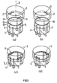
- a miniaturized valve suitable for controlling gas and liquid flows comprises a first valve body 1 forming a stator and a second, a valve body 2 forming a rotor.
- the rotor is rotatable about an axis 3 via a motor drive device (not shown).
- first valve body or stator 1 Through the first valve body or stator 1 lead two pairs of channels 4 and 5, each forming an inflow and outflow for a fluid and open in a second valve body or rotor 2 facing bearing surface 6.
- the flat, circular contact surface 6 of the stator is opposite a flat, to the contact surface 6 congruent contact surface 7 of the rotor.
- the contact surface 7 is bounded by an edge of the contact surface 6 cross annular web 8.
- two elongated, in a circular arc about the axis of rotation 3 extending recesses 9 are formed.
- the separating foil 10 which consists of a metal, plastic or composite material, can have a thickness of between 0.001 and 1 mm, depending on the size of the valve.
- FIGS. 1 A and 1 c shown rotational position of the rotor 2
- the mouths of the channels 4 and 5 are closed by the release film 10 and the overlying abutment surface 7 of the rotor 2.
- fluid under pressure in each case in one of the channels 4 and 5 can expand the separating film 10 into the recess 9 and thus create a flow connection 12 between the channels 4, 5, as shown in FIG Fig. 2a is shown.
- the rotor 2 advantageously remains separated from the fluid. By creating the fluid itself, dead spaces within the valve are avoided.
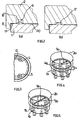
- the recess 9 is dimensioned in cross section so that a further margin for the expansion of the release film 10 into the recess 9 and thus for variations of the cross section of the flow connection 12 is.
- the flow rate can be varied within a wide adjustment range.
- Fig. 2b an only flat, the expansion of the release film even at low fluid pressure limiting recess 9 '. Further pressure increases in this case can only lead to a proportional increase in the flow rate.
- FIGS. 4 to 9 Reference is made where identical or equivalent parts are designated by the same reference numerals as in the preceding figures, wherein the relevant reference number of the letter a, b, etc. is attached.
- a valve with a stator 1a and a rotor 2a is a single serving as inflow or outflow for a fluid central channel 4a via a radially extending elongated recess 9a optionally with one of six, serving as inflow or outflow channels 5a connectable.
- FIG. 5 shows a valve with a stator 1 b and a rotor 2b, the stator 1 b has three pairs of diametrically opposite, each one inlet and outlet for forming a fluid channels 4b and 5b. According to this channel arrangement, an elongated recess 9b extends in the stator 2b almost over the entire length of the stator diameter.
- FIG. 6 shown valve with a stator 1 c and a rotor 2 c, the stator 1 c only two, an inlet and an outlet forming channels 4 c and 5 c.
- An elongated recess 9c extends along a circular arc around the rotation axis 3c of the rotor 2c.
- the arc length of the recess is greater than the corresponding arc length between the mouth openings of the channels 4c and 5c.
- the width and / or depth of the recess increases with the arc length.
- the (average) cross section of the respective connecting channel changes between the channels 4c and 5c. Accordingly, for a given fluid pressure, the flow rate depends solely on the rotational position of the rotor 2c.
- the rotor 2c can be rotated so that the flow rate varies between zero and a maximum amount.
- FIG. 7 shown valve with a stator 1d and a rotor 2d is different from the valve of Fig. 5 in that an elongated recess 9d is in communication with a vacuum passage 13 passing through the rotor 2d.
- the Cross-sectional size formed connecting channels thus not only depends on the pressure of the fluid but also from the negative pressure in the channel 13. The fluid pressure can be correspondingly low.
- An in Fig. 8 illustrated flow cell 14 has valves 15 and 16 with a rotor and a stator.
- the stator with a separating film 10e attached thereto is in each case an integral part of the flow cell 14 and in each case passes through two channels 4e and 5e or 4e 'and 5e' forming an inlet and an outlet.
- the rotor 2e or 2e ' may be part of an operating device for the flow cell and is placed upon insertion of the flow cell in the operating device on the respective, arranged above the stator region of the release film 10e. Flows within the flow cell 14 can be controlled by the valves 15 and 16, the structure of which is not described here in detail.
- Fig. 9 is another, in a flow cell 17 integrated valve 18 forth.
- a film 10 f arranged on a base plate 19 of the flow cell 17 is connected to the base plate 17, except in a circular area region 20.
- closed channels 4f and 5f are formed which, viewed in plan view of the flow cell, extend into the circular area region 20.
- a rotor 2f with a groove-like depression 9f can be placed on the flow cell as part of a (not shown) Betreibs réelles and controlled by the valve 18 through the channels 4f and 5f flowing fluid flow.
- substances enclosed in the flow cell remain enclosed in the flow cell even after disposal of the flow cell.
- the control gear does not come into contact with these substances.
- valves and microcomponents come in addition to metals, especially plastics such as COC, PE, PP, PMMA, possibly in combination with aluminum, into consideration.
- plastics the cost-effective injection molding process is expediently used.
- the Release film may be extruded, rolled and / or laminated.
- the injection film or another casting process can also be used for the release film.
- silicones, polyurethanes and thermoplastic elastomers come into consideration.
- the rotor can be machined and made of very strong plastics, such as POM, Teflon or other fluoroplastics, metals or ceramics.
- friction-reducing layers can be applied.
Landscapes
- Chemical & Material Sciences (AREA)
- Engineering & Computer Science (AREA)
- General Engineering & Computer Science (AREA)
- Dispersion Chemistry (AREA)
- Health & Medical Sciences (AREA)
- Mechanical Engineering (AREA)
- Analytical Chemistry (AREA)
- Chemical Kinetics & Catalysis (AREA)
- Clinical Laboratory Science (AREA)
- Hematology (AREA)
- General Health & Medical Sciences (AREA)
- Sliding Valves (AREA)
- Multiple-Way Valves (AREA)
Description
- Die Erfindung betrifft ein Ventil, insbesondere für ein Bauelement der Mikrofluidtechnik, mit Flächen zur gegenseitigen Anlage aufweisenden, unter Versatz der aneinander anliegenden Flächen gegeneinander bewegbaren Ventilkörpern, wobei in einer der Anlageflächen Kanäle für den Zu- und Abfluss eines Fluids ausmünden und in der anderen Anlagefläche eine Vertiefung für die Bildung einer Verbindung zwischen den Kanälen vorgesehen ist.
- Miniaturisierte, zur Strömungssteuerung in der Mikrofluidtechnik einsetzbare Ventile solcher Art sind beispielsweise aus der
DE 102 27 593 B4 und derUS 6,748,975 B2 bekannt. Den Anlageflächen der Ventilkörper dieser bekannten Ventile kommt eine Doppelfunktion zu. Sie dichten einerseits bei geschlossenem Ventil den Einlasskanal gegen den Auslasskanal ab. Andererseits sorgen sie in jeder Ventilstellung für eine Abdichtung des Ventils gegen die Umgebung. Letztere Funktion ist von besonderer Bedeutung, da fluidtechnische Mikrobauelemente, insbesondere Flusszellen, vorrangig zur Untersuchung umweltbelastender, z.B. Krankheitserreger enthaltender Substanzen eingesetzt werden. - Die Herstellung der Anlageflächen in der für die Dichtfunktion erforderlichen Qualität ist sehr aufwendig. Zahlreiche Anforderungen, darunter die Eignung zur Reibpaarung, schränken zudem die Möglichkeiten der Materialauswahl ein. Elastische, an sich zur Abdichtung geeignete Kunststoffe, die jedoch Weichmacher enthalten, scheiden in der Regel aus. Ebenso verbietet sich in den meisten Fällen der Gebrauch von Schmiermitteln zur Unterstützung der Dichtfunktion. So besteht vor allem bei längerer, die Dichtfunktion der Anlageflächen beeinträchtigender Nutzung der Ventile die Gefahr von Umweltkontaminationen.
- Ferner muss nach dem Stand der Technik ein beweglicher Ventilkörper zur Sicherstellung der Dichtfunktion gegenüber der Umgebung/Umwelt immer an der benetzten Dichtfläche anliegen und damit fest mit einem das Fluid verarbeitenden Bauteil verbunden sein. Dies ist insbesondere dann nachteilig, wenn es sich bei dem das Fluid verarbeitenden Bauteil um einen Einwegartikel oder ein Disposable handelt. Insbesondere bei mehreren Ventilen je Disposable ergibt sich ein erheblicher Mehraufwand für die Herstellung der beweglichen Ventilkörper selbst sowie für deren fluiddichte Anbringung z.B. an einer Flusszelle.
- Die
US 5,725,017 beschreibt ein Ventil der Mikrofluidtechnik mit zwei gegeneinander bewegbaren Ventilkörpern, die im geschlossenen Zustand des Ventils aneinander anliegen. Je nach Druck des durch das Ventil tretenden Fluids wird der eine Ventilkörper mehr oder weniger stark gegen eine flexible, in einen Hohlraum hinein ausdehnbare, an ihrem Ringumfang mit dem anderen Ventilkörper verbundene Folie gedrückt. - Der Erfindung liegt die Aufgabe zugrunde, ein neues Ventil der eingangs genannten Art zu schaffen, das bei verringertem Herstellungsaufwand mehr Sicherheit in Bezug auf Umweltkontaminationen bietet und/oder bei dem nicht beide Ventilkörper Bestandteil einer das Fluid verarbeitenden Einrichtung zu sein brauchen.
- Das diese Aufgabe lösende Ventil nach der Erfindung ist dadurch gekennzeichnet, dass zwischen den Anlageflächen eine flexible, unter Bildung der Verbindung zwischen den Kanälen in die Vertiefung hinein dehnbare Trennfolie angeordnet ist.
- Gemäß der Erfindung üben die einander zugewandten Anlageflächen der Ventilkörper keine unmittelbare Dichtfunktion mehr aus. Entsprechend verringert sich die Anforderung an die Oberflächenqualität der Anlageflächen. Durch die erfindungsgemöße Trennfolie braucht nur eine der Anlageflächen und damit nur einer der Ventilkörper mit dem Fluid in Berührung zu kommen. Die Kontaminationsgefahr lässt sich verringern.
- Ein beweglicher Ventilkörper kann nach Benutzung ohne die Gefahr einer Kontamination der Umgebung z.B. von einer Flusszelle entfernt werden. Dies ist auch von Vorteil, wenn der Ventilkörper aus Verschleißgründen oder zum Aufbau einer alternativen Ventil- bzw. Schaltkonfiguration ausgetauscht werden muss.
- Vorzugsweise ist die Trennfolie mit dem die Kanäle für den Zu- und Abfluss aufweisenden Ventilkörper verbunden, so dass sie sich gegen die Anlagefläche des Stators nicht verschieben lässt. Da mit Reibbeanspruchungen verbundene Relativbewegungen zwischen der Trennfolie und einer der Anlageflächen nur auf der dem Fluid abgewandten Seite der Trennfolie stattfinden, können Sie die Dichtigkeit des Ventils nicht beeinträchtigen.
- In einer besonders bevorzugten Ausführungsform der Erfindung bildet einer der Ventilkörper einen unbeweglichen Stator und die Trennfolie ist mit dem Stator verbunden. Der andere Ventilkörper ist dann allein gegen den Stator beweglich und bildet vorzugsweise einen um eine Achse drehbaren Rotor oder ein translatorisch verschiebbares Teil.
- Zweckmäßig weist in dieser Ausführungsform der Stator die Kanäle für den Zu- und Abfluss des Fluids und der Rotor die Vertiefung auf.
Während gekrümmte, z.B. zylindrische Anlageflächen möglich sind, handelt es sich in der bevorzugten Ausführungsform um ebene Flächen, die insbesondere senkrecht zur Drehachse des Rotors stehen. - Vorzugsweise ist die Trennfolie unter Einschluss der Ausmündungen der Kanäle mit einem der Ventilkörper verbunden. Eine die Trennfolie und einen der Ventilkörper umfassende Teilbaugruppe des Ventils kann dann bereits als solche vollkommen fluiddicht sein.
- Letzteres Merkmal ist insbesondere für eine Ausführungsform von Bedeutung, in welcher der Stator und die Trennfolie integraler Bestandteil des Mikrobauelements, insbesondere einer Flusszelle, sind und der Rotor vorzugsweise Bestandteil eines Betriebsgeräts für das Mikrobauelement ist. Vorteilhaft lässt sich durch die Trennfolie sichern, dass auch nach Entsorgung des Mikrobauelements kein schädliches Fluid in die Umwelt gelangt.
- Vorteilhaft weist einer der Ventilkörper einen vorstehenden, gegen den anderen Ventilkörper anlegbaren Führungssteg auf, der eine reproduzierbare Relativbewegung der Ventilkörper gegeneinander sichert. Im Falle eines Rotors kann es sich bei diesem Führungssteg um einen vorstehenden Ringsteg handeln, welcher einen die Anlagefläche des anderen Ventilkörpers begrenzenden Rand übergreift.
- Der Querschnitt der Ausmündungen der Kanäle kann größer oder kleiner als der Querschnitt der Verbindung zwischen den Kanälen sein. In diesem Fall lässt sich auch bei großen Maßtoleranzen der Ventilbauteile die ordnungsgemäße Funktion des Ventils sichern.
- Die Trennfolie lässt sich durch den Druck des Fluids oder/und durch Unterdruck auf der dem Fluid abgewandten Seite der Trennfolie in die Vertiefung hinein auslenken. Im letzteren Fall weist einer der Ventilkörper einen in der Vertiefung ausmündenden Saugkanal auf.
- Der Querschnitt der Verbindung zwischen den Kanälen kann durch Änderung des Drucks des Fluids steuerbar sein, in dem die Vertiefung genügend Spielraum für unterschiedlich weite Auslenkungen der Trennfolie bietet.
- In einer Ausführungsform der Erfindung ist die Vertiefung in Verschiebungsrichtung der Anlagenflächen länger als der Abstand zwischen den Ausmündungen der Kanäle und variiert, z.B. kontinuierlich oder stufenweise, im Querschnitt. Je nach Drehstellung lässt sich der mittlere Querschnitt des gebildeten Verbindungskanals und somit der Strömungswiderstand des Kanals verändern und dadurch bei gegebenem Fluiddruck die Durchflussmenge regulieren.
- In einer weiteren Ausführungsform der Erfindung weist das Ventil mehrere Paare, je einen Zu- und einen Abfluss für einen Fluid bildender Kanäle auf. Jedem der Paare kann eine gesonderte Vertiefung zugeordnet sein oder die Paare sind wahlweise über eine einzige Vertiefung verbindbar. Insbesondere lässt sich ein einziger, z.B. zentral gelegener Kanal wahlweise mit einem von mehreren weiteren Kanälen verbinden.
- Zur Unterstützung der Dichtfunktion lässt sich zwischen der Trennfolie und der die Vertiefung aufweisenden Anlagenfläche ein Schmiermittel einsetzen, wobei die Anlagefläche und die betreffende Anlagefläche Einbuchtungen, z.B. Riefen für die Aufnahme des Schmiermittels aufweisen kann.
- Die Erfindung wird im Folgenden anhand von Ausführungsbeispielen und der beiliegenden, sich auf diese Ausführungsbeispiele beziehenden Zeichnungen weiter erläutert. Es zeigen:
- Fig. 1
- ein erstes Ausführungsbeispiel für ein Ventil nach der Erfindung in der Offen- und Schließstellung, teilweise in Explosionsdarstellung,
- Fig. 2 und 3
- Detaildarstellungen verschiedener Varianten des Ventils von
Fig. 1 , - Fig. 4 bis 7
- weitere Ausführungsbeispiele für Ventile nach der Erfindung, und
- Fig. 8 und 9
- erfindungsgemäße, jeweils in eine Flusszelle integrierte Ventile nach der Erfindung.
- Ein miniaturisiertes, zur Steuerung von Gas- und Flüssigkeitsströmen geeignetes Ventil weist einen ersten, einen Stator bildenden Ventilkörper 1 und einen zweiten, einen Rotor bildenden Ventilkörper 2 auf. Der Rotor ist über eine (nicht gezeigte) Motorantriebseinrichtung um eine Achse 3 drehbar.
- Durch den ersten Ventilkörper bzw. Stator 1 führen zwei Paare von Kanälen 4 und 5, die jeweils einen Zufluss und einen Abfluss für ein Fluid bilden und in einer dem zweiten Ventilkörper bzw. Rotor 2 zugewandten Anlagefläche 6 ausmünden.
- Der ebenen, kreisrunden Anlagefläche 6 des Stators liegt eine ebene, zur Anlagefläche 6 deckungsgleiche Anlagefläche 7 des Rotors gegenüber. Die Anlagefläche 7 ist durch einen den Rand der Anlagefläche 6 übergreifenden Ringsteg 8 begrenzt. In der Anlagefläche 7 sind zwei längliche, in einem Kreisbogen um die Drehachse 3 verlaufende Vertiefungen 9 gebildet.
- Zwischen den Anlageflächen von Rotor und Stator befindet sich eine Trennfolie 10, die in dem gezeigten Ausführungsbeispiel deckungsgleich zu den Anlageflächen und in einem Randbereich 11 umlaufend unter Einschluss der Kanalausmündungen mit der Anlagefläche 6 des Stators 1 verschweißt ist. Die aus einem Metall, Kunststoff oder Verbundmaterial bestehende Trennfolie 10 kann je nach Größe des Ventils eine Dicke zwischen 0,001 und 1 mm aufweisen.
- In der in den
Figuren 1 a und 1 c gezeigten Drehstellung des Rotors 2 sind die Ausmündungen der Kanäle 4 und 5 durch die Trennfolie 10 und die darüber liegende Anlagefläche 7 des Rotors 2 verschlossen. In der Rotordrehstellung gemäßFig. 1 b und 1d kann hingegen in jeweils einem der Kanäle 4 und 5 unter Druck stehendes Fluid die Trennfolie 10 in die Vertiefung 9 hinein ausdehnen und so eine Strömungsverbindung 12 zwischen den Kanälen 4,5 schaffen, wie dies inFig. 2a dargestellt ist. Vorteilhaft bleibt dabei der Rotor 2 von dem Fluid getrennt. Indem sich das Fluid selbst seinen Weg schafft, werden Toträume innerhalb des Ventils vermieden. - Bei dem in
Fig. 2a gezeigten Ausführungsbeispiel ist die Vertiefung 9 im Querschnitt so bemessen, dass ein weiter Spielraum für die Ausdehnung der Trennfolie 10 in die Vertiefung 9 hinein und damit für Variationen des Querschnitts der Strömungsverbindung 12 besteht. Durch geringe Änderungen des Fluiddrucks lässt sich daher die Durchflussmenge in einem weiten Einstellbereich variieren. Alternativ zeigtFig. 2b eine nur flache, die Ausdehnung der Trennfolie schon bei geringem Fluiddruck begrenzende Vertiefung 9'. Weitere Drucksteigerungen können in diesem Fall nur zu einer proportionalen Erhöhung der Durchflussmenge führen. - Bei einer in
Fig. 3 gezeigten Variante des Ausführungsbeispiels vonFig. 1 ist die Breite zweier länglicher Vertiefungen 9" deutlich kleiner als der Durchmesser der Kanäle 4 und 5. Dadurch ist selbst bei großen Maßschwankungen der Ventilbauteile gesichert, dass in einer Stellung des Rotors Strömungsverbindungen zwischen den Kanälen 4,5 herstellbar sind. Alternativ könnte die Breite der länglichen Vertiefungen deutlich größer als der Durchmesser der Kanäle sein. - Es wird nun auf die weiteren
Figuren 4 bis 9 Bezug genommen, wo gleiche oder gleichwirkende Teile mit derselben Bezugszahl wie in den vorangehenden Figuren bezeichnet sind, wobei der betreffenden Bezugszahl der Buchstabe a,b usw. beigefügt ist. - Bei einem in
Fig. 4 gezeigten Ausführungsbeispiel für ein Ventil mit einem Stator 1a und einem Rotor 2a ist ein einziger als Zu- oder Abfluss für ein Fluid dienender zentraler Kanal 4a über eine sich radial erstreckende längliche Vertiefung 9a wahlweise mit einem von sechs, als Zu- oder Abfluss dienenden Kanälen 5a verbindbar. -
Figur 5 zeigt ein Ventil mit einem Stator 1 b und einem Rotor 2b, dessen Stator 1 b drei Paare diametral gegenüberliegender, jeweils einen Zu- und Abfluss für ein Fluid bildender Kanäle 4b und 5b aufweist. Entsprechend dieser Kanalanordnung erstreckt sich eine längliche Vertiefung 9b im Stator 2b nahezu über die gesamte Länge des Statordurchmessers. - Bei einem in
Fig. 6 gezeigten Ventil mit einem Stator 1 c und einem Rotor 2c weist der Stator 1 c nur zwei, einen Zu- und einen Abfluss bildende Kanäle 4c und 5c auf. Eine längliche Vertiefung 9c erstreckt sich entlang einem Kreisbogen um die Drehachse 3c des Rotors 2c. Die Bogenlänge der Vertiefung ist größer als die entsprechende Bogenlänge zwischen den Mündungsöffnungen der Kanäle 4c und 5c. Ferner nimmt die Breite oder/und Tiefe der Vertiefung mit der Bogenlänge zu. Je nach Drehstellung des Rotors 2c ändert sich der (mittlere) Querschnitt des jeweiligen Verbindungskanals zwischen den Kanälen 4c und 5c. Entsprechend hängt (bei gegebenem Fluiddruck) die Durchflussmenge allein von der Drehstellung des Rotors 2c ab. Der Rotor 2c kann so verdreht werden, dass die Durchflussmenge zwischen null und einer Maximalmenge variiert. - Ein in
Fig. 7 gezeigtes Ventil mit einem Stator 1d und einem Rotor 2d unterscheidet sich von dem Ventil vonFig. 5 dadurch, dass eine längliche Vertiefung 9d mit einem den Rotor 2d durchsetzenden Unterdruckkanal 13 in Verbindung steht. Die Querschnittsgröße gebildeter Verbindungskanäle hängt damit nicht nur vom Druck des Fluids sondern auch vom Unterdruck im Kanal 13 ab. Entsprechend gering kann der Fluiddruck sein. - Während die vorangehend anhand der
Figuren 4 bis 7 beschriebenen Ventile im Grundaufbau dem Ventil vonFig. 1 entsprechen, werden im Folgenden hiervon abweichende, in eine Flusszelle integrierte Ventile beschrieben. - Eine in
Fig. 8 dargestellte Flusszelle 14 weist Ventile 15 und 16 mit einem Rotor und einem Stator auf. Der Stator mit einer daran angebrachten Trennfolie 10e ist jeweils integraler Bestandteil der Flusszelle 14 und jeweils von zwei, einen Zu- und einen Abfluss bildenden Kanälen 4e und 5e bzw. 4e' und 5e' durchsetzt. Der Rotor 2e bzw. 2e' kann Bestandteil eines Betriebsgerätes für die Flusszelle sein und wird beim Einsetzen der Flusszelle in das Betriebsgerät auf den jeweiligen, über dem Stator angeordneten Bereich der Trennfolie 10e aufgesetzt. Durch die Ventile 15 und 16 lassen sich Strömungen innerhalb der Flusszelle 14 steuern, deren Aufbau hier im Einzelnen nicht weiter zu beschreiben ist. - Aus
Fig. 9 geht ein weiteres, in eine Flusszelle 17 integriertes Ventil 18 hervor. Eine auf einer Grundplatte 19 der Flusszelle 17 angeordnete Folie 10f ist, außer in einem Kreisflächenbereich 20, mit der Grundplatte 17 verbunden. Indem die Folie 10f Rillen in der Grundplatte 19 abdeckt, sind geschlossene Kanäle 4f und 5f gebildet, welche, in Draufsicht auf die Flusszelle gesehen, bis in den Kreisflächenbereich 20 hineinreichen. Dadurch sind einander diametral gegenüberliegende Ausmündungen gebildet. Ein Rotor 2f mit einer rillenartigen Vertiefung 9f kann als Bestandteil eines (nicht gezeigten) Betreibsgeräts auf die Flusszelle aufgesetzt und durch das Ventil 18 ein durch die Kanäle 4f und 5f fließender Fluidstrom gesteuert werden. - Vorteilhaft bleiben in der Flusszelle eingeschlossene Substanzen auch nach Entsorgung der Flusszelle in der Flusszelle eingeschlossen. Das Betriebsgerät kommt mit diesen Substanzen nicht in Berührung.
- Als Materialien für die vorangehend beschriebenen Ventile und Mikrobauelemente kommen neben Metallen vor allem Kunststoffe, wie z.B. COC, PE, PP, PMMA, ggf. in Kombination mit Aluminium, in Betracht. Bei Verwendung von Kunststoffen wird zweckmäßig das kostengünstige Spritzgießverfahren angewandt. Die Trennfolie kann extrudiert, gewalzt und/oder laminiert sein. Auch für die Trennfolie lässt sich das Spritzgieß- oder ein anderes Gießverfahren einsetzen. Neben den genannten Kunststoffen kommen, insbesondere für die Trennfolie, Silikone, Polyurethane sowie thermoplastische Elastomere in Betracht. Zur Verbindung der Trennfolie mit einem der Ventilkörper, z.B. mit dem Stator, kommt Heißsiegeln, Kleben, Laserschweißen sowie thermisches oder chemisches Bonden in Frage. Insbesondere der Rotor kann mechanisch bearbeitet sein und aus sehr festen Kunststoffen, wie POM, Teflon oder anderen Fluorkunststoffen, Metallen oder Keramik bestehen. Zur Bildung der Anlageflächen lassen sich reibungsmindernde Schichten auftragen.
- Hauptanwendungsgebiete der vorangehend beschriebenen Ventile bzw. Bauelemente sind die Bereitstellung, Verarbeitung und Analyse von Fluiden im Bereich der Medizin, insbesondere der medizinischen Diagnostik. Darüber hinaus kommen zahlreiche Einsatzmöglichkeiten in der Geräte- und Automatisierungstechnik, in den Bereichen Kosmetik, Umwelttechnik, Lebensmitteltechnik in Betracht. Aussichtsreich erscheint ferner der Einsatz in miniaturisierten Brennstoffzellen sowie in pneumatischen Steuerungssystemen.
Claims (18)
- Ventil, insbesondere für ein Bauelement (14,17) der Mikrofluidtechnik, mit Flächen (6,7) zur gegenseitigen Anlage aufweisenden, unter Verschiebung der Anlageflächen (6,7) gegeneinander bewegbaren Ventilkörpern (1,2), wobei in einer (6) der Anlageflächen (6,7) Kanäle (4,5) für den Zu- und Abfluss eines Fluids ausmünden und in der anderen Anlagefläche (7) eine Vertiefung (9) für die Bildung einer Verbindung (12) zwischen den Kanälen (4,5) vorgesehen ist,
dadurch gekennzeichnet,
dass zwischen den Anlageflächen (6,7) eine flexible, unter Bildung der Verbindung (12) in die Vertiefung (9) hinein dehnbare Trennfolie (10) angeordnet ist. - Ventil nach Anspruch 1,
dadurch gekennzeichnet,
dass die Trennfolie (10) mit dem die Kanäle (4,5) für den Zu- und Abfluss aufweisenden Ventilkörper (1) verbunden ist. - Ventil nach Anspruch 1 oder 2,
dadurch gekennzeichnet,
dass einer der Ventilkörper (6,7) einen unbeweglichen Stator (6) bildet und die Trennfolie (10) mit dem Stator (6) verbunden ist. - Ventil nach Anspruch 3,
dadurch gekennzeichnet,
dass der Stator (6) die Kanäle (4,5) für den Zu- und Abfluss des Fluids aufweist. - Ventil nach Anspruch 3 oder 4,
dadurch gekennzeichnet,
dass der andere Ventilkörper einen um eine Achse (3) drehbaren Rotor (2) oder ein translatorisch verschiebbares Teil bildet. - Ventil nach Anspruch 5,
dadurch gekennzeichnet,
dass die Anlageflächen (6,7) ebene Flächen sind, die insbesondere senkrecht zur Drehachse (3) des Rotors (2) stehen. - Ventil nach einem der Ansprüche 1 bis 6,
dadurch gekennzeichnet,
dass die Trennfolie (10) unter Einschluss der Ausmündungen der Kanäle (4,5) mit einem der Ventilkörper (1) verbunden ist. - Ventil nach einem der Ansprüche 1 bis 7,
dadurch gekennzeichnet,
dass einer (2) der Ventilkörper (1,2) einen vorstehenden, gegen den anderen Ventilkörper (1) anlegbaren Führungssteg aufweist, der insbesondere als Ringsteg (8) ausgebildet ist. - Ventil nach einem der Ansprüche 1 bis 8,
dadurch gekennzeichnet,
dass der Querschnitt der Ausmündungen der Kanäle (4,5) größer oder kleiner als der Querschnitt der Verbindung (12) zwischen den Kanälen (4,5) ist. - Ventil nach einem der Ansprüche 1 bis 9,
dadurch gekennzeichnet,
dass die Trennfolie (10) durch den Druck des Fluids oder/und durch Unterdruck auf der dem Fluid abgewandten Seite der Trennfolie (10) in die Vertiefung (9) hinein dehnbar ist. - Ventil nach einem der Ansprüche 1 bis 10,
dadurch gekennzeichnet,
dass der Querschnitt der Verbindung (12) zwischen den Kanälen (4,5) durch Änderung des Drucks des Fluids steuerbar ist. - Ventil nach einem der Ansprüche 1 bis 11,
dadurch gekennzeichnet,
dass der durch Fluiddruck beeinflussbare Querschnitt der Verbindung (12) zwischen den Kanälen (4,5) durch die Querschnittsabmessungen der Vertiefung (9) begrenzt oder begrenzbar ist. - Ventil nach einem der Ansprüche 1 bis 12,
dadurch gekennzeichnet,
dass die Vertiefung (9) in Verschiebungsrichtung der Anlageflächen länger als der Abstand zwischen den Ausmündungen der Kanäle (4,5) ist und im Querschnitt variiert. - Ventil nach einem der Ansprüche 1 bis 13,
dadurch gekennzeichnet,
dass mehrere Paare, je einen Zu- und einen Abfluss für ein Fluid bildender Kanäle (4,5) vorgesehen sind. - Ventil nach Anspruch 14,
dadurch gekennzeichnet,
dass die Kanäle (4,5) der Paare über gesonderte Vertiefungen oder wahlweise über eine einzige Vertiefung verbindbar sind. - Ventil nach Anspruch 14 oder 15,
dadurch gekennzeichnet,
dass ein Kanal (4a) wahlweise mit einem von mehreren weiteren Kanälen (5a) verbindbar ist. - Ventil nach einem der Ansprüche 1 bis 16,
dadurch gekennzeichnet,
dass zwischen der Trennfolie (10) und der die Vertiefung (9) aufweisenden Anlagefläche (7) ein Schmiermittel vorgesehen und vorzugsweise in der Trennfolie oder/und der Anlagefläche Einbuchtungen für die Aufnahme des Schmiermittels vorgesehen sind. - Ventil nach einem der Ansprüche 1 bis 17,
dadurch gekennzeichnet,
dass der Stator und die Trennfolie integraler Bestandteil des Bauelements, insbesondere einer Flusszelle (14,17), sind und der Rotor vorzugsweise Bestandteil eines Betriebsgeräts für das Mikrobauelement ist.
Applications Claiming Priority (2)
| Application Number | Priority Date | Filing Date | Title |
|---|---|---|---|
| DE200910005874 DE102009005874A1 (de) | 2009-01-21 | 2009-01-21 | Ventil, insbesondere für ein Bauelement der Mikrofluidtechnik |
| PCT/DE2009/001795 WO2010083795A1 (de) | 2009-01-21 | 2009-12-16 | Ventil, insbesondere für ein bauelement der mikrofluidtechnik |
Publications (2)
| Publication Number | Publication Date |
|---|---|
| EP2389529A1 EP2389529A1 (de) | 2011-11-30 |
| EP2389529B1 true EP2389529B1 (de) | 2016-03-30 |
Family
ID=42136017
Family Applications (1)
| Application Number | Title | Priority Date | Filing Date |
|---|---|---|---|
| EP09810768.3A Active EP2389529B1 (de) | 2009-01-21 | 2009-12-16 | Ventil, insbesondere für ein bauelement der mikrofluidtechnik |
Country Status (4)
| Country | Link |
|---|---|
| US (1) | US8960230B2 (de) |
| EP (1) | EP2389529B1 (de) |
| DE (1) | DE102009005874A1 (de) |
| WO (1) | WO2010083795A1 (de) |
Cited By (5)
| Publication number | Priority date | Publication date | Assignee | Title |
|---|---|---|---|---|
| US9662650B2 (en) | 2013-07-29 | 2017-05-30 | Atlas Genetics Limited | Fluidic cartridge and method for processing a liquid sample |
| US9816135B2 (en) | 2013-07-29 | 2017-11-14 | Atlas Genetics Limited | Fluidic cartridge for nucleic acid amplification and detection |
| US9908114B2 (en) | 2013-07-29 | 2018-03-06 | Atlas Genetics Limited | Cartridge, cartridge reader and method for preventing reuse of the cartridge |
| US9993818B2 (en) | 2013-07-29 | 2018-06-12 | Atlas Genetics Limited | Valve which depressurises, and a valve system |
| US9999883B2 (en) | 2013-07-29 | 2018-06-19 | Atlas Genetics Limited | System and method for processing fluid in a fluidic cartridge |
Families Citing this family (24)
| Publication number | Priority date | Publication date | Assignee | Title |
|---|---|---|---|---|
| FR2931838B1 (fr) | 2008-06-02 | 2010-06-11 | Millipore Corp | Installation pour traiter un liquide biologique. |
| FR2940145B1 (fr) * | 2008-12-24 | 2011-03-25 | Millipore Corp | Chariot et installation de traitement d'un liquide biologique |
| FR2941385B1 (fr) * | 2009-01-23 | 2011-04-01 | Millipore Corp | Procede pour fournir un circuit pour liquide biologique et circuit obtenu. |
| DE102009009728A1 (de) | 2009-02-19 | 2010-09-02 | Thinxxs Microtechnology Ag | Flusszelle mit integriertem Fluidspeicher |
| US9464319B2 (en) | 2009-03-24 | 2016-10-11 | California Institute Of Technology | Multivolume devices, kits and related methods for quantification of nucleic acids and other analytes |
| US10196700B2 (en) | 2009-03-24 | 2019-02-05 | University Of Chicago | Multivolume devices, kits and related methods for quantification and detection of nucleic acids and other analytes |
| US9415392B2 (en) | 2009-03-24 | 2016-08-16 | The University Of Chicago | Slip chip device and methods |
| US9447461B2 (en) | 2009-03-24 | 2016-09-20 | California Institute Of Technology | Analysis devices, kits, and related methods for digital quantification of nucleic acids and other analytes |
| FR2955119B1 (fr) | 2010-01-13 | 2012-12-28 | Millipore Corp | Circuit pour liquide biologique |
| FR2960796B1 (fr) | 2010-06-08 | 2014-01-24 | Millipore Corp | Dispositif pour une installation de traitement de liquide biologique |
| FR2960794B1 (fr) | 2010-06-08 | 2012-07-27 | Millipore Corp | Dispositif pour une installation de traitement de liquide biologique |
| FR2960795B1 (fr) | 2010-06-08 | 2012-07-27 | Millipore Corp | Dispositif pour une installation de traitement de liquide biologique |
| FR2961711B1 (fr) | 2010-06-23 | 2012-08-17 | Millipore Corp | Poche pour circuit d'une installation de traitement de liquide biologique |
| FR2961713B1 (fr) | 2010-06-23 | 2012-08-10 | Millipore Corp | Poche pour circuit d'une installation de traitement de liquide biologique |
| FR2963573B1 (fr) | 2010-08-03 | 2012-08-31 | Millipore Corp | Chariot de pompage pour une installation de traitement de liquide biologique |
| FR2973396B1 (fr) | 2011-03-28 | 2013-05-10 | Millipore Corp | Installation de traitement de liquide biologique |
| DE102012005270A1 (de) | 2012-03-10 | 2013-09-12 | Microfluidic Chipshop Gmbh | Vorrichtung zur Manipulation von Flüssigkeiten |
| FR2993572B1 (fr) | 2012-07-23 | 2016-04-15 | Emd Millipore Corp | Circuit pour liquide biologique comportant une vanne a pincement |
| US9610579B2 (en) | 2014-01-07 | 2017-04-04 | Daktari Diagnostics, Inc. | Fluid delivery devices, systems, and methods |
| US10527192B2 (en) | 2018-02-15 | 2020-01-07 | Talis Biomedical Corporation | Rotary valve |
| US11008627B2 (en) | 2019-08-15 | 2021-05-18 | Talis Biomedical Corporation | Diagnostic system |
| US12253497B2 (en) | 2022-02-23 | 2025-03-18 | Abb Schweiz Ag | Unitary distribution plate and configurable diaphragm |
| CN116139954B (zh) * | 2023-02-20 | 2023-08-22 | 首都医科大学 | 一种用于多通道等温扩增crispr检测的微流控芯片 |
| CN119972209B (zh) * | 2025-01-23 | 2025-12-02 | 重庆惠科金渝光电科技有限公司 | 套切母板的制作方法及套切母板 |
Family Cites Families (22)
| Publication number | Priority date | Publication date | Assignee | Title |
|---|---|---|---|---|
| US2613056A (en) * | 1947-11-13 | 1952-10-07 | Infilco Inc | Rotary disk valve |
| US3339583A (en) * | 1964-09-21 | 1967-09-05 | Lambert W Fleckenstein | Rotary diaphragm valve for water softeners |
| DE2447173C2 (de) * | 1974-10-03 | 1986-03-20 | Hansen-BTR GmbH, 3320 Salzgitter | Filtratablaufhahn |
| US4858883A (en) * | 1987-12-11 | 1989-08-22 | Integrated Fluidics, Inc. | Valve with flexible sheet member |
| US5265645A (en) * | 1988-10-28 | 1993-11-30 | Peerless Manufacturing Company | Surge reliever relief valve |
| JPH0674849B2 (ja) * | 1989-12-21 | 1994-09-21 | 竜 川辺 | 多方弁の開閉方法及び装置 |
| US5105851A (en) * | 1990-10-17 | 1992-04-21 | Hewlett-Packard Company | Apparatus for multi-path flow regulation |
| US5725017A (en) | 1997-01-27 | 1998-03-10 | Medtronic, Inc. | In-line pressure check valve for drug-delivery systems |
| US6453725B1 (en) * | 1999-01-07 | 2002-09-24 | Siemens Energy & Automation | Gas chromatograph sample and column-switching valve |
| US6470904B1 (en) * | 1999-09-24 | 2002-10-29 | California Institute Of Technology | Normally closed in-channel micro check valve |
| DE10123173A1 (de) * | 2001-05-12 | 2002-11-14 | Bosch Gmbh Robert | Ventil zum Steuern von Flüssigkeiten |
| US6702256B2 (en) | 2001-07-17 | 2004-03-09 | Agilent Technologies, Inc. | Flow-switching microdevice |
| US6748975B2 (en) | 2001-12-26 | 2004-06-15 | Micralyne Inc. | Microfluidic valve and method of manufacturing same |
| US7673650B2 (en) * | 2002-04-15 | 2010-03-09 | Jennings Jeffrey D | Sensitive fluid balancing relief valve |
| US6916113B2 (en) * | 2003-05-16 | 2005-07-12 | Agilent Technologies, Inc. | Devices and methods for fluid mixing |
| US6997213B1 (en) * | 2003-12-19 | 2006-02-14 | Uop Llc | Low cost plate assembly for rotary valve |
| CA2577824C (en) * | 2004-08-25 | 2012-02-07 | Systeme Analytique Inc. | Rotary valve and analytical chromatographic system using the same |
| WO2006056236A1 (en) * | 2004-11-25 | 2006-06-01 | Agilent Technologies, Inc. | Microfluidic arrangement with coupling device having a selectable optical detection portion |
| US7213547B2 (en) * | 2004-12-14 | 2007-05-08 | Massachusetts Institute Of Technology | Valve |
| US20070090321A1 (en) * | 2005-10-26 | 2007-04-26 | Toralf Bork | Dynamic hermetic barrier for use with implantable infusion pumps |
| JP4913470B2 (ja) * | 2006-04-26 | 2012-04-11 | 株式会社島津製作所 | 流路切換えバルブを用いた高速液体クロマトグラフ及び分析方法 |
| US8104506B2 (en) * | 2007-07-10 | 2012-01-31 | Mecanique Analytique Inc. | Diaphragm-sealed valve having intermediate communication ports |
-
2009
- 2009-01-21 DE DE200910005874 patent/DE102009005874A1/de not_active Withdrawn
- 2009-12-16 US US13/145,739 patent/US8960230B2/en active Active
- 2009-12-16 WO PCT/DE2009/001795 patent/WO2010083795A1/de not_active Ceased
- 2009-12-16 EP EP09810768.3A patent/EP2389529B1/de active Active
Cited By (5)
| Publication number | Priority date | Publication date | Assignee | Title |
|---|---|---|---|---|
| US9662650B2 (en) | 2013-07-29 | 2017-05-30 | Atlas Genetics Limited | Fluidic cartridge and method for processing a liquid sample |
| US9816135B2 (en) | 2013-07-29 | 2017-11-14 | Atlas Genetics Limited | Fluidic cartridge for nucleic acid amplification and detection |
| US9908114B2 (en) | 2013-07-29 | 2018-03-06 | Atlas Genetics Limited | Cartridge, cartridge reader and method for preventing reuse of the cartridge |
| US9993818B2 (en) | 2013-07-29 | 2018-06-12 | Atlas Genetics Limited | Valve which depressurises, and a valve system |
| US9999883B2 (en) | 2013-07-29 | 2018-06-19 | Atlas Genetics Limited | System and method for processing fluid in a fluidic cartridge |
Also Published As
| Publication number | Publication date |
|---|---|
| WO2010083795A1 (de) | 2010-07-29 |
| US20110297866A1 (en) | 2011-12-08 |
| US8960230B2 (en) | 2015-02-24 |
| EP2389529A1 (de) | 2011-11-30 |
| DE102009005874A1 (de) | 2010-07-22 |
Similar Documents
| Publication | Publication Date | Title |
|---|---|---|
| EP2389529B1 (de) | Ventil, insbesondere für ein bauelement der mikrofluidtechnik | |
| EP2576065B1 (de) | Flusszelle mit hohlraum und diaphragma | |
| EP3164212B1 (de) | Reagenzspeicher für fluide | |
| EP2304291B1 (de) | Mikroventil und abdichteinrichtung zur verwendung in einem mikrofluidiksystem sowie verfahren zu deren herstellung | |
| EP2304292B1 (de) | Mikroventil zur verwendung in einem mikrofluidiksystem sowie verfahren zu dessen herstellung | |
| AT519382B1 (de) | Vorrichtung mit Drehventil zur Manipulation von Flüssigkeiten | |
| EP1144095B1 (de) | Vorrichtung zum konzentrieren und/oder reinigen von makromolekülen in einer lösung und verfahren zum herstellen einer derartigen vorrichtung | |
| DE60103924T2 (de) | Mikrofluidische durchflussregelvorrichtung | |
| EP3225890B1 (de) | Mehrweghahn und verfahren zu dessen herstellung | |
| EP2531760A1 (de) | Mikrofluidisches bauelement zur handhabung eines fluids und mikrofluidischer chip | |
| EP2437890A1 (de) | Vorrichtung zum transportieren eines fluids in einem kanalstrang eines mikrofluidelements | |
| EP2248588B1 (de) | Montier- und demontierbares Mikrofluidiksystem und Verfahren zur Flutung des Systems | |
| DE102011078770A1 (de) | Mikrofluidische Vorrichtung, mikrofluidisches System und Verfahren zum Transport von Fluiden | |
| DE102011005811A1 (de) | Mikrofluidisches Ventil und mikrofluidische Plattform | |
| DE102014014964A1 (de) | Mehrwegeventil zur Steuerung von Flüssigkeitskreisen | |
| EP3884527B1 (de) | Transportvorrichtung mit aktor und trennschicht | |
| DE19622850B4 (de) | Lippendichtungsanordnung | |
| EP3406340B1 (de) | Flusszelle mit gehäusebauteil | |
| EP2775183A2 (de) | Mikrofluidisches Drehventil | |
| EP1078167B1 (de) | Mikroventil | |
| WO2010031559A1 (de) | Mikrofluidisches ventil, mikrofluidische pumpe, mikrofluidisches system und ein herstellungsverfahren | |
| DE102008056751A1 (de) | Fluidikvorrichtung mit normal-geschlossener Durchlassöffnung | |
| EP2754495A2 (de) | Mikrofluidisches Kanalsystem mit Blasenfängereinrichtung und Verfahren zum Entfernen von Gasblasen | |
| WO2012041479A1 (de) | Mikrofluidikchip mit mehreren zylinder-kolben-anordnungen | |
| EP0145859A2 (de) | Ventileinrichtung mit einem Piezoelektrischen oder magnetostroktiven Stellglied |
Legal Events
| Date | Code | Title | Description |
|---|---|---|---|
| PUAI | Public reference made under article 153(3) epc to a published international application that has entered the european phase |
Free format text: ORIGINAL CODE: 0009012 |
|
| 17P | Request for examination filed |
Effective date: 20110817 |
|
| AK | Designated contracting states |
Kind code of ref document: A1 Designated state(s): AT BE BG CH CY CZ DE DK EE ES FI FR GB GR HR HU IE IS IT LI LT LU LV MC MK MT NL NO PL PT RO SE SI SK SM TR |
|
| DAX | Request for extension of the european patent (deleted) | ||
| RIC1 | Information provided on ipc code assigned before grant |
Ipc: B01L 3/00 20060101ALI20150814BHEP Ipc: F16K 99/00 20060101AFI20150814BHEP |
|
| GRAP | Despatch of communication of intention to grant a patent |
Free format text: ORIGINAL CODE: EPIDOSNIGR1 |
|
| INTG | Intention to grant announced |
Effective date: 20150925 |
|
| GRAS | Grant fee paid |
Free format text: ORIGINAL CODE: EPIDOSNIGR3 |
|
| GRAA | (expected) grant |
Free format text: ORIGINAL CODE: 0009210 |
|
| AK | Designated contracting states |
Kind code of ref document: B1 Designated state(s): AT BE BG CH CY CZ DE DK EE ES FI FR GB GR HR HU IE IS IT LI LT LU LV MC MK MT NL NO PL PT RO SE SI SK SM TR |
|
| REG | Reference to a national code |
Ref country code: GB Ref legal event code: FG4D Free format text: NOT ENGLISH |
|
| REG | Reference to a national code |
Ref country code: CH Ref legal event code: EP |
|
| REG | Reference to a national code |
Ref country code: AT Ref legal event code: REF Ref document number: 785778 Country of ref document: AT Kind code of ref document: T Effective date: 20160415 |
|
| REG | Reference to a national code |
Ref country code: IE Ref legal event code: FG4D Free format text: LANGUAGE OF EP DOCUMENT: GERMAN |
|
| REG | Reference to a national code |
Ref country code: CH Ref legal event code: NV Representative=s name: ALDO ROEMPLER PATENTANWALT, CH |
|
| REG | Reference to a national code |
Ref country code: DE Ref legal event code: R096 Ref document number: 502009012367 Country of ref document: DE |
|
| REG | Reference to a national code |
Ref country code: LT Ref legal event code: MG4D |
|
| PG25 | Lapsed in a contracting state [announced via postgrant information from national office to epo] |
Ref country code: GR Free format text: LAPSE BECAUSE OF FAILURE TO SUBMIT A TRANSLATION OF THE DESCRIPTION OR TO PAY THE FEE WITHIN THE PRESCRIBED TIME-LIMIT Effective date: 20160701 Ref country code: NO Free format text: LAPSE BECAUSE OF FAILURE TO SUBMIT A TRANSLATION OF THE DESCRIPTION OR TO PAY THE FEE WITHIN THE PRESCRIBED TIME-LIMIT Effective date: 20160630 Ref country code: HR Free format text: LAPSE BECAUSE OF FAILURE TO SUBMIT A TRANSLATION OF THE DESCRIPTION OR TO PAY THE FEE WITHIN THE PRESCRIBED TIME-LIMIT Effective date: 20160330 Ref country code: FI Free format text: LAPSE BECAUSE OF FAILURE TO SUBMIT A TRANSLATION OF THE DESCRIPTION OR TO PAY THE FEE WITHIN THE PRESCRIBED TIME-LIMIT Effective date: 20160330 |
|
| REG | Reference to a national code |
Ref country code: NL Ref legal event code: MP Effective date: 20160330 |
|
| PG25 | Lapsed in a contracting state [announced via postgrant information from national office to epo] |
Ref country code: LT Free format text: LAPSE BECAUSE OF FAILURE TO SUBMIT A TRANSLATION OF THE DESCRIPTION OR TO PAY THE FEE WITHIN THE PRESCRIBED TIME-LIMIT Effective date: 20160330 Ref country code: SE Free format text: LAPSE BECAUSE OF FAILURE TO SUBMIT A TRANSLATION OF THE DESCRIPTION OR TO PAY THE FEE WITHIN THE PRESCRIBED TIME-LIMIT Effective date: 20160330 Ref country code: LV Free format text: LAPSE BECAUSE OF FAILURE TO SUBMIT A TRANSLATION OF THE DESCRIPTION OR TO PAY THE FEE WITHIN THE PRESCRIBED TIME-LIMIT Effective date: 20160330 |
|
| PG25 | Lapsed in a contracting state [announced via postgrant information from national office to epo] |
Ref country code: NL Free format text: LAPSE BECAUSE OF FAILURE TO SUBMIT A TRANSLATION OF THE DESCRIPTION OR TO PAY THE FEE WITHIN THE PRESCRIBED TIME-LIMIT Effective date: 20160330 |
|
| PG25 | Lapsed in a contracting state [announced via postgrant information from national office to epo] |
Ref country code: EE Free format text: LAPSE BECAUSE OF FAILURE TO SUBMIT A TRANSLATION OF THE DESCRIPTION OR TO PAY THE FEE WITHIN THE PRESCRIBED TIME-LIMIT Effective date: 20160330 Ref country code: PL Free format text: LAPSE BECAUSE OF FAILURE TO SUBMIT A TRANSLATION OF THE DESCRIPTION OR TO PAY THE FEE WITHIN THE PRESCRIBED TIME-LIMIT Effective date: 20160330 Ref country code: IS Free format text: LAPSE BECAUSE OF FAILURE TO SUBMIT A TRANSLATION OF THE DESCRIPTION OR TO PAY THE FEE WITHIN THE PRESCRIBED TIME-LIMIT Effective date: 20160730 |
|
| REG | Reference to a national code |
Ref country code: FR Ref legal event code: PLFP Year of fee payment: 8 |
|
| PG25 | Lapsed in a contracting state [announced via postgrant information from national office to epo] |
Ref country code: PT Free format text: LAPSE BECAUSE OF FAILURE TO SUBMIT A TRANSLATION OF THE DESCRIPTION OR TO PAY THE FEE WITHIN THE PRESCRIBED TIME-LIMIT Effective date: 20160801 Ref country code: RO Free format text: LAPSE BECAUSE OF FAILURE TO SUBMIT A TRANSLATION OF THE DESCRIPTION OR TO PAY THE FEE WITHIN THE PRESCRIBED TIME-LIMIT Effective date: 20160330 Ref country code: ES Free format text: LAPSE BECAUSE OF FAILURE TO SUBMIT A TRANSLATION OF THE DESCRIPTION OR TO PAY THE FEE WITHIN THE PRESCRIBED TIME-LIMIT Effective date: 20160330 Ref country code: SM Free format text: LAPSE BECAUSE OF FAILURE TO SUBMIT A TRANSLATION OF THE DESCRIPTION OR TO PAY THE FEE WITHIN THE PRESCRIBED TIME-LIMIT Effective date: 20160330 Ref country code: SK Free format text: LAPSE BECAUSE OF FAILURE TO SUBMIT A TRANSLATION OF THE DESCRIPTION OR TO PAY THE FEE WITHIN THE PRESCRIBED TIME-LIMIT Effective date: 20160330 Ref country code: CZ Free format text: LAPSE BECAUSE OF FAILURE TO SUBMIT A TRANSLATION OF THE DESCRIPTION OR TO PAY THE FEE WITHIN THE PRESCRIBED TIME-LIMIT Effective date: 20160330 |
|
| PG25 | Lapsed in a contracting state [announced via postgrant information from national office to epo] |
Ref country code: IT Free format text: LAPSE BECAUSE OF FAILURE TO SUBMIT A TRANSLATION OF THE DESCRIPTION OR TO PAY THE FEE WITHIN THE PRESCRIBED TIME-LIMIT Effective date: 20160330 |
|
| REG | Reference to a national code |
Ref country code: DE Ref legal event code: R097 Ref document number: 502009012367 Country of ref document: DE |
|
| PG25 | Lapsed in a contracting state [announced via postgrant information from national office to epo] |
Ref country code: DK Free format text: LAPSE BECAUSE OF FAILURE TO SUBMIT A TRANSLATION OF THE DESCRIPTION OR TO PAY THE FEE WITHIN THE PRESCRIBED TIME-LIMIT Effective date: 20160330 |
|
| PLBE | No opposition filed within time limit |
Free format text: ORIGINAL CODE: 0009261 |
|
| STAA | Information on the status of an ep patent application or granted ep patent |
Free format text: STATUS: NO OPPOSITION FILED WITHIN TIME LIMIT |
|
| 26N | No opposition filed |
Effective date: 20170103 |
|
| PG25 | Lapsed in a contracting state [announced via postgrant information from national office to epo] |
Ref country code: BE Free format text: LAPSE BECAUSE OF NON-PAYMENT OF DUE FEES Effective date: 20161231 Ref country code: SI Free format text: LAPSE BECAUSE OF FAILURE TO SUBMIT A TRANSLATION OF THE DESCRIPTION OR TO PAY THE FEE WITHIN THE PRESCRIBED TIME-LIMIT Effective date: 20160330 |
|
| PG25 | Lapsed in a contracting state [announced via postgrant information from national office to epo] |
Ref country code: MC Free format text: LAPSE BECAUSE OF FAILURE TO SUBMIT A TRANSLATION OF THE DESCRIPTION OR TO PAY THE FEE WITHIN THE PRESCRIBED TIME-LIMIT Effective date: 20160330 |
|
| REG | Reference to a national code |
Ref country code: IE Ref legal event code: MM4A |
|
| PG25 | Lapsed in a contracting state [announced via postgrant information from national office to epo] |
Ref country code: LU Free format text: LAPSE BECAUSE OF NON-PAYMENT OF DUE FEES Effective date: 20161216 |
|
| PG25 | Lapsed in a contracting state [announced via postgrant information from national office to epo] |
Ref country code: IE Free format text: LAPSE BECAUSE OF NON-PAYMENT OF DUE FEES Effective date: 20161216 |
|
| REG | Reference to a national code |
Ref country code: FR Ref legal event code: PLFP Year of fee payment: 9 |
|
| REG | Reference to a national code |
Ref country code: BE Ref legal event code: MM Effective date: 20161231 |
|
| PG25 | Lapsed in a contracting state [announced via postgrant information from national office to epo] |
Ref country code: HU Free format text: LAPSE BECAUSE OF FAILURE TO SUBMIT A TRANSLATION OF THE DESCRIPTION OR TO PAY THE FEE WITHIN THE PRESCRIBED TIME-LIMIT; INVALID AB INITIO Effective date: 20091216 Ref country code: CY Free format text: LAPSE BECAUSE OF FAILURE TO SUBMIT A TRANSLATION OF THE DESCRIPTION OR TO PAY THE FEE WITHIN THE PRESCRIBED TIME-LIMIT Effective date: 20160330 |
|
| PG25 | Lapsed in a contracting state [announced via postgrant information from national office to epo] |
Ref country code: TR Free format text: LAPSE BECAUSE OF FAILURE TO SUBMIT A TRANSLATION OF THE DESCRIPTION OR TO PAY THE FEE WITHIN THE PRESCRIBED TIME-LIMIT Effective date: 20160330 Ref country code: MK Free format text: LAPSE BECAUSE OF FAILURE TO SUBMIT A TRANSLATION OF THE DESCRIPTION OR TO PAY THE FEE WITHIN THE PRESCRIBED TIME-LIMIT Effective date: 20160330 |
|
| PG25 | Lapsed in a contracting state [announced via postgrant information from national office to epo] |
Ref country code: BG Free format text: LAPSE BECAUSE OF FAILURE TO SUBMIT A TRANSLATION OF THE DESCRIPTION OR TO PAY THE FEE WITHIN THE PRESCRIBED TIME-LIMIT Effective date: 20160330 |
|
| PG25 | Lapsed in a contracting state [announced via postgrant information from national office to epo] |
Ref country code: MT Free format text: LAPSE BECAUSE OF FAILURE TO SUBMIT A TRANSLATION OF THE DESCRIPTION OR TO PAY THE FEE WITHIN THE PRESCRIBED TIME-LIMIT Effective date: 20160330 |
|
| REG | Reference to a national code |
Ref country code: DE Ref legal event code: R081 Ref document number: 502009012367 Country of ref document: DE Owner name: THINXXS MICROTECHNOLOGY GMBH, DE Free format text: FORMER OWNER: THINXXS MICROTECHNOLOGY AG, 66482 ZWEIBRUECKEN, DE |
|
| REG | Reference to a national code |
Ref country code: AT Ref legal event code: HC Ref document number: 785778 Country of ref document: AT Kind code of ref document: T Owner name: THINXXS MICROTECHNOLOGY GMBH, DE Effective date: 20220628 |
|
| PGFP | Annual fee paid to national office [announced via postgrant information from national office to epo] |
Ref country code: DE Payment date: 20241210 Year of fee payment: 16 |
|
| PGFP | Annual fee paid to national office [announced via postgrant information from national office to epo] |
Ref country code: GB Payment date: 20241224 Year of fee payment: 16 |
|
| PGFP | Annual fee paid to national office [announced via postgrant information from national office to epo] |
Ref country code: FR Payment date: 20241223 Year of fee payment: 16 |
|
| PGFP | Annual fee paid to national office [announced via postgrant information from national office to epo] |
Ref country code: AT Payment date: 20241220 Year of fee payment: 16 |
|
| PGFP | Annual fee paid to national office [announced via postgrant information from national office to epo] |
Ref country code: CH Payment date: 20250101 Year of fee payment: 16 |