EP2389723B1 - Méthode pour le contrôle parallèle des transformateurs avec des changeurs de prise - Google Patents
Méthode pour le contrôle parallèle des transformateurs avec des changeurs de prise Download PDFInfo
- Publication number
- EP2389723B1 EP2389723B1 EP09777883.1A EP09777883A EP2389723B1 EP 2389723 B1 EP2389723 B1 EP 2389723B1 EP 09777883 A EP09777883 A EP 09777883A EP 2389723 B1 EP2389723 B1 EP 2389723B1
- Authority
- EP
- European Patent Office
- Prior art keywords
- current
- load
- parallel
- determined
- voltage
- Prior art date
- Legal status (The legal status is an assumption and is not a legal conclusion. Google has not performed a legal analysis and makes no representation as to the accuracy of the status listed.)
- Active
Links
Images



Classifications
-
- H—ELECTRICITY
- H02—GENERATION; CONVERSION OR DISTRIBUTION OF ELECTRIC POWER
- H02P—CONTROL OR REGULATION OF ELECTRIC MOTORS, ELECTRIC GENERATORS OR DYNAMO-ELECTRIC CONVERTERS; CONTROLLING TRANSFORMERS, REACTORS OR CHOKE COILS
- H02P13/00—Arrangements for controlling transformers, reactors or choke coils, for the purpose of obtaining a desired output
-
- H—ELECTRICITY
- H02—GENERATION; CONVERSION OR DISTRIBUTION OF ELECTRIC POWER
- H02J—ELECTRIC POWER NETWORKS; CIRCUIT ARRANGEMENTS OR SYSTEMS FOR SUPPLYING OR DISTRIBUTING ELECTRIC POWER; SYSTEMS FOR STORING ELECTRIC ENERGY
- H02J3/00—Circuit arrangements for AC mains or AC distribution networks
- H02J3/18—Arrangements for adjusting, eliminating or compensating reactive power in networks
- H02J3/1878—Arrangements for adjusting, eliminating or compensating reactive power in networks using tap changing or phase shifting transformers
-
- H—ELECTRICITY
- H02—GENERATION; CONVERSION OR DISTRIBUTION OF ELECTRIC POWER
- H02P—CONTROL OR REGULATION OF ELECTRIC MOTORS, ELECTRIC GENERATORS OR DYNAMO-ELECTRIC CONVERTERS; CONTROLLING TRANSFORMERS, REACTORS OR CHOKE COILS
- H02P13/00—Arrangements for controlling transformers, reactors or choke coils, for the purpose of obtaining a desired output
- H02P13/06—Arrangements for controlling transformers, reactors or choke coils, for the purpose of obtaining a desired output by tap-changing; by rearranging interconnections of windings
-
- Y—GENERAL TAGGING OF NEW TECHNOLOGICAL DEVELOPMENTS; GENERAL TAGGING OF CROSS-SECTIONAL TECHNOLOGIES SPANNING OVER SEVERAL SECTIONS OF THE IPC; TECHNICAL SUBJECTS COVERED BY FORMER USPC CROSS-REFERENCE ART COLLECTIONS [XRACs] AND DIGESTS
- Y02—TECHNOLOGIES OR APPLICATIONS FOR MITIGATION OR ADAPTATION AGAINST CLIMATE CHANGE
- Y02E—REDUCTION OF GREENHOUSE GAS [GHG] EMISSIONS, RELATED TO ENERGY GENERATION, TRANSMISSION OR DISTRIBUTION
- Y02E40/00—Technologies for an efficient electrical power generation, transmission or distribution
- Y02E40/30—Reactive power compensation
Definitions
- the invention relates to a method for parallel control of two or more parallel-connected step transformers whose ratio is set by a tap changer.
- the first method the so-called. Synchronization control
- Synchronization control can only be performed with transformers of the same voltage, power, short-circuit voltage, step voltage and number of stages. In these methods, all transformers of the respective parallel group must be in the same operating position.
- this method also known as the "master follower method" is the only method for the parallel control of single-phase transformers in a three-phase group.
- the second method operates according to the so-called. Circulating reactive current method.
- Such a method is from the DE 100 39 918 C2 known. It concerns a self-adapting power-factor control for minimizing circulating currents caused by parallel-connected three-phase transformers in networks.
- This known solution addresses the problem that in the voltage regulation of parallel-connected three-phase transformers, the unavoidable circulating currents, if they are not minimized, can lead to significant loads on the individual transformers and the grid.
- the DE 40 04 671 C1 relates to another method, which deals with the automatic computer-aided detection of the system configuration in a plurality of multi-stage at any number of busbars in parallel connected transformers and discloses a suitable method for their control.
- Each step transformer is assigned its own electronic controller.
- the type of parallel control described in the cited documents is mainly used in the parallel operation of transformers with different number of stages and different level voltages.
- a prerequisite is that each transformer in the parallel group is controlled by its own voltage regulator.
- a separate parallel control unit referred to in English as "Parallel Balancing Module” is required for each transformer.
- Such a method is z.
- the mentioned parallel control devices are in this case switched so that the self-adjusting circulating reactive current flows only via the built-in reactance of the respective parallel control device.
- the circulating reactive current is thus separated from the operating current and generated as a virtually purely inductive current to the reactance of the respective parallel control device, a current-proportional AC voltage, which is the phase of the actual voltage of the associated voltage regulator switched.
- a voltage monitoring device for reducing circulating reactive currents is known. This uses a method in which the circulating reactive currents are determined from the voltage and the current of each transformer. In this case, the process differentiates hiss transformers which are arranged in parallel at a place and transformers which are connected to each other via a network.
- Each tap changer has a digital controller.
- the digital controllers are connected to each other in a ring and exchange measurement and control values in order to keep the equalizing currents or circulating reactive currents flowing between the transformers to a minimum.
- each voltage regulator regulates to the same setpoint value so that the circulating reactive current reaches a minimum - hence the name of this procedure.
- This voltage deviation is increased by the switched AC voltage at the voltage regulator for the first transformer, but reduced in the voltage regulator for the second transformer, since the circulating reactive current flows here in the opposite direction.
- the switched AC voltage on the second transformer just compensates for the voltage change, so that its voltage regulator continues to operate with the voltage that would result without circulating reactive current.
- the voltage regulator of the first transformer works with twice the voltage deviation as without taking into account the circulating reactive current. As a result, the voltage regulators work towards each other until the circulating reactive current has reached a minimum. Whether or not the voltage regulators control the motor drives of the transformers in this case depends on the set sensitivity of the individual voltage regulators.
- the object of the invention is to provide a method for parallel control of the type mentioned, which makes no additional equipment required in addition to voltage regulators and can dispense with current-carrying cross-connections between transducers parallel-running transformers. It is another object of the invention to ensure by a corresponding method that taken from the parallel operation transformers do not affect the parallel operation of the remaining transformers and make no changes in the settings of the voltage regulator required.
- the method according to the invention is based on the general inventive idea of mathematically deriving all measured values previously determined by interconnection from the current or voltage transformers. This makes it possible to provide all necessary for controlling parallel-running transformers electrical parameters with very simple converter circuits. The wiring between the transducers and the respective voltage regulator is thus reduced to a minimum, so that even with a parallel control of transformers only one current and one voltage transformer for each transformer is needed.
- the method according to the invention is suitable for transformers with comparable rated power, rated voltage, short-circuit voltage and switching group, with the same or unequal step voltage.
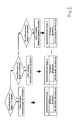
- FIG. 1 illustrated methods are explained in total. It consists of six individual process steps, numbered laterally.
- the phase shift ⁇ can be determined in the voltage regulator.
- Reactive current I X and active current I r can be detected vectorially with a current transformer and then calculated in the controller of the respective voltage regulator.
- the current transformer measures the load current I load n of the respective transformer n as apparent current.
- This method allows the use of different converter circuits in contrast to the known control method according to ANSI, which substantially increases the flexibility.
- each parallel-connected transformer is assigned its own voltage regulator and that all voltage regulators via a common data bus, z. B. CAN bus, are interconnected for information exchange.
- This so-called. CAN (Control Area Network) bus offers a high transmission speed with the simplest installation and maximum transmission reliability. All controllers can therefore exchange information with the other voltage regulators of the parallel-connected transformers.
- phase angle of the total current is determined from the collected measured values.
- phase angle at the load ⁇ load is determined solely by the electrical properties of the connected load.
- the individual desired reactive current from each controller is determined from its own active current and the tangent of the phase angle of the total current already determined in the previous method step.
- the voltage regulator knows the reactive current I X n required , which the load demands, and the contribution of the reactive current I X n , which supplies the "his" transformer thereto.
- This difference is a measure of the circulating reactive current and should be minimized by operating the multi-step control gear on the transformer.
- this controlled variable ⁇ I X n is converted into a voltage by means of a resistor.
- the height of this voltage is a measure of the deviation of the respective voltage regulator as well as the deviation from the algorithm of the actual voltage regulation.
- the voltage regulator will drive the on-load tap-changer to a position where the reactive current through the transformer is minimal.
- each voltage regulator regularly determines current values for the active current and the reactive current.
- FIG. 3 also shows a schematic representation of the third step of the method once again alone. It is clarified here how from the collected measured values of all controllers, ie as a result the transmitted active current and reactive current of all controllers by combining the corresponding values a total active current and a total reactive current determined and in turn results in the phase angle of the total current.
- FIG. 4 Finally, the last four steps of the method according to the invention are shown again in a schematic representation.
- the lateral numbering refers referring to the numbering in FIG. 1 for the individual steps of the complete method according to the invention.
- the setting is the voltage regulator, i. H. z. As control factor, sensitivity, etc., independent of the parallel operation.
- the function of the known in voltage regulators from the prior art LDC (Line Drop Compensation) is not affected.
- individual transformers can be removed at any time from the parallel operation or switched on again without disturbing the parallel operation of the remaining transformers.
- no changes of the specific settings on the voltage regulators are required.
- the inventive method allows in principle the parallel operation of transformers of different characteristics, such as rated power, number of stages and step voltage - within the limit of the highest permissible circular reactive current.
Landscapes
- Engineering & Computer Science (AREA)
- Power Engineering (AREA)
- Control Of Electrical Variables (AREA)
- Supply And Distribution Of Alternating Current (AREA)
Claims (1)
- Procédé de commande en parallèle de deux ou plusieurs transformateurs à prises, branchés en parallèle selon lequel :- un régulateur de tension propre est associé à chaque transformateur à prises et tous les régulateurs de tension sont reliés par un bus de données commun pour l'échange d'informations,- on détermine tout d'abord la valeur de mesure du courant actif et du courant réactif pour chacun des transformateurs à prises, branchés en parallèle,- ensuite, à partir de la somme de tous les courants actifs et de la somme de tous les courants réactifs de tous les transformateurs à prises, branchés en parallèle, on détermine l'angle de phase ϕ load du courant total qui s'établit,- ensuite, on détermine le courant réactif de consigne de chaque transformateur à prises, associé, à partir de son courant actif et de l'angle de phase ϕ load déterminé pour le courant total, et- ensuite on détermine le courant réactif en boucle à partir du courant réactif de consigne déterminé préalablement et du courant réactif propre,procédé caractérisé en ce qu'- on détermine des valeurs de mesure du courant actif et du courant réactif séparément dans chaque régulateur de tension associé et on transmet ces valeurs à tous les autres régulateurs de tension,- ensuite, on collecte ces valeurs de mesure de tous les transformateurs à prises, branchés en parallèle dans chacun des régulateurs de tension,- séparément, on détermine l'angle de phase ϕ load du courant total qui s'établit, le courant réactif de consigne et le courant réactif en boucle respectif dans chaque régulateur de tension,- pour déterminer l'angle de phase ϕ load du courant total qui s'établit, on détermine tout d'abord :- la somme des courants actifs ∑ Ir selon l'équation
 - la somme des courants réactifs ∑ Ix selon l'équation
 - on détermine l'angle de phase ϕ load selon les équations :
 - on détermine le courant réactif de consigne Ixnsoll de chaque régulateur avec le propre courant actif Im du transformateur à prises respectif et de la tangente de l'angle de phase ϕ load du courant total, et- enfin, on détermine l'équation de régulation avec son signe algébrique pour chaque régulateur de tension du transformateur à prises, associé et on génère un ordre d'actionnement pour minimiser l'écart de réglage.
Applications Claiming Priority (2)
| Application Number | Priority Date | Filing Date | Title |
|---|---|---|---|
| DE200810053193 DE102008053193A1 (de) | 2008-10-24 | 2008-10-24 | Verfahren zur Parallelsteuerung von Transformatoren mit Stufenschaltern |
| PCT/EP2009/005908 WO2010045995A2 (fr) | 2008-10-24 | 2009-08-14 | Procédé de commande en parallèle de transformateurs avec des commutateurs à gradins |
Publications (2)
| Publication Number | Publication Date |
|---|---|
| EP2389723A2 EP2389723A2 (fr) | 2011-11-30 |
| EP2389723B1 true EP2389723B1 (fr) | 2013-06-12 |
Family
ID=42041832
Family Applications (1)
| Application Number | Title | Priority Date | Filing Date |
|---|---|---|---|
| EP09777883.1A Active EP2389723B1 (fr) | 2008-10-24 | 2009-08-14 | Méthode pour le contrôle parallèle des transformateurs avec des changeurs de prise |
Country Status (3)
| Country | Link |
|---|---|
| EP (1) | EP2389723B1 (fr) |
| DE (1) | DE102008053193A1 (fr) |
| WO (1) | WO2010045995A2 (fr) |
Cited By (1)
| Publication number | Priority date | Publication date | Assignee | Title |
|---|---|---|---|---|
| US10193341B2 (en) | 2014-12-19 | 2019-01-29 | Maschinenfabrik Reinhausen Gmbh | Method of operating parallel transformers |
Families Citing this family (2)
| Publication number | Priority date | Publication date | Assignee | Title |
|---|---|---|---|---|
| CN103280304B (zh) * | 2013-07-01 | 2015-09-30 | 保定天威集团特变电气有限公司 | 一种变压器有载开关并联调压控制方法 |
| RU2740778C1 (ru) * | 2020-03-23 | 2021-01-21 | Федеральное государственное бюджетное образовательное учреждение высшего образования "Сибирский государственный университет науки и технологий имени академика М.Ф. Решетнева" (СибГУ им. М.Ф. Решетнева) | Способ параллельного включения двух трансформаторов |
Family Cites Families (5)
| Publication number | Priority date | Publication date | Assignee | Title |
|---|---|---|---|---|
| DE4004671C1 (en) * | 1990-02-15 | 1991-09-19 | Maschinenfabrik Reinhausen Gmbh, 8400 Regensburg, De | Automatically identifying installation configuration - using computer to cover stepped transformers coupled to bus=bars as desired and for regulation |
| DE4033391C2 (de) * | 1990-10-20 | 1994-06-09 | Reinhausen Maschf Scheubeck | Verfahren zur Parallellaufregelung von Stufentransformatoren |
| ATA29792A (de) * | 1992-02-19 | 1994-08-15 | Elin Energieversorgung | Anordnung zur spannungsregelung beim parallelbetrieb von transformatoren |
| DE10039918C2 (de) | 2000-08-16 | 2002-08-01 | Eberle A Gmbh | Selbstadaptierende Power-Factor-Regelung |
| GB2417376B (en) * | 2004-08-21 | 2008-11-26 | Jonathan Nicholas Hiscock | A voltage control scheme for high voltage power transformers |
-
2008
- 2008-10-24 DE DE200810053193 patent/DE102008053193A1/de not_active Withdrawn
-
2009
- 2009-08-14 EP EP09777883.1A patent/EP2389723B1/fr active Active
- 2009-08-14 WO PCT/EP2009/005908 patent/WO2010045995A2/fr not_active Ceased
Cited By (1)
| Publication number | Priority date | Publication date | Assignee | Title |
|---|---|---|---|---|
| US10193341B2 (en) | 2014-12-19 | 2019-01-29 | Maschinenfabrik Reinhausen Gmbh | Method of operating parallel transformers |
Also Published As
| Publication number | Publication date |
|---|---|
| WO2010045995A3 (fr) | 2011-05-26 |
| WO2010045995A2 (fr) | 2010-04-29 |
| EP2389723A2 (fr) | 2011-11-30 |
| DE102008053193A1 (de) | 2010-04-29 |
Similar Documents
| Publication | Publication Date | Title |
|---|---|---|
| DE3225285C2 (de) | Verfahren zum Betrieb einer Hochspannungs-Gleichstrom-Übertragungsanlage mit beliebig vielen Umformerstationen | |
| EP3417523B1 (fr) | Procédé de commande d'un transformateur de régulation et installation électrique de couplage de deux réseaux à courant alternatif | |
| EP3934931A1 (fr) | Station de charge pour charger des véhicules électriques | |
| AT504200B1 (de) | Verfahren zur regelung von wechselrichtern | |
| EP3235091B1 (fr) | Procédé de fonctionnement en parallèle sélectif pour appareils de mesure/commande | |
| EP2919352A1 (fr) | Procédé de fonctionnement d'un usager électrique, d'un point de mesure électrique sur un réseau d'usager électrique et usager électrique et point de mesure électrique | |
| EP0197329B1 (fr) | Procédé pour équilibrer des grandeurs électriques dans des fours à arc à courant triphasé et dispositif pour exécuter le procédé | |
| EP2864631A2 (fr) | Parc éolien comprenant plusieurs points d'alimentation du réseau | |
| DE19835857B4 (de) | Stromwandlervorrichtung | |
| DE102012100673A1 (de) | Vorrichtung zur elektrischen Energieeinspeisung aus einer dezentralen Eigenerzeugeranlage in ein Stromnetz | |
| DE102019129413A1 (de) | Kompensationsvorrichtung für Ableitströme | |
| DE102010040969A1 (de) | Transformator mit Einrichtung zur Aufaddierung einer Spannung | |
| DE69511498T2 (de) | Verfahren und Vorrichtung zur Steuerung einer Anlage zur Übertragung von Hochspannungsgleichstrom | |
| DE112022002486T5 (de) | Einstellung der umrichterklemmenspannung in leistungssystem | |
| EP2389723A2 (fr) | Procédé de commande en parallèle de transformateurs avec des commutateurs à gradins | |
| DE4004671C1 (en) | Automatically identifying installation configuration - using computer to cover stepped transformers coupled to bus=bars as desired and for regulation | |
| EP3759783A1 (fr) | Dispositif de connexion d'un réseau partiel à un réseau à tension alternative et procédé de commande d'une sortie électrique | |
| DE102017201734B4 (de) | Ladegerät und Verfahren zur Reduzierung der Schieflast eines zweiphasigen Ladegeräts | |
| DE102012103735A1 (de) | Erdschluss-System | |
| EP3447602B1 (fr) | Procédé et dispositif de commande de réglage de la tension d'un système de transformateur | |
| EP3068006A1 (fr) | Commande d'eolienne /de parc eolien et procede de commande | |
| EP0823715B1 (fr) | Transformateur triphasé | |
| WO1997037419A1 (fr) | Montage transformateur | |
| DE102012010115A1 (de) | Schaltung zur Regelung und/oder Einstellung einer Wechselspannung | |
| EP2600492A1 (fr) | Agencement destiné à l'alimentation en courant sans interruption |
Legal Events
| Date | Code | Title | Description |
|---|---|---|---|
| PUAI | Public reference made under article 153(3) epc to a published international application that has entered the european phase |
Free format text: ORIGINAL CODE: 0009012 |
|
| AK | Designated contracting states |
Kind code of ref document: A2 Designated state(s): AT BE BG CH CY CZ DE DK EE ES FI FR GB GR HR HU IE IS IT LI LT LU LV MC MK MT NL NO PL PT RO SE SI SK SM TR |
|
| AX | Request for extension of the european patent |
Extension state: AL BA RS |
|
| 17P | Request for examination filed |
Effective date: 20110428 |
|
| RBV | Designated contracting states (corrected) |
Designated state(s): AT BE BG CH CY CZ DE DK EE ES FI FR GB GR HR HU IE IS IT LI LT LU LV MC MK MT NL NO PL PT RO SE SI SK SM TR |
|
| DAX | Request for extension of the european patent (deleted) | ||
| 17Q | First examination report despatched |
Effective date: 20121004 |
|
| GRAP | Despatch of communication of intention to grant a patent |
Free format text: ORIGINAL CODE: EPIDOSNIGR1 |
|
| RIC1 | Information provided on ipc code assigned before grant |
Ipc: H02J 3/18 20060101ALI20130131BHEP Ipc: H02P 13/06 20060101ALI20130131BHEP Ipc: H02P 13/00 20060101AFI20130131BHEP |
|
| GRAS | Grant fee paid |
Free format text: ORIGINAL CODE: EPIDOSNIGR3 |
|
| GRAA | (expected) grant |
Free format text: ORIGINAL CODE: 0009210 |
|
| AK | Designated contracting states |
Kind code of ref document: B1 Designated state(s): AT BE BG CH CY CZ DE DK EE ES FI FR GB GR HR HU IE IS IT LI LT LU LV MC MK MT NL NO PL PT RO SE SI SK SM TR |
|
| REG | Reference to a national code |
Ref country code: GB Ref legal event code: FG4D Free format text: NOT ENGLISH |
|
| REG | Reference to a national code |
Ref country code: CH Ref legal event code: EP |
|
| REG | Reference to a national code |
Ref country code: AT Ref legal event code: REF Ref document number: 617006 Country of ref document: AT Kind code of ref document: T Effective date: 20130615 |
|
| REG | Reference to a national code |
Ref country code: IE Ref legal event code: FG4D Free format text: LANGUAGE OF EP DOCUMENT: GERMAN |
|
| REG | Reference to a national code |
Ref country code: DE Ref legal event code: R096 Ref document number: 502009007338 Country of ref document: DE Effective date: 20130808 |
|
| REG | Reference to a national code |
Ref country code: SE Ref legal event code: TRGR |
|
| PG25 | Lapsed in a contracting state [announced via postgrant information from national office to epo] |
Ref country code: GR Free format text: LAPSE BECAUSE OF FAILURE TO SUBMIT A TRANSLATION OF THE DESCRIPTION OR TO PAY THE FEE WITHIN THE PRESCRIBED TIME-LIMIT Effective date: 20130913 Ref country code: SI Free format text: LAPSE BECAUSE OF FAILURE TO SUBMIT A TRANSLATION OF THE DESCRIPTION OR TO PAY THE FEE WITHIN THE PRESCRIBED TIME-LIMIT Effective date: 20130612 Ref country code: ES Free format text: LAPSE BECAUSE OF FAILURE TO SUBMIT A TRANSLATION OF THE DESCRIPTION OR TO PAY THE FEE WITHIN THE PRESCRIBED TIME-LIMIT Effective date: 20130923 Ref country code: LT Free format text: LAPSE BECAUSE OF FAILURE TO SUBMIT A TRANSLATION OF THE DESCRIPTION OR TO PAY THE FEE WITHIN THE PRESCRIBED TIME-LIMIT Effective date: 20130612 Ref country code: NO Free format text: LAPSE BECAUSE OF FAILURE TO SUBMIT A TRANSLATION OF THE DESCRIPTION OR TO PAY THE FEE WITHIN THE PRESCRIBED TIME-LIMIT Effective date: 20130912 Ref country code: FI Free format text: LAPSE BECAUSE OF FAILURE TO SUBMIT A TRANSLATION OF THE DESCRIPTION OR TO PAY THE FEE WITHIN THE PRESCRIBED TIME-LIMIT Effective date: 20130612 |
|
| REG | Reference to a national code |
Ref country code: NL Ref legal event code: VDEP Effective date: 20130612 |
|
| REG | Reference to a national code |
Ref country code: LT Ref legal event code: MG4D |
|
| PG25 | Lapsed in a contracting state [announced via postgrant information from national office to epo] |
Ref country code: HR Free format text: LAPSE BECAUSE OF FAILURE TO SUBMIT A TRANSLATION OF THE DESCRIPTION OR TO PAY THE FEE WITHIN THE PRESCRIBED TIME-LIMIT Effective date: 20130612 |
|
| PG25 | Lapsed in a contracting state [announced via postgrant information from national office to epo] |
Ref country code: LV Free format text: LAPSE BECAUSE OF FAILURE TO SUBMIT A TRANSLATION OF THE DESCRIPTION OR TO PAY THE FEE WITHIN THE PRESCRIBED TIME-LIMIT Effective date: 20130612 |
|
| PG25 | Lapsed in a contracting state [announced via postgrant information from national office to epo] |
Ref country code: SK Free format text: LAPSE BECAUSE OF FAILURE TO SUBMIT A TRANSLATION OF THE DESCRIPTION OR TO PAY THE FEE WITHIN THE PRESCRIBED TIME-LIMIT Effective date: 20130612 Ref country code: CZ Free format text: LAPSE BECAUSE OF FAILURE TO SUBMIT A TRANSLATION OF THE DESCRIPTION OR TO PAY THE FEE WITHIN THE PRESCRIBED TIME-LIMIT Effective date: 20130612 Ref country code: IS Free format text: LAPSE BECAUSE OF FAILURE TO SUBMIT A TRANSLATION OF THE DESCRIPTION OR TO PAY THE FEE WITHIN THE PRESCRIBED TIME-LIMIT Effective date: 20131012 Ref country code: EE Free format text: LAPSE BECAUSE OF FAILURE TO SUBMIT A TRANSLATION OF THE DESCRIPTION OR TO PAY THE FEE WITHIN THE PRESCRIBED TIME-LIMIT Effective date: 20130612 Ref country code: PT Free format text: LAPSE BECAUSE OF FAILURE TO SUBMIT A TRANSLATION OF THE DESCRIPTION OR TO PAY THE FEE WITHIN THE PRESCRIBED TIME-LIMIT Effective date: 20131014 |
|
| BERE | Be: lapsed |
Owner name: MASCHINENFABRIK REINHAUSEN G.M.B.H. Effective date: 20130831 |
|
| PG25 | Lapsed in a contracting state [announced via postgrant information from national office to epo] |
Ref country code: NL Free format text: LAPSE BECAUSE OF FAILURE TO SUBMIT A TRANSLATION OF THE DESCRIPTION OR TO PAY THE FEE WITHIN THE PRESCRIBED TIME-LIMIT Effective date: 20130612 Ref country code: RO Free format text: LAPSE BECAUSE OF FAILURE TO SUBMIT A TRANSLATION OF THE DESCRIPTION OR TO PAY THE FEE WITHIN THE PRESCRIBED TIME-LIMIT Effective date: 20130612 Ref country code: PL Free format text: LAPSE BECAUSE OF FAILURE TO SUBMIT A TRANSLATION OF THE DESCRIPTION OR TO PAY THE FEE WITHIN THE PRESCRIBED TIME-LIMIT Effective date: 20130612 |
|
| REG | Reference to a national code |
Ref country code: CH Ref legal event code: PL |
|
| PLBE | No opposition filed within time limit |
Free format text: ORIGINAL CODE: 0009261 |
|
| STAA | Information on the status of an ep patent application or granted ep patent |
Free format text: STATUS: NO OPPOSITION FILED WITHIN TIME LIMIT |
|
| PG25 | Lapsed in a contracting state [announced via postgrant information from national office to epo] |
Ref country code: CH Free format text: LAPSE BECAUSE OF NON-PAYMENT OF DUE FEES Effective date: 20130831 Ref country code: MC Free format text: LAPSE BECAUSE OF FAILURE TO SUBMIT A TRANSLATION OF THE DESCRIPTION OR TO PAY THE FEE WITHIN THE PRESCRIBED TIME-LIMIT Effective date: 20130612 Ref country code: LI Free format text: LAPSE BECAUSE OF NON-PAYMENT OF DUE FEES Effective date: 20130831 Ref country code: DK Free format text: LAPSE BECAUSE OF FAILURE TO SUBMIT A TRANSLATION OF THE DESCRIPTION OR TO PAY THE FEE WITHIN THE PRESCRIBED TIME-LIMIT Effective date: 20130612 |
|
| 26N | No opposition filed |
Effective date: 20140313 |
|
| REG | Reference to a national code |
Ref country code: IE Ref legal event code: MM4A |
|
| GBPC | Gb: european patent ceased through non-payment of renewal fee |
Effective date: 20130912 |
|
| PG25 | Lapsed in a contracting state [announced via postgrant information from national office to epo] |
Ref country code: BE Free format text: LAPSE BECAUSE OF NON-PAYMENT OF DUE FEES Effective date: 20130831 |
|
| REG | Reference to a national code |
Ref country code: DE Ref legal event code: R097 Ref document number: 502009007338 Country of ref document: DE Effective date: 20140313 |
|
| PG25 | Lapsed in a contracting state [announced via postgrant information from national office to epo] |
Ref country code: IE Free format text: LAPSE BECAUSE OF NON-PAYMENT OF DUE FEES Effective date: 20130814 Ref country code: GB Free format text: LAPSE BECAUSE OF NON-PAYMENT OF DUE FEES Effective date: 20130912 |
|
| PG25 | Lapsed in a contracting state [announced via postgrant information from national office to epo] |
Ref country code: SM Free format text: LAPSE BECAUSE OF FAILURE TO SUBMIT A TRANSLATION OF THE DESCRIPTION OR TO PAY THE FEE WITHIN THE PRESCRIBED TIME-LIMIT Effective date: 20130612 |
|
| PG25 | Lapsed in a contracting state [announced via postgrant information from national office to epo] |
Ref country code: MT Free format text: LAPSE BECAUSE OF FAILURE TO SUBMIT A TRANSLATION OF THE DESCRIPTION OR TO PAY THE FEE WITHIN THE PRESCRIBED TIME-LIMIT Effective date: 20130612 Ref country code: CY Free format text: LAPSE BECAUSE OF FAILURE TO SUBMIT A TRANSLATION OF THE DESCRIPTION OR TO PAY THE FEE WITHIN THE PRESCRIBED TIME-LIMIT Effective date: 20130612 |
|
| PG25 | Lapsed in a contracting state [announced via postgrant information from national office to epo] |
Ref country code: MK Free format text: LAPSE BECAUSE OF FAILURE TO SUBMIT A TRANSLATION OF THE DESCRIPTION OR TO PAY THE FEE WITHIN THE PRESCRIBED TIME-LIMIT Effective date: 20130612 Ref country code: HU Free format text: LAPSE BECAUSE OF FAILURE TO SUBMIT A TRANSLATION OF THE DESCRIPTION OR TO PAY THE FEE WITHIN THE PRESCRIBED TIME-LIMIT; INVALID AB INITIO Effective date: 20090814 Ref country code: LU Free format text: LAPSE BECAUSE OF NON-PAYMENT OF DUE FEES Effective date: 20130814 |
|
| REG | Reference to a national code |
Ref country code: AT Ref legal event code: MM01 Ref document number: 617006 Country of ref document: AT Kind code of ref document: T Effective date: 20140814 |
|
| PG25 | Lapsed in a contracting state [announced via postgrant information from national office to epo] |
Ref country code: AT Free format text: LAPSE BECAUSE OF NON-PAYMENT OF DUE FEES Effective date: 20140814 |
|
| REG | Reference to a national code |
Ref country code: FR Ref legal event code: PLFP Year of fee payment: 8 |
|
| REG | Reference to a national code |
Ref country code: FR Ref legal event code: PLFP Year of fee payment: 9 |
|
| REG | Reference to a national code |
Ref country code: FR Ref legal event code: PLFP Year of fee payment: 10 |
|
| P01 | Opt-out of the competence of the unified patent court (upc) registered |
Free format text: CASE NUMBER: APP_23316/2025 Effective date: 20250515 |
|
| PGFP | Annual fee paid to national office [announced via postgrant information from national office to epo] |
Ref country code: DE Payment date: 20250819 Year of fee payment: 17 |
|
| PGFP | Annual fee paid to national office [announced via postgrant information from national office to epo] |
Ref country code: TR Payment date: 20250807 Year of fee payment: 17 Ref country code: IT Payment date: 20250829 Year of fee payment: 17 |
|
| PGFP | Annual fee paid to national office [announced via postgrant information from national office to epo] |
Ref country code: BG Payment date: 20250821 Year of fee payment: 17 |
|
| PGFP | Annual fee paid to national office [announced via postgrant information from national office to epo] |
Ref country code: FR Payment date: 20250821 Year of fee payment: 17 |
|
| PGFP | Annual fee paid to national office [announced via postgrant information from national office to epo] |
Ref country code: SE Payment date: 20250821 Year of fee payment: 17 |