EP2389825A1 - Dispositif de connexion - Google Patents
Dispositif de connexion Download PDFInfo
- Publication number
- EP2389825A1 EP2389825A1 EP10005615A EP10005615A EP2389825A1 EP 2389825 A1 EP2389825 A1 EP 2389825A1 EP 10005615 A EP10005615 A EP 10005615A EP 10005615 A EP10005615 A EP 10005615A EP 2389825 A1 EP2389825 A1 EP 2389825A1
- Authority
- EP
- European Patent Office
- Prior art keywords
- piece
- mandrel
- mandrel piece
- workpiece
- cup
- Prior art date
- Legal status (The legal status is an assumption and is not a legal conclusion. Google has not performed a legal analysis and makes no representation as to the accuracy of the status listed.)
- Withdrawn
Links
- 238000004519 manufacturing process Methods 0.000 claims abstract description 9
- 238000000034 method Methods 0.000 claims abstract description 9
- 229910052751 metal Inorganic materials 0.000 claims description 6
- 239000002184 metal Substances 0.000 claims description 5
- 230000002427 irreversible effect Effects 0.000 abstract description 2
- 230000009977 dual effect Effects 0.000 abstract 1
- 238000011161 development Methods 0.000 description 4
- 230000018109 developmental process Effects 0.000 description 4
- 230000015572 biosynthetic process Effects 0.000 description 2
- 150000001875 compounds Chemical class 0.000 description 2
- 239000000463 material Substances 0.000 description 2
- 239000004753 textile Substances 0.000 description 2
- 239000004744 fabric Substances 0.000 description 1
- 230000035515 penetration Effects 0.000 description 1
- 238000007789 sealing Methods 0.000 description 1
- 238000000926 separation method Methods 0.000 description 1
- 239000002689 soil Substances 0.000 description 1
Images

Classifications
-
- B—PERFORMING OPERATIONS; TRANSPORTING
- B21—MECHANICAL METAL-WORKING WITHOUT ESSENTIALLY REMOVING MATERIAL; PUNCHING METAL
- B21D—WORKING OR PROCESSING OF SHEET METAL OR METAL TUBES, RODS OR PROFILES WITHOUT ESSENTIALLY REMOVING MATERIAL; PUNCHING METAL
- B21D39/00—Application of procedures in order to connect objects or parts, e.g. coating with sheet metal otherwise than by plating; Tube expanders
- B21D39/03—Application of procedures in order to connect objects or parts, e.g. coating with sheet metal otherwise than by plating; Tube expanders of sheet metal otherwise than by folding
-
- F—MECHANICAL ENGINEERING; LIGHTING; HEATING; WEAPONS; BLASTING
- F16—ENGINEERING ELEMENTS AND UNITS; GENERAL MEASURES FOR PRODUCING AND MAINTAINING EFFECTIVE FUNCTIONING OF MACHINES OR INSTALLATIONS; THERMAL INSULATION IN GENERAL
- F16B—DEVICES FOR FASTENING OR SECURING CONSTRUCTIONAL ELEMENTS OR MACHINE PARTS TOGETHER, e.g. NAILS, BOLTS, CIRCLIPS, CLAMPS, CLIPS OR WEDGES; JOINTS OR JOINTING
- F16B5/00—Joining sheets or plates, e.g. panels, to one another or to strips or bars parallel to them
- F16B5/06—Joining sheets or plates, e.g. panels, to one another or to strips or bars parallel to them by means of clamps or clips
- F16B5/0607—Joining sheets or plates, e.g. panels, to one another or to strips or bars parallel to them by means of clamps or clips joining sheets or plates to each other
- F16B5/0621—Joining sheets or plates, e.g. panels, to one another or to strips or bars parallel to them by means of clamps or clips joining sheets or plates to each other in parallel relationship
- F16B5/0642—Joining sheets or plates, e.g. panels, to one another or to strips or bars parallel to them by means of clamps or clips joining sheets or plates to each other in parallel relationship the plates being arranged one on top of the other and in full close contact with each other
-
- F—MECHANICAL ENGINEERING; LIGHTING; HEATING; WEAPONS; BLASTING
- F16—ENGINEERING ELEMENTS AND UNITS; GENERAL MEASURES FOR PRODUCING AND MAINTAINING EFFECTIVE FUNCTIONING OF MACHINES OR INSTALLATIONS; THERMAL INSULATION IN GENERAL
- F16B—DEVICES FOR FASTENING OR SECURING CONSTRUCTIONAL ELEMENTS OR MACHINE PARTS TOGETHER, e.g. NAILS, BOLTS, CIRCLIPS, CLAMPS, CLIPS OR WEDGES; JOINTS OR JOINTING
- F16B5/00—Joining sheets or plates, e.g. panels, to one another or to strips or bars parallel to them
- F16B5/06—Joining sheets or plates, e.g. panels, to one another or to strips or bars parallel to them by means of clamps or clips
- F16B5/0607—Joining sheets or plates, e.g. panels, to one another or to strips or bars parallel to them by means of clamps or clips joining sheets or plates to each other
- F16B5/0621—Joining sheets or plates, e.g. panels, to one another or to strips or bars parallel to them by means of clamps or clips joining sheets or plates to each other in parallel relationship
- F16B5/0657—Joining sheets or plates, e.g. panels, to one another or to strips or bars parallel to them by means of clamps or clips joining sheets or plates to each other in parallel relationship at least one of the plates providing a raised structure, e.g. of the doghouse type, for connection with the clamps or clips of the other plate
-
- F—MECHANICAL ENGINEERING; LIGHTING; HEATING; WEAPONS; BLASTING
- F16—ENGINEERING ELEMENTS AND UNITS; GENERAL MEASURES FOR PRODUCING AND MAINTAINING EFFECTIVE FUNCTIONING OF MACHINES OR INSTALLATIONS; THERMAL INSULATION IN GENERAL
- F16B—DEVICES FOR FASTENING OR SECURING CONSTRUCTIONAL ELEMENTS OR MACHINE PARTS TOGETHER, e.g. NAILS, BOLTS, CIRCLIPS, CLAMPS, CLIPS OR WEDGES; JOINTS OR JOINTING
- F16B5/00—Joining sheets or plates, e.g. panels, to one another or to strips or bars parallel to them
- F16B5/06—Joining sheets or plates, e.g. panels, to one another or to strips or bars parallel to them by means of clamps or clips
- F16B5/0607—Joining sheets or plates, e.g. panels, to one another or to strips or bars parallel to them by means of clamps or clips joining sheets or plates to each other
- F16B5/0621—Joining sheets or plates, e.g. panels, to one another or to strips or bars parallel to them by means of clamps or clips joining sheets or plates to each other in parallel relationship
- F16B5/0664—Joining sheets or plates, e.g. panels, to one another or to strips or bars parallel to them by means of clamps or clips joining sheets or plates to each other in parallel relationship at least one of the sheets or plates having integrally formed or integrally connected snap-in-features
-
- A—HUMAN NECESSITIES
- A44—HABERDASHERY; JEWELLERY
- A44B—BUTTONS, PINS, BUCKLES, SLIDE FASTENERS, OR THE LIKE
- A44B17/00—Press-button or snap fasteners
- A44B17/0011—Press-button fasteners in which the elastic retaining action is obtained by a spring working in the plane of the fastener
Definitions
- the invention relates to a device for connecting two workpieces according to the preamble of claim 1.
- the invention further relates to a method for producing a mandrel piece for such a connecting device according to claim 8.
- a mandrel piece on a first workpiece which can be connected to a sleeve piece arranged on a second workpiece.
- the mandrel piece has an enlarged diameter at its free end.
- the sleeve piece has an elastic element which, after overcoming the diameter-enlarged portion of the mandrel piece, bears against it.
- connection device in the form of a push button
- sleeve piece are sewn or riveted on the fabric elements to be joined and pressed together to close.
- the mandrel piece is held in the sleeve piece and opens the connection only at considerable tensile force, a laterally resilient element is arranged in the sleeve piece.
- Such snaps are usually made of metal or plastic.
- automotive industry is known, especially in hard to reach places to connect textile or metal elements via such connecting devices.
- Other areas of use are, for example, closures of containers such as briefcases or jewelry boxes or lashing straps, for example for fixing a pair of skis.
- workpiece is to be understood below to mean any object which is to be connected to a second object.
- the materials can be made of any material.
- the aforementioned connecting devices are mass-produced products which are produced in very large numbers in a wide variety of fields of use. In this case, the production of the connecting devices designed to date as relatively expensive.
- the invention aims to remedy this situation.
- the invention is based on the object to provide a device of the aforementioned type for connecting two workpieces, which is easier and less expensive to produce in large quantities. According to the invention, this object is solved by the features of the characterizing part of patent claim 1.
- a device of the aforementioned type for connecting two workpieces is created, which is easier and less expensive to produce in large quantities.
- the formation of the Dorn beaus as a one-piece cup-shaped Blechumformteil its production in a single combined forming process is possible. Due to the double wall high stability of the Dorn flirts is achieved, which is significantly improved by the closed bottom.
- the closed bottom also prevents unwanted bottom-side penetration of a foreign body in the sleeve piece.
- the wall of the mandrel piece is conically tapered in the direction of the first workpiece. In this way, a positive and non-positive connection with the arranged on the second workpiece sleeve piece is made possible.
- the sleeve piece is formed in the manner of a cap enclosing the mandrel piece. This is an unwanted entry of Foreign bodies avoided in the sleeve piece or in the connection formed by Dorn published and sleeve piece.
- the mandrel piece on an irreversibly deformable ring member which in the course of a closure operation with the head piece under deformation is positively connected to the head piece.
- a tamper-proof connection can be achieved. Due to the irreversible deformation of the ring part a separation of a first connection - even after subsequent reconnection - recognizable.
- the compound can also be used, for example, for sealing containers or housings.
- the ring member is formed in the form of a spring washer or a locking disk.
- the ring member is connected to the mandrel piece via an inwardly directed curl.
- manipulation of the ring piece is counteracted from the outside.
- the ring member is formed of plastic.
- an elastic ring member for a good form and adhesion can be produced, which may additionally be provided with predetermined breaking points.
- the present invention is further based on the object to provide a method for producing a mandrel piece for a connecting device of the aforementioned type, which allows a cost-effective production of such mandrel pieces in large quantities.
- this object is achieved by the features of claim 8 solved.
- the height of the mandrel piece preferably corresponds to approximately half the height of the hollow cylindrical cup formed in the first method step.
- the cup is formed in the first process step such that its bottom is in the form of a spherical cap. After invagination of the soil thus formed a tight-fitting double wall is achieved, which is tapered conically in the direction of the sheet level.
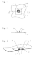
- the device chosen as an embodiment consists essentially of a mandrel piece 1, which is connected to a first workpiece 2 and a sleeve piece 3, which is connected to a second workpiece 4.
- the first workpiece 2 is in the embodiment, a sheet metal body, in which the mandrel piece 1 is formed directly.
- the mandrel piece 1 is formed as a one-piece cup-shaped Blechumformteil with a double wall 11,12 and closed bottom 13.
- the sleeve piece 3 is formed in the embodiment as Blechumformteil. It consists essentially of an annular body 31, in which a spring washer 32 is formed.
- the spring washer 32 has inwardly encircling spring elements 33, which are employed in the assembled state of the sleeve piece 3 obliquely to the outer wall 11 of the mandrel piece 1.
- the mandrel piece 1 is tapered in the direction of the first workpiece 2, so that at its open end there is an enlargement of diameter, against which the spring elements 33 are tilted in the mounted state of the sleeve piece 3.
- the second workpiece 4 having a bore 41 is placed on the first workpiece 2, so that the mandrel piece 1 passes through the bore 41.
- the spring elements 33 of the annular body 31 of the sleeve piece 3 are first spread apart and then follow the outer contour of the mandrel piece 1, against which they lie obliquely employed. As a result, a non-positive and positive connection between sleeve piece 3 and mandrel 1 is effected.
- the spring elements 33 When applying a tensile force on the second workpiece 4, the spring elements 33 tilt against the mandrel piece 1, whereby a release of the compound is prevented up to a limit force. When the limit force is exceeded, the spring elements 33 are irreversibly deformed, so that a once dissolved connection is recognizable without wieteres.
- the sleeve piece is firmly connected to the second workpiece 4.
- the sleeve piece 3 can be subsequently applied after positioning of the second workpiece 4 for fixing the second workpiece 4 on the mandrel piece 1.
- FIG. 4 The production of the mandrel piece 1 is shown schematically in FIG FIG. 4 shown.
- a cup 10 is first formed in the first workpiece 2, the bottom 13 is formed in the manner of a spherical cap.
- the formation of the cup takes place by deep drawing.
- the bottom 13 of the cup 10 in the opposite direction to the punch effective direction of the preceding Pulled over a punch 5 in the direction of the sheet metal part 2.
- the outer contour of the cup 10 is guided over a mold 6.
- the cup has a height of 10 mm with an inner diameter of 6 mm.
- the sheet 2 has a thickness of 0.5 mm.
- the mandrel piece 1 thus produced has a height of about 5 mm.
- the stamp 5 used for inserting the bottom 13 is cylindrical in shape and, in the exemplary embodiment, has an external diameter of 3.9 mm.
- the device according to the invention is simple and inexpensive to produce by the one-piece design of the mandrel piece, which can be manufactured by a single combined forming process. Through the bottom 13, the mandrel piece 1 is closed to the outside, so that even tamper-resistant connections, such as those required for seals of containers, can be realized.
Landscapes
- Engineering & Computer Science (AREA)
- General Engineering & Computer Science (AREA)
- Mechanical Engineering (AREA)
- Closures For Containers (AREA)
Priority Applications (1)
| Application Number | Priority Date | Filing Date | Title |
|---|---|---|---|
| EP10005615A EP2389825A1 (fr) | 2010-05-28 | 2010-05-28 | Dispositif de connexion |
Applications Claiming Priority (1)
| Application Number | Priority Date | Filing Date | Title |
|---|---|---|---|
| EP10005615A EP2389825A1 (fr) | 2010-05-28 | 2010-05-28 | Dispositif de connexion |
Publications (1)
| Publication Number | Publication Date |
|---|---|
| EP2389825A1 true EP2389825A1 (fr) | 2011-11-30 |
Family
ID=42782073
Family Applications (1)
| Application Number | Title | Priority Date | Filing Date |
|---|---|---|---|
| EP10005615A Withdrawn EP2389825A1 (fr) | 2010-05-28 | 2010-05-28 | Dispositif de connexion |
Country Status (1)
| Country | Link |
|---|---|
| EP (1) | EP2389825A1 (fr) |
Citations (3)
| Publication number | Priority date | Publication date | Assignee | Title |
|---|---|---|---|---|
| DE2014039A1 (en) * | 1970-03-24 | 1971-10-07 | Radtke, Kurt, 3500 Kassel | Hollow closure bolts |
| WO1997015207A1 (fr) * | 1995-10-20 | 1997-05-01 | Cobra S.R.L. | Bouton-pression |
| DE202007001877U1 (de) * | 2007-02-05 | 2007-04-05 | Berning + Söhne GmbH & Co. KG | Druckknopf zum Verschließen von Bekleidungsstücken, Taschen o.dgl. |
-
2010
- 2010-05-28 EP EP10005615A patent/EP2389825A1/fr not_active Withdrawn
Patent Citations (3)
| Publication number | Priority date | Publication date | Assignee | Title |
|---|---|---|---|---|
| DE2014039A1 (en) * | 1970-03-24 | 1971-10-07 | Radtke, Kurt, 3500 Kassel | Hollow closure bolts |
| WO1997015207A1 (fr) * | 1995-10-20 | 1997-05-01 | Cobra S.R.L. | Bouton-pression |
| DE202007001877U1 (de) * | 2007-02-05 | 2007-04-05 | Berning + Söhne GmbH & Co. KG | Druckknopf zum Verschließen von Bekleidungsstücken, Taschen o.dgl. |
Similar Documents
| Publication | Publication Date | Title |
|---|---|---|
| DE102012221698B3 (de) | Verbindungseinrichtung sowie Verfahren zur Herstellung einer Verbindungseinrichtung | |
| EP1960731A1 (fr) | Unite d'actionnement pyrotechnique, son procede de production, et module de poche a gaz pourvu d'une unite d'actionnement de ce type | |
| DE102008013895A1 (de) | Diebstahlgesichertes Schraubteil | |
| EP2220510B1 (fr) | Procédé de fabrication d'un capteur de champ magnétique et capteur fabriqué selon ledit procédé | |
| DE102016206864A1 (de) | Kugelgelenk, insbesondere für ein Fahrwerk eines Kraftfahrzeugs, sowie Verfahren zur Montage eines solchen Kugelgelenks | |
| EP1513721B1 (fr) | Bouchon d'obturation | |
| DE102015010477A1 (de) | Getränkedose aus Kunststoff | |
| DE102017219410A1 (de) | Bauteilverbund und Steuergerät | |
| DE102013007036A1 (de) | Kontaktiereinrichtung für eine elektrische Kontaktanordnung sowie Verfahren zu deren Herstellung | |
| DE202022101193U1 (de) | Kupplungsbolzen einer Steckkupplung, erstes Bauteil mit dem Kupplungsbolzen, dazugehörige Steckkupplung und Verbindungsstruktur zweier Bauteile | |
| EP3370989B1 (fr) | Réservoir muni d'un dispositif de renforcement | |
| EP1446587B1 (fr) | Articulation | |
| EP2389825A1 (fr) | Dispositif de connexion | |
| DE19949161B4 (de) | Befestigungsanordnung zum Befestigen eines Nietelementes an einem plattenförmigen Bauteil | |
| DE102015117100B3 (de) | Sicherung für Bügelverschlussflaschen | |
| DE60117949T2 (de) | Eingepresste Ventildichtung und Herstellungsverfahren für dieselbe | |
| DE202010007351U1 (de) | Verbindungsvorrichtung | |
| EP3947992B1 (fr) | Joint à rotule pour châssis de véhicule et procédé de fabrication dudit joint à rotule | |
| DE102014212701A1 (de) | Vorrichtung zur Betätigung einer Kupplung in einem hydraulischen System und Verfahren zur Herstellung einer solchen Vorrichtung | |
| EP3490828B1 (fr) | Élément de rupture pour support de module, réalisé sous la forme d'une séparation espace humide/espace sec, d'une porte ou d'un ouvrant d'un véhicule automobile | |
| DE102012222203B4 (de) | Batteriezelle mit verbessertem Verschluss einer Befüllungsöffnung | |
| DE102016104396A1 (de) | Elektrisches Massesystem und Masseverbindungs-Herstellungsverfahren | |
| EP4431415B1 (fr) | Ensemble comprenant un récipient extérieur avec un récipient intérieur disposé dans celui-ci et procédé d'ouverture et de fabrication d'un ensemble | |
| EP1422429B1 (fr) | Articulation à rotule | |
| AT523947B1 (de) | Vorrichtung zur Zudosierung eines Dosiermittels für eine in einer Flasche abgefüllte Flüssigkeit |
Legal Events
| Date | Code | Title | Description |
|---|---|---|---|
| AK | Designated contracting states |
Kind code of ref document: A1 Designated state(s): AL AT BE BG CH CY CZ DE DK EE ES FI FR GB GR HR HU IE IS IT LI LT LU LV MC MK MT NL NO PL PT RO SE SI SK SM TR |
|
| AX | Request for extension of the european patent |
Extension state: BA ME RS |
|
| PUAI | Public reference made under article 153(3) epc to a published international application that has entered the european phase |
Free format text: ORIGINAL CODE: 0009012 |
|
| 17P | Request for examination filed |
Effective date: 20120510 |
|
| 17Q | First examination report despatched |
Effective date: 20121031 |
|
| RIC1 | Information provided on ipc code assigned before grant |
Ipc: A44B 17/00 20060101AFI20130909BHEP Ipc: B21D 39/03 20060101ALI20130909BHEP Ipc: F16B 21/07 20060101ALI20130909BHEP Ipc: F16B 5/06 20060101ALI20130909BHEP Ipc: B21D 22/24 20060101ALI20130909BHEP |
|
| RAP1 | Party data changed (applicant data changed or rights of an application transferred) |
Owner name: BEDNORZ GMBH & CO. KG |
|
| STAA | Information on the status of an ep patent application or granted ep patent |
Free format text: STATUS: THE APPLICATION IS DEEMED TO BE WITHDRAWN |
|
| 18D | Application deemed to be withdrawn |
Effective date: 20131202 |