EP2390136A1 - Ensemble doté d'un boîtier comportant une carte de circuit supportant plusieurs diodes électroluminescentes - Google Patents
Ensemble doté d'un boîtier comportant une carte de circuit supportant plusieurs diodes électroluminescentes Download PDFInfo
- Publication number
- EP2390136A1 EP2390136A1 EP10164507A EP10164507A EP2390136A1 EP 2390136 A1 EP2390136 A1 EP 2390136A1 EP 10164507 A EP10164507 A EP 10164507A EP 10164507 A EP10164507 A EP 10164507A EP 2390136 A1 EP2390136 A1 EP 2390136A1
- Authority
- EP
- European Patent Office
- Prior art keywords
- light
- led
- light emitting
- optical element
- emitting diode
- Prior art date
- Legal status (The legal status is an assumption and is not a legal conclusion. Google has not performed a legal analysis and makes no representation as to the accuracy of the status listed.)
- Withdrawn
Links
- 230000003287 optical effect Effects 0.000 claims abstract description 81
- 230000011664 signaling Effects 0.000 claims abstract description 17
- 238000004519 manufacturing process Methods 0.000 description 4
- 239000003086 colorant Substances 0.000 description 2
- 238000005286 illumination Methods 0.000 description 2
- 239000000463 material Substances 0.000 description 2
- 208000016261 weight loss Diseases 0.000 description 2
- 230000000712 assembly Effects 0.000 description 1
- 238000000429 assembly Methods 0.000 description 1
- 230000005855 radiation Effects 0.000 description 1
- 230000003595 spectral effect Effects 0.000 description 1
- 238000005728 strengthening Methods 0.000 description 1
- 239000012780 transparent material Substances 0.000 description 1
- 239000013585 weight reducing agent Substances 0.000 description 1
Images


Classifications
-
- B—PERFORMING OPERATIONS; TRANSPORTING
- B60—VEHICLES IN GENERAL
- B60Q—ARRANGEMENT OF SIGNALLING OR LIGHTING DEVICES, THE MOUNTING OR SUPPORTING THEREOF OR CIRCUITS THEREFOR, FOR VEHICLES IN GENERAL
- B60Q1/00—Arrangement of optical signalling or lighting devices, the mounting or supporting thereof or circuits therefor
- B60Q1/26—Arrangement of optical signalling or lighting devices, the mounting or supporting thereof or circuits therefor the devices being primarily intended to indicate the vehicle, or parts thereof, or to give signals, to other traffic
- B60Q1/2661—Arrangement of optical signalling or lighting devices, the mounting or supporting thereof or circuits therefor the devices being primarily intended to indicate the vehicle, or parts thereof, or to give signals, to other traffic mounted on parts having other functions
- B60Q1/2665—Arrangement of optical signalling or lighting devices, the mounting or supporting thereof or circuits therefor the devices being primarily intended to indicate the vehicle, or parts thereof, or to give signals, to other traffic mounted on parts having other functions on rear-view mirrors
-
- B—PERFORMING OPERATIONS; TRANSPORTING
- B60—VEHICLES IN GENERAL
- B60Q—ARRANGEMENT OF SIGNALLING OR LIGHTING DEVICES, THE MOUNTING OR SUPPORTING THEREOF OR CIRCUITS THEREFOR, FOR VEHICLES IN GENERAL
- B60Q1/00—Arrangement of optical signalling or lighting devices, the mounting or supporting thereof or circuits therefor
- B60Q1/26—Arrangement of optical signalling or lighting devices, the mounting or supporting thereof or circuits therefor the devices being primarily intended to indicate the vehicle, or parts thereof, or to give signals, to other traffic
- B60Q1/2607—Arrangement of optical signalling or lighting devices, the mounting or supporting thereof or circuits therefor the devices being primarily intended to indicate the vehicle, or parts thereof, or to give signals, to other traffic comprising at least two indicating lamps
-
- B—PERFORMING OPERATIONS; TRANSPORTING
- B60—VEHICLES IN GENERAL
- B60Q—ARRANGEMENT OF SIGNALLING OR LIGHTING DEVICES, THE MOUNTING OR SUPPORTING THEREOF OR CIRCUITS THEREFOR, FOR VEHICLES IN GENERAL
- B60Q1/00—Arrangement of optical signalling or lighting devices, the mounting or supporting thereof or circuits therefor
- B60Q1/26—Arrangement of optical signalling or lighting devices, the mounting or supporting thereof or circuits therefor the devices being primarily intended to indicate the vehicle, or parts thereof, or to give signals, to other traffic
- B60Q1/34—Arrangement of optical signalling or lighting devices, the mounting or supporting thereof or circuits therefor the devices being primarily intended to indicate the vehicle, or parts thereof, or to give signals, to other traffic for indicating change of drive direction
-
- F—MECHANICAL ENGINEERING; LIGHTING; HEATING; WEAPONS; BLASTING
- F21—LIGHTING
- F21S—NON-PORTABLE LIGHTING DEVICES; SYSTEMS THEREOF; VEHICLE LIGHTING DEVICES SPECIALLY ADAPTED FOR VEHICLE EXTERIORS
- F21S43/00—Signalling devices specially adapted for vehicle exteriors, e.g. brake lamps, direction indicator lights or reversing lights
- F21S43/10—Signalling devices specially adapted for vehicle exteriors, e.g. brake lamps, direction indicator lights or reversing lights characterised by the light source
- F21S43/13—Signalling devices specially adapted for vehicle exteriors, e.g. brake lamps, direction indicator lights or reversing lights characterised by the light source characterised by the type of light source
- F21S43/14—Light emitting diodes [LED]
-
- F—MECHANICAL ENGINEERING; LIGHTING; HEATING; WEAPONS; BLASTING
- F21—LIGHTING
- F21S—NON-PORTABLE LIGHTING DEVICES; SYSTEMS THEREOF; VEHICLE LIGHTING DEVICES SPECIALLY ADAPTED FOR VEHICLE EXTERIORS
- F21S43/00—Signalling devices specially adapted for vehicle exteriors, e.g. brake lamps, direction indicator lights or reversing lights
- F21S43/20—Signalling devices specially adapted for vehicle exteriors, e.g. brake lamps, direction indicator lights or reversing lights characterised by refractors, transparent cover plates, light guides or filters
- F21S43/235—Light guides
-
- F—MECHANICAL ENGINEERING; LIGHTING; HEATING; WEAPONS; BLASTING
- F21—LIGHTING
- F21Y—INDEXING SCHEME ASSOCIATED WITH SUBCLASSES F21K, F21L, F21S and F21V, RELATING TO THE FORM OR THE KIND OF THE LIGHT SOURCES OR OF THE COLOUR OF THE LIGHT EMITTED
- F21Y2115/00—Light-generating elements of semiconductor light sources
- F21Y2115/10—Light-emitting diodes [LED]
Definitions
- the present application relates to external rear-view mirrors having signalling modules using light emitting diodes.
- Light emitting diodes are increasingly being used in vehicles. Light emitting sources consume less energy compared to traditional incandescent light sources and have an improved lifespan. LEDs can serve for signalling functions.
- DRL Day Running Lamp
- Vehicle lights especially when arranged within external rear-view mirrors, can only make use of limited space.
- rear-view mirror have highly curved external surfaces that do not allow simple arrangements of light sources.
- Document US20050270791 discloses a vehicle light system comprising several light sources, typically light emitting diodes, positioned on different planes. Said planes are disposed in a staggered fashion defining step portions. The overall surfaces of said portions has to accommodate the shape and size of external surfaces of a car.
- the object of the present invention is to provide a lighting system on a rear-view mirror surmounting space limitation and highly curved external surfaces and geometries and yet capable of providing an efficient signalling system for the vehicle.
- a further object of the invention is to provide an optical system for rear-view mirrors that has a light weight and can spare on the amount of materials needed for the optical components.
- the present invention solves at least one of the problems mentioned above by providing optical elements with geometries, especially branched surfaces, that allow an optimal use of scarce space in external rear-view modules.
- an assembly having a housing comprising a circuit board supporting a plurality of light emitting diodes, characterised by at least one optical element with a first light input surface optically connected to a first light emitting diode, with a second light input surface optically connected to a second light emitting diode, wherein said optical element is configured for directing light coming for said first and second light emitting diodes onto a common light output surface, whereby both light emitting diodes have a signalling function.
- the first light emitting diode is configured to have a vehicle day running light function and/or the second light emitting diode is configured to have a blinker function.
- the common light output surface is parallel to an external surface of said housing and wherein said optical element is configured for directing light coming from said first light emitting diode onto a predetermined direction, preferably the driving direction of the vehicle.
- the invention also refers to an assembly for a vehicle having a housing comprising a circuit board supporting a plurality of light emitting diodes, characterised by at least one optical element with a first light input surface optically connected to a first light emitting diode and a light output surface, wherein said optical element is configured for directing light coming for said first light input surface onto said light output surface and to direct light coming from said first light emitting diode onto a predetermined direction and wherein said light output surface is parallel to an external surface of said rear-mirror view housing, and wherein preferably the optical element is configured to define two or more light output branches impinging on said light output surface at different spots.
- the invention further refers to an assembly for a vehicle comprising a housing and at least a circuit board supporting a plurality of light emitting diodes, characterised in that said circuit board is flat and in that it comprises at least one optical element for directing light coming for said light emitting diodes onto a predetermined direction, and which can include the following optional features:
- the circuit board can be arranged in a single plane or in a series of supporting steps.
- the leds are placed every other step, said steps supporting leds being destined to be placed perpendicular to the longitudinal direction of the vehicle when said assembly is mounted on the vehicle.
- the invention refers also to an external rear-view mirror for a vehicle comprising any assembly of the invention previously described.
- the invention provides for an assembly for rear view mirrors that proposes an efficient use of space and which is also capable of simultaneously accommodating a plurality of signalling functions without prejudice to achieving a compact arrangement.
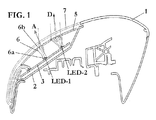
- Embodiments shown in Figure 1 show a flat circuit board 3 comprising a number of light emitting diodes LED-1, LED-2. Said light emitting diodes may emit any desired colour or a combination of colours. Choice of colours may include amber if a blinker function is desired or white light if front vehicle illumination is desired. The spectral behaviour of each individual light emitting diode can be tailor made to a specific function and its output light strength and optical aperture chosen to meet specific needs in rear-view mirror applications.
- a flat circuit board 3 is particularly advantageous as it provides a simple module that can be fitted to a number of different rear-view mirror designs. As mentioned before, manufacturing of said circuit boards 3 is simple. Additionally flat geometries allow the manufacture of simple modular lighting modules, especially of mounting component on the circuit board 3.
- a light emitting module comprises a base 2 which is fitted, fixed or attached to the rear-view mirror and an external cover 7.
- Said external cover 7 preferably makes part of the external surface of said rear-view mirror housing 1.
- Said external cover 7 is normally made of transparent material.
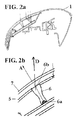
- Figure 2b show a detailed part of an optical element 6.
- the optical element is typically a non dispersive prism for guiding and changing the direction of light travel.
- the optical element 6 preferably uses total internal reflection to minimize light loses.
- Light emitting diodes LED1,LED-2 have a preferred emitting direction A. Radiation can be directed or scattered to any direction, but light emitting diodes are preferably configured so as to send the bulk of light in a predetermined emitting direction A. This direction A is advantageously perpendicular to the circuit board 3 main surface.
- the optical element 6 can show several degrees of symmetry. As can be shown in Figures 2a and 2b , a rotational symmetry around an axis parallel to the emitting direction A can be shown. If the optical element shows a number of branches, individual symmetries of each branch are possible.
- the light output surface 6b of the optical element 6 is built as Fresnel lens which redirects or collimates light from emitting direction A onto a predetermined direction D efficiently.
- the optical element is typically a non dispersive prism for guiding and changing the direction of light travel.
- the optical element 6 preferably uses total internal reflection to minimize light loses. Waveguides may also be used instead.
- a preferred embodiment in the present invention is to maximize light output surface by making surfaces of optical elements 6 parallel to the external surfaces of the rear-view mirror modules.
- the optical element 6 comprises a first light input surface 6a in optical connection with a first light emitting diode LED-1.
- a particularly simple optical performance is achieved if said first light input surface 6a faces said first light emitting diode LED-1. Optical losses can thus be minimized and with increased light output and a better thermal behaviour.
- the optical element 6 is preferably in contact with the light output surface 6b.
- the light output surface 6b is preferably parallel to an external surface of the rear-view mirror housing 1.
- the output surface of light allows for more light power and for a surface compatible with the overall dimension of the rear-view mirror.
- External rear-view mirrors are particularly prone to damage. These external units have to stick out from the car main body being exposed to increased tear and wear, changing climate conditions and vandalism.
- the optical elements 6 bridging the distance between the circuit board 3 and an cover 5 will provide a stable mechanical system with an increased number of joints between the circuit board 3 and the cover 5.
- the overall system will be more rugged and less prone to structural or mechanical damage.
- a rear-view mirror is obtained that is rugged and can withstand the wear and tear of driving conditions.
- Figures 3a and 3b shows another embodiment of the present invention.
- the light output surface shows a plurality of legs or branches 6b which impinge on selected through holes on a cover 5 surface. With said arrangement, a number of light beams can be selected without increasing the number of optical elements 6 and light emitting diodes LED-1,LED-2 present in the system.
- said cover 5 can be made redundant by making said legs of branches of optical the element 6 impinge or contact the external cover 7 directly.
- German publication DE 102007013082 D2 of prior art search discloses a signal light for a brake light. It describes two elongated legs or branches that decouples light in two different directions.
- An embodiment of the present invention describes an optical element 6 with a first light input surface defining a first leg or branch and a second light input surface 6c defining a second leg or branch, wherein said first and second legs or branches are arranged so as to achieve a light weight optical element 6.
- the optical element 6 with light input optical surfaces disposed as legs or branches allows the manufacture of light optical elements. Material bridging legs is made redundant as no reflected of scattered light will enter that area.
- the present invention provides and embodiment wherein a system can simultaneously accommodate two signalling functions and yet be compact.
- the optical element 6 includes a first light input surface 6a optically connected to one first light emitting diode LED-1. It also includes a second light input surface 6c optically connected to a second light emitting diode LED-2, wherein said optical element 6 is configured for directing light coming for said first and second light emitting diodes LED-1, LED-2 onto a common light output surface 6b, whereby said first light emitting diode LED-1 and said second light emitting diode LED-2 have a signalling function, typically a DRL function and a blinker function.
- a signalling function typically a DRL function and a blinker function.
- Figure 4b shows details of an optical element that constitutes a waveguide 9 redirecting light to a rear point direction C. This arrangement allows lights, specially signalling lights and blinkers, to be seen from rear and side positions.
- optical element 6 designs can reveal themselves are incapable of offering sufficiently large light reflection.
- the outer surface of the optical element 6 is preferably mirrored. Light which would escape the optical element 6 is redirected or piped back inside the optical medium of the optical element.
- Figure 5 shows two waveguides 9,10 for redirecting light in opposing directions. Other light sources, the light emitting diodes are not shown in this particular figure 5 .
- Directing light in opposite direction makes visibility and signalling of vehicle operations an easier task.
Landscapes
- Engineering & Computer Science (AREA)
- Mechanical Engineering (AREA)
- General Engineering & Computer Science (AREA)
- Physics & Mathematics (AREA)
- Microelectronics & Electronic Packaging (AREA)
- Optics & Photonics (AREA)
- Non-Portable Lighting Devices Or Systems Thereof (AREA)
- Lighting Device Outwards From Vehicle And Optical Signal (AREA)
- Led Device Packages (AREA)
Priority Applications (5)
| Application Number | Priority Date | Filing Date | Title |
|---|---|---|---|
| EP10164507A EP2390136A1 (fr) | 2010-05-31 | 2010-05-31 | Ensemble doté d'un boîtier comportant une carte de circuit supportant plusieurs diodes électroluminescentes |
| DE112011101860.6T DE112011101860B4 (de) | 2010-05-31 | 2011-05-31 | Außenspiegel-Anordnung mit einem Gehäuse umfassend eine Schaltkreisplatine mit einer Mehrzahl an lichtemittierenden Dioden |
| CN201180026705.5A CN102947131B (zh) | 2010-05-31 | 2011-05-31 | 具有壳体包括支撑多个发光二极管的电路板的外部后视镜组件 |
| PCT/EP2011/058997 WO2011151352A1 (fr) | 2010-05-31 | 2011-05-31 | Ensemble rétroviseur extérieur comportant un logement comprenant une carte de circuit imprimé supportant une pluralité de diodes électroluminescentes |
| US13/697,903 US8882315B2 (en) | 2010-05-31 | 2011-05-31 | External rear-view mirror assembly having a housing comprising a circuit board supporting a plurality of light emitting diodes |
Applications Claiming Priority (1)
| Application Number | Priority Date | Filing Date | Title |
|---|---|---|---|
| EP10164507A EP2390136A1 (fr) | 2010-05-31 | 2010-05-31 | Ensemble doté d'un boîtier comportant une carte de circuit supportant plusieurs diodes électroluminescentes |
Publications (1)
| Publication Number | Publication Date |
|---|---|
| EP2390136A1 true EP2390136A1 (fr) | 2011-11-30 |
Family
ID=42667028
Family Applications (1)
| Application Number | Title | Priority Date | Filing Date |
|---|---|---|---|
| EP10164507A Withdrawn EP2390136A1 (fr) | 2010-05-31 | 2010-05-31 | Ensemble doté d'un boîtier comportant une carte de circuit supportant plusieurs diodes électroluminescentes |
Country Status (5)
| Country | Link |
|---|---|
| US (1) | US8882315B2 (fr) |
| EP (1) | EP2390136A1 (fr) |
| CN (1) | CN102947131B (fr) |
| DE (1) | DE112011101860B4 (fr) |
| WO (1) | WO2011151352A1 (fr) |
Cited By (1)
| Publication number | Priority date | Publication date | Assignee | Title |
|---|---|---|---|---|
| ES2458428A1 (es) * | 2012-10-31 | 2014-05-05 | Fico Mirrors, S.A. | Conjunto retrovisor exterior de vehículo |
Families Citing this family (8)
| Publication number | Priority date | Publication date | Assignee | Title |
|---|---|---|---|---|
| DE102012025886B3 (de) | 2012-12-11 | 2022-05-25 | HELLA GmbH & Co. KGaA | Rangierleuchte für einen Seitenspiegel eines Fahrzeugs mit einem Reflektor und einer Streuplatte mit Prismenelementen |
| DE102012112066B4 (de) * | 2012-12-11 | 2022-04-28 | HELLA GmbH & Co. KGaA | Rangierleuchte für einen Seitenspiegel eines Fahrzeugs mit einem Lichtleitkörper |
| DE202015105115U1 (de) * | 2015-09-28 | 2016-12-30 | SMR Patents S.à.r.l. | Leuchteinheit und Rückblickspiegel für Fahrzeuge |
| US20170114978A1 (en) * | 2015-10-23 | 2017-04-27 | Kumar Singarajan | Assembly having an illuminable clear display surface coupled to a remote light source by a hidden optical waveguide |
| US10780819B2 (en) * | 2018-12-19 | 2020-09-22 | Ficosa North America Corporation | Vehicle winglet with sequential blinker |
| WO2021116922A1 (fr) | 2019-12-10 | 2021-06-17 | 3M Innovative Properties Company | Purificateur d'air ambiant électrique à indicateur visuel de qualité d'air |
| KR102914807B1 (ko) * | 2020-09-15 | 2026-01-19 | 현대모비스 주식회사 | 자동차용 램프 및 그 램프를 포함하는 자동차 |
| CN115447489B (zh) * | 2022-08-31 | 2026-01-09 | 蔚来汽车科技(安徽)有限公司 | 后视镜和具有其的车辆 |
Citations (9)
| Publication number | Priority date | Publication date | Assignee | Title |
|---|---|---|---|---|
| EP0947761A1 (fr) | 1998-03-31 | 1999-10-06 | Valeo Vision | Feu de signalisation comprenant plusieurs sources lumineuses |
| US20050052864A1 (en) * | 2003-09-09 | 2005-03-10 | Colip Matthew S. | Light emitting diode carrier |
| US20050270791A1 (en) | 2004-06-03 | 2005-12-08 | Jihn-Shiun Lee | Vehicle light for producing light whose form depends on orientations of plural refraction sides |
| EP1746339A1 (fr) * | 2005-07-21 | 2007-01-24 | Valeo Vision | Dispositif d'éclairage ou de signalisation, notamment pour véhicule automobile |
| EP1750054A1 (fr) * | 2005-08-01 | 2007-02-07 | Volkswagen Aktiengesellschaft | Dispositif d'éclairage pour un véhicule |
| EP1854667A1 (fr) * | 2006-05-11 | 2007-11-14 | Schefenacker Patents S.à.r.l. | Dispositif d'éclairage et rétroviseur extérieur avec un dispositif d'éclairage |
| DE102007013082A1 (de) | 2007-03-14 | 2008-09-18 | Hella Kgaa Hueck & Co. | Signalleuchte |
| EP2012056A1 (fr) * | 2007-07-02 | 2009-01-07 | Valeo Vision | Dispositif lumineux de signalisation pour véhicule automobile |
| EP2161494A1 (fr) * | 2008-09-05 | 2010-03-10 | Hella KG Hueck & Co. | Dispositif d'éclairage pour un véhicule automobile |
Family Cites Families (6)
| Publication number | Priority date | Publication date | Assignee | Title |
|---|---|---|---|---|
| US6637917B2 (en) * | 2000-10-04 | 2003-10-28 | Fer Fahrzeugelektrik Gmbh | Side flashing lamp |
| ES2247920B1 (es) | 2004-04-05 | 2007-05-01 | Fico Mirrors, S.A. | Conjunto de iluminacion con funciones de seguridad y señalizacion para vehiculos automoviles. |
| JP4276250B2 (ja) * | 2006-10-11 | 2009-06-10 | 株式会社ミツバ | ターンランプ付きドアミラー |
| JP5603571B2 (ja) * | 2009-06-05 | 2014-10-08 | 株式会社小糸製作所 | 車両用灯具 |
| JP5469965B2 (ja) * | 2009-09-04 | 2014-04-16 | 株式会社小糸製作所 | サイドターンシグナルランプ |
| EP2325046B1 (fr) * | 2009-11-17 | 2016-03-02 | SMR Patents S.à.r.l. | Procédé d'assemblage d'un module d'indicateur de signal de changement de direction et sous-module d'indicateur de signal de changement de direction |
-
2010
- 2010-05-31 EP EP10164507A patent/EP2390136A1/fr not_active Withdrawn
-
2011
- 2011-05-31 CN CN201180026705.5A patent/CN102947131B/zh active Active
- 2011-05-31 WO PCT/EP2011/058997 patent/WO2011151352A1/fr not_active Ceased
- 2011-05-31 US US13/697,903 patent/US8882315B2/en active Active
- 2011-05-31 DE DE112011101860.6T patent/DE112011101860B4/de active Active
Patent Citations (9)
| Publication number | Priority date | Publication date | Assignee | Title |
|---|---|---|---|---|
| EP0947761A1 (fr) | 1998-03-31 | 1999-10-06 | Valeo Vision | Feu de signalisation comprenant plusieurs sources lumineuses |
| US20050052864A1 (en) * | 2003-09-09 | 2005-03-10 | Colip Matthew S. | Light emitting diode carrier |
| US20050270791A1 (en) | 2004-06-03 | 2005-12-08 | Jihn-Shiun Lee | Vehicle light for producing light whose form depends on orientations of plural refraction sides |
| EP1746339A1 (fr) * | 2005-07-21 | 2007-01-24 | Valeo Vision | Dispositif d'éclairage ou de signalisation, notamment pour véhicule automobile |
| EP1750054A1 (fr) * | 2005-08-01 | 2007-02-07 | Volkswagen Aktiengesellschaft | Dispositif d'éclairage pour un véhicule |
| EP1854667A1 (fr) * | 2006-05-11 | 2007-11-14 | Schefenacker Patents S.à.r.l. | Dispositif d'éclairage et rétroviseur extérieur avec un dispositif d'éclairage |
| DE102007013082A1 (de) | 2007-03-14 | 2008-09-18 | Hella Kgaa Hueck & Co. | Signalleuchte |
| EP2012056A1 (fr) * | 2007-07-02 | 2009-01-07 | Valeo Vision | Dispositif lumineux de signalisation pour véhicule automobile |
| EP2161494A1 (fr) * | 2008-09-05 | 2010-03-10 | Hella KG Hueck & Co. | Dispositif d'éclairage pour un véhicule automobile |
Cited By (1)
| Publication number | Priority date | Publication date | Assignee | Title |
|---|---|---|---|---|
| ES2458428A1 (es) * | 2012-10-31 | 2014-05-05 | Fico Mirrors, S.A. | Conjunto retrovisor exterior de vehículo |
Also Published As
| Publication number | Publication date |
|---|---|
| WO2011151352A1 (fr) | 2011-12-08 |
| DE112011101860T5 (de) | 2013-06-06 |
| CN102947131A (zh) | 2013-02-27 |
| US8882315B2 (en) | 2014-11-11 |
| US20130083552A1 (en) | 2013-04-04 |
| CN102947131B (zh) | 2015-07-22 |
| DE112011101860B4 (de) | 2020-12-17 |
Similar Documents
| Publication | Publication Date | Title |
|---|---|---|
| US8882315B2 (en) | External rear-view mirror assembly having a housing comprising a circuit board supporting a plurality of light emitting diodes | |
| KR101268814B1 (ko) | 차량 미러 조립체용 방향 지시등 모듈 및 방향 지시등 모듈을 포함하는 차량 미러 조립체 | |
| EP1022510B1 (fr) | Système de feu arrière à fonctions multiples avec une optique unitaire pour automobiles | |
| EP2157363B1 (fr) | Element optique pour feu de véhicule automobile | |
| US9689550B2 (en) | Vehicular lamp device | |
| EP3418626B1 (fr) | Lampe et véhicule équipé de cette dernière | |
| US11320112B2 (en) | Optical device for an automobile vehicle | |
| US11754250B2 (en) | Vehicle lamp | |
| US20100195342A1 (en) | Automotive Signal Light Employing Multi-focal Length Light Pipes | |
| US7070311B2 (en) | Vehicle light for producing light whose form depends on orientations of plural refraction elements | |
| KR20090123826A (ko) | 자동차 후방 콤비네이션 램프의 후방 적재된 led 모듈 | |
| US20060285348A1 (en) | Vehicular light assembly | |
| US9452707B1 (en) | Vehicle light apparatus | |
| EP3228924B1 (fr) | Lampe de véhicule | |
| CN114787557A (zh) | 车辆用灯 | |
| EP3572724A1 (fr) | Outil d'éclairage pour véhicule | |
| EP3929034B1 (fr) | Lampe de véhicule avec un guide de lumière | |
| US20080278961A1 (en) | Hybrid Optics for L.E.D. Lamp | |
| US10344939B2 (en) | Vehicle lighting assembly | |
| CN107435882A (zh) | 照明装置 | |
| US7703960B2 (en) | Light for motor vehicles | |
| CN111412426A (zh) | 一种车灯光学元件、车灯模组、车辆前照灯和车辆 | |
| CN110836355B (zh) | 用于交通工具的照明系统 | |
| KR20040099308A (ko) | 발광 유닛, 특히 자동차의 외부 후사경에 있는 보조램프로서의 발광 유닛 | |
| JP2021097013A (ja) | 車両用灯具 |
Legal Events
| Date | Code | Title | Description |
|---|---|---|---|
| AK | Designated contracting states |
Kind code of ref document: A1 Designated state(s): AL AT BE BG CH CY CZ DE DK EE ES FI FR GB GR HR HU IE IS IT LI LT LU LV MC MK MT NL NO PL PT RO SE SI SK SM TR |
|
| AX | Request for extension of the european patent |
Extension state: BA ME RS |
|
| PUAI | Public reference made under article 153(3) epc to a published international application that has entered the european phase |
Free format text: ORIGINAL CODE: 0009012 |
|
| STAA | Information on the status of an ep patent application or granted ep patent |
Free format text: STATUS: THE APPLICATION IS DEEMED TO BE WITHDRAWN |
|
| 18D | Application deemed to be withdrawn |
Effective date: 20120531 |