EP2390146A1 - Dispositif de tension de sangle - Google Patents
Dispositif de tension de sangle Download PDFInfo
- Publication number
- EP2390146A1 EP2390146A1 EP11167624A EP11167624A EP2390146A1 EP 2390146 A1 EP2390146 A1 EP 2390146A1 EP 11167624 A EP11167624 A EP 11167624A EP 11167624 A EP11167624 A EP 11167624A EP 2390146 A1 EP2390146 A1 EP 2390146A1
- Authority
- EP
- European Patent Office
- Prior art keywords
- take
- spool
- housing chamber
- shaft
- webbing
- Prior art date
- Legal status (The legal status is an assumption and is not a legal conclusion. Google has not performed a legal analysis and makes no representation as to the accuracy of the status listed.)
- Granted
Links
- 230000035515 penetration Effects 0.000 claims description 12
- 230000000149 penetrating effect Effects 0.000 claims description 3
- 230000001105 regulatory effect Effects 0.000 abstract description 11
- 239000007787 solid Substances 0.000 description 2
- 230000006835 compression Effects 0.000 description 1
- 238000007906 compression Methods 0.000 description 1
- 238000004512 die casting Methods 0.000 description 1
- 230000002708 enhancing effect Effects 0.000 description 1
- 238000000465 moulding Methods 0.000 description 1
- 230000002093 peripheral effect Effects 0.000 description 1
Images



Classifications
-
- B—PERFORMING OPERATIONS; TRANSPORTING
- B60—VEHICLES IN GENERAL
- B60R—VEHICLES, VEHICLE FITTINGS, OR VEHICLE PARTS, NOT OTHERWISE PROVIDED FOR
- B60R22/00—Safety belts or body harnesses in vehicles
- B60R22/34—Belt retractors, e.g. reels
-
- B—PERFORMING OPERATIONS; TRANSPORTING
- B60—VEHICLES IN GENERAL
- B60R—VEHICLES, VEHICLE FITTINGS, OR VEHICLE PARTS, NOT OTHERWISE PROVIDED FOR
- B60R22/00—Safety belts or body harnesses in vehicles
- B60R22/34—Belt retractors, e.g. reels
- B60R22/36—Belt retractors, e.g. reels self-locking in an emergency
-
- B—PERFORMING OPERATIONS; TRANSPORTING
- B60—VEHICLES IN GENERAL
- B60R—VEHICLES, VEHICLE FITTINGS, OR VEHICLE PARTS, NOT OTHERWISE PROVIDED FOR
- B60R22/00—Safety belts or body harnesses in vehicles
- B60R22/34—Belt retractors, e.g. reels
- B60R22/36—Belt retractors, e.g. reels self-locking in an emergency
- B60R22/40—Belt retractors, e.g. reels self-locking in an emergency responsive only to vehicle movement
-
- B—PERFORMING OPERATIONS; TRANSPORTING
- B60—VEHICLES IN GENERAL
- B60R—VEHICLES, VEHICLE FITTINGS, OR VEHICLE PARTS, NOT OTHERWISE PROVIDED FOR
- B60R22/00—Safety belts or body harnesses in vehicles
- B60R22/34—Belt retractors, e.g. reels
- B60R2022/3419—Belt retractors, e.g. reels with end lock preventing means
Definitions
- the present invention relates to a webbing take-up device that takes up a webbing applied to a vehicle passenger.
- the spool is provided with a slit through which a proximal end portion of the webbing is made to pass. So, it is further necessary for the spool to have sufficient strength.
- the present invention has an object to provide a webbing take-up device capable of enhancing strength of a take-up shaft even though the take-up shaft is provided with a slit.
- a webbing take-up device of a first aspect of the resent invention includes: a take-up shaft that is provided with a slit through which a webbing to be applied to a vehicle passenger passes, the webbing being taken up on the take-up shaft by the take-up shaft being rotated in a take-up direction, and the take-up shaft being rotated in a drawing-out direction by the webbing being drawn out; a housing chamber that is provided integrally with an end portion of the take-up shaft in an axial direction of the take-up shaft, the housing chamber having an opening opened to an outer side in a radial direction of the take-up shaft, and having one side surface at a side of the take-up direction, an end portion of the one side surface at a side toward the opening begin arranged at a position which is away from a location where the slit is formed in a circumferential direction of the take-up shaft; and a lock member that is housed in the housing chamber, the lock member being engaged with the one side surface of the housing chamber
- the webbing take-up device is that, in the webbing take-up device according to the first aspect, the housing chamber further includes another side surface at a side toward the drawing-out direction, and the one side surface and the other side surface are away (become more distant) from each other as they go toward the outer side (approaching the outer side thereof) in the radial direction of the take-up shaft, and the one side surface and the other side surface are inclined with respect to a penetrating direction of the slit.
- the webbing to be applied to the vehicle passenger is made to pass through the slit provided in the take-up shaft.
- the take-up shaft is rotated in the take-up direction, thereby the webbing is taken up about the take-up shaft. Further, the webbing is drawn out from the take-up shaft, thereby the take-up shaft is rotated in the drawing-out direction.
- the housing chamber is provided integrally at the end portion in the axial direction of the take-up shaft, and the housing chamber is opened to the outer side in the radial direction of the take-up shaft.
- the lock member is housed in the housing chamber, and the one side surface at the take-up direction side of the housing chamber is engaged with the lock member in the predetermined occasion, and the rotation of the take-up shaft in the drawing-out direction is regulated.
- the end portion at the side of the opening (the opening-side end portion) of the one side surface of the housing chamber is arranged at such a position as to be away (separated) from the slit-formed location in the circumferential direction of the take-up shaft.
- a solid part (wall thickness part) which passes the one side surface of the housing chamber of the take-up shaft and is along the axial direction becomes larger, and hence strength of the take-up shaft can be enhanced.
- the webbing take-up device further includes a lock portion that is provided integrally with the end portion of the take-up shaft in the axial direction, and the housing chamber is formed in the lock portion such that an outer side in the axial direction of the housing chamber is closed by a wall portion at the outer side in the axial direction of the lock portion, and the housing chamber has the one side surface and another side surface at a side toward the drawing-out direction.
- the outer side of the housing chamber in the axial direction of the take-up shaft is closed.
- strength of the housing chamber can be enhanced, and the strength of the take-up shaft can be further enhanced.
- the lock member can be suppressed from being disengaged from the housing chamber to the outer side in the axial direction of the take-up shaft.
- the housing chamber further includes another side surface at a side toward the drawing-out direction, and the one side surface and the other side surface become more distant from each other approaching the outer side thereof in the radial direction of the take-up shaft, and the one side surface and the other side surface are inclined with respect to a penetrating direction of the slit.
- the take-up shaft is formed by molding, even if a part for forming the housing chamber is provided to the mold for forming shape of the take-up shaft, it is possible that the demolding directions of the mold are only two directions. As a result, a mold structure can be suppressed from being more complicated.
- the one side surface is formed to be parallel to a penetration direction of the slit.
- the other side surface is formed to be parallel to the penetration direction of the slit.
- the one side surface is formed to be inclined with respect to a penetration direction of the slit.
- a sliding surface which surface-abuts with and slides on the one side surface, is formed at the lock member, and the one side surface intersects with a side surface of the slit extending in the penetration direction of the slit at an intersecting portion when viewed in the axial direction.
- the one side surface is engaged with the sliding surface in a range which is from the end portion of the one side surface at the side toward the opening to the intersecting portion.
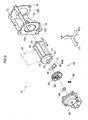
- Fig. 2 shows an overall structure of a webbing take-up device 10 according to an embodiment of the present invention by an exploded perspective view. Note that, in the figure, one side in a front and rear direction of a vehicle is indicated by an arrow LO, one side in a width direction of the vehicle is indicated by an arrow WO, and a vehicle upper side is indicated by an arrow UP.
- the webbing take-up device 10 includes a frame 12.
- the frame 12 is constituted by a substantially plate-like back plate 14 and a leg plate 16 and a leg plate 18 extending integrally and respectively from both ends in a width direction of the back plate 14.
- the back plate 14 is fixed to a vehicle body with fastening members (not shown in the drawings) such as bolts, thereby the webbing take-up device 10 is attached to the vehicle body.
- the leg plate 16 and the leg plate 18 are respectively provided with a circular arrangement hole 16A and a circular arrangement hole 18A formed therethrough.
- Ratchet teeth 16B (inner teeth) are formed on an outer periphery of the arrangement hole 16A.
- a spool 20 as a take-up shaft manufactured by die-casting or the like is rotatably arranged between the leg plate 16 and the leg plate 18.
- the spool 20 has a drum-like shape, and the spool 20 is provided with an elongated slit 26 penetrate-formed therethrough along a radial (diameter) direction.
- the slit 26 is constituted so that a longitudinal direction of the slit 26 is parallel to an axial direction of the spool 20.
- the webbing 30 Upon rotating the spool 20 in one direction about an axis thereof (it is arrow A direction in Fig. 2 , hereinafter, this direction is referred to as "take-up direction”), the webbing 30 is taken up from the proximal end side thereof around an outer peripheral portion of the spool 20 in a layered manner. Meanwhile, when the webbing 30 is pulled from a leading end side of the webbing 30, the webbing 30 is drawn out while the spool 20 is rotated in accordance therewith in another direction about the axis of the spool 20 (it is arrow B direction in Fig. 2 , hereinafter, this direction is referred to as "drawing-out direction").
- a substantially columnar-cylindrical support shaft 22 is provided integrally on a leg-plate 16 side of the spool 20.
- the support shaft 22 is projected to an outside of the leg plate 16 of the frame 12 through the arrangement hole 16A.
- a support shaft 24 which is in substantially rectangular column shape is provided integrally on a leg-plate 18 side of the spool 20.
- the support shaft 24 is arranged coaxially with the support shaft 22 and is projected to an outside of the leg plate 18 of the frame 12 through the arrangement hole 18A.
- a spiral spring (not shown in the drawings) as a take-up member is arranged on the outside of the leg plate 18 of the frame 12.
- An outer side end in a spiral direction of the spiral spring is coupled to the leg plate 18 (the frame 12).
- An inner side end in the spiral direction of the spiral spring is fixed to the support shaft 24 of the spool 20. The spiral spring urges the spool 20 in the take-up direction.
- a lock mechanism 40 is provided on the outside of the leg plate 16 of the frame 12.
- the lock mechanism 40 includes a sensor holder 60.
- the sensor holder 60 is formed in such a recessed shape which opens to the leg-plate 16 side, and the sensor holder 60 is fixed to the leg plate 16.
- a lock base 41 is provided integrally with an end portion on the leg-plate 16 side of the spool 20.
- the support shaft 22 is projected from the lock base 41.
- the spool 20, the support shaft 22, and the lock base 41 are configured to be rotatable coaxially and integrally with each other.
- a bush 66 is fixed to a leading end portion of the support shaft 22. The bush 66 is rotatably supported by the sensor holder 60, thereby the support shaft 22 is rotatably supported by the sensor holder 60 through the bush 66.
- the lock base 41 is provided with an engagement convex portion 49, and the engagement convex portion 49 corresponds to a return spring 68 described later. Further, the lock base 41 is provided with a housing chamber 42.
- the housing chamber 42 has an opening that is opened to an outer side in the radial direction of the spool 20, and is opened at a portion of an outer side in the axial direction of the spool 20 (at a portion corresponding to a groove 45A mentioned later).
- a side wall 45 is formed on the outer side of the housing chamber 42 in the radial direction of the spool 20.
- the housing chamber 42 is closed on the outer side thereof in the axial direction of the spool 20 by the side wall 45, and an outer surface of the side wall 45 in the axial direction of the spool 20 is formed to be flush with the lock base 41.
- the side wall 45 is provided with the groove 45A, and a guide protrusion 48 of a lock plate 46 described later is made to pass through the groove 45A.
- a side surface (inner surface) 43 is formed on a take-up direction side of the housing chamber 42, and an opening-side end portion 43A of the side surface 43 is arranged at a position away from the slit 26 (a position (location) where the slit 26 is formed) in a circumferential direction of the spool 20 (when viewed from the axial direction of the spool 20, the opening-side end portion 43A is arranged at a position not to overlap the slit 26). Further, the side surface 43 is inclined with respect to a penetration direction (right-left direction in Figs.
- the range 43C from the opening-side end portion 43A to the intersecting portion 43B is arranged at a position as not to overlap the slit 26).
- a side surface (inner surface) 44 is formed on a drawing-out direction side of the housing chamber 42.
- the side surface 44 is inclined in such a direction as to be away from the slit 26 as it goes toward the outer side in the radial direction of the spool 20, and inclined with respect to a penetration direction of the slit 26 in such a direction as to be away from the side surface 43 as it goes toward the outer side in the radial direction of the spool 20.
- the plate-like lock plate 46 as a locking member is arranged movably inside the housing chamber 42.
- the guide protrusion 48 having a columnar-cylindrical shape is formed integrally with the lock plate 46, and the guide protrusion 48 is projected from the lock plate 46 to the outside of the leg plate 16 of the frame 12 through the groove 45A of the housing chamber 42.
- a sliding surface 47 is formed at the lock plate 46 on a take-up direction side and an outer side thereof in the radial direction of the spool 20.
- the sliding surface 47 is held in surface contact (abut) with the side surface 43 of the housing chamber 42.
- ratchet teeth 46B are formed at one end of the lock plate 46.
- a V-gear 50 as a rotator is arranged between the sensor holder 60 and the lock base 41, and the V-gear 50 is housed in the sensor holder 60.
- the V-gear 50 is formed in a disk shape, and a through-hole 52 is provided at a central portion of the V-gear 50.
- the support shaft 22 of the spool 20 is made to pass through the through-hole 52.
- the V-gear 50 is coaxially and rotatably attached to the support shaft 22 of the spool 20.
- An engagement protrusion (not shown in the drawings) is provided on a side surface on a lock-base 41 side of the V-gear 50.
- the return spring 68 is bridged between the engagement protrusion and the engagement convex portion 49 of the lock base 41 which is described above.
- a compression coil spring is provided as the return spring 68 so as to urge the V-gear 50 in the drawing-out direction with respect to the lock base 41.
- an elongated guide groove 56 is formed in the side surface on the lock-base 41 side of the V-gear 50, and a leading end portion of the guide protrusion 48 of the lock plate 46 described above is inserted in the guide groove 56.
- the guide protrusion 48 is engaged with (positioned at) one end of the guide groove 56 by an urging force of the return spring 68 (the state illustrated in Fig. 3A ).
- rotation, which is performed by the return spring 68, of the V-gear 50 in the drawing-out direction with respect to the lock base 41 is locked.
- the V-gear 50 is made to be capable of rotating integrally with the lock base 41 (the spool 20).
- the rotation of the V-gear 50 in the drawing-out direction is regulated.
- the lock base 41 (the spool 20) is rotated relative to the V-gear 50 in the drawing-out direction against the urging force of the return spring 68 (the V-gear 50 is rotated relative to the lock base 41 (the spool 20) in the take-up direction), thereby the guide protrusion 48 of the lock plate 46 is moved from the one end of the guide groove 56 of the V-gear 50 to the other end thereof.
- the sliding surface 47 of the lock plate 46 is slid to an outer side in the radial direction of the lock base 41 with respect to the side surface 43 of the housing chamber 42 (moved from the state illustrated in Fig. 3A to a state illustrated in Fig. 3B ).
- the ratchet teeth 46B of the lock plate 46 are meshed with the ratchet teeth 16B of the leg plate 16 of the frame 12, thereby rotation of the lock plate 46 in the drawing-out direction is regulated (the state illustrated in Fig. 3B ).
- the webbing take-up device 10 when the webbing, 30 in a state of being taken up by the spool 20 is pulled to the leading end side against an urging force of the spiral spring, the webbing 30 is drawn out from the spool 20, and the spool 20 is rotated in the drawing-out direction.
- the webbing 30 drawn out is strapped around a passenger's body. Then, for example, a tongue plate provided in an intermediate portion in the longitudinal direction of the webbing 30 is held by a buckle device provided laterally to a vehicle seat, thereby the webbing 30 is applied to the passenger's body.
- the side surface 43 of the housing chamber 42 of the spool 20 is engaged with the sliding surface 47 of the lock plate 46 in the range 43C from the opening-side end portion 43A to the intersecting portion 43B.
- the rotation of the spool 20 in the drawing-out direction is regulated, and the passenger's body is reliably bound and held by the webbing 30.
- a pulling force from the webbing 30 causes a rotational force in the drawing-out direction to act on the spool 20.
- the side surface 43 of the housing chamber 42 of the spool 20 is engaged with the sliding surface 47 of the lock plate 46 in the range 43C from the opening-side end portion 43A to the intersecting portion 43B.
- a force from the sliding surface 47 of the lock plate 46 toward the take-up direction side is applied on the side surface 43 of the spool 20. Therefore, with respect to an end portion 43D (refer to Fig.
- the range 43C (including opening-side end portion 43A) of the side surface 43 of the housing chamber 42 is arranged at a position as to be away from the slit 26 of the spool 20 in the circumferential direction of the spool 20 (when viewed from the axial direction of the spool 20, at least the opening-side end portion 43A is arranged at a position as not to overlap the slit 26).
- a solid part (wall thickness part) which passes the range 43C and is along the axial direction of the spool 20 becomes larger, and hence strength of the spool 20 can be enhanced.
- the outer side of the housing chamber 42 in the axial direction of the spool 20 is closed by the side wall 45.
- the side surface 43 and the side surface 44 of the housing chamber 42 are bridged by the side wall 45.
- the side wall 45 regulates movement of the lock plate 46 to the outer side in the axial direction of the spool 20.
- the lock plate 46 can be suppressed from being disengaged from the housing chamber 42 to the outer side in the axial direction of the spool 20.
- the side surface 43 and the side surface 44 of the housing chamber 42 are away from each other as they go toward the outer side in the radial direction of the spool 20, and inclined in such directions as to be away from the slit 26 of the spool 20.
- the spool 20 is formed by a mold (die)
- the demolding directions of the mold are only two directions. As a result, a mold structure can be suppressed from being more complicated.
- the side surface 43 and the side surface 44 are constituted so as to be inclined with respect to the slit 26 of the spool 20.
- one of the side surface 43 and the side surface 44, or both of them may be parallel to the slit 26 (the penetration direction of the slit 26).
- the demolding directions of the mold are only two directions.
- a boundary portion between the side surface 43 and an inner side surface of the housing chamber 42 in the axial direction of the spool 20 may be formed in a curved shape (in particular, circular-arc shape).
- a housing chamber is provided integrally at an axial-direction end portion of the spool, and opens to an outer-side in a radial-direction of the spool.
- a lock plate is housed in the housing chamber, and a side surface of the housing chamber is engaged with the lock plate at a predetermined occasion, and rotation of the spool in a drawing-out direction is regulated.
- An opening-side end portion of the side surface is arranged at a position away from a slit in a circumferential-direction of the spool.
Landscapes
- Engineering & Computer Science (AREA)
- Mechanical Engineering (AREA)
- Automotive Seat Belt Assembly (AREA)
Applications Claiming Priority (1)
| Application Number | Priority Date | Filing Date | Title |
|---|---|---|---|
| JP2010122006A JP2011246011A (ja) | 2010-05-27 | 2010-05-27 | ウェビング巻取装置 |
Publications (2)
| Publication Number | Publication Date |
|---|---|
| EP2390146A1 true EP2390146A1 (fr) | 2011-11-30 |
| EP2390146B1 EP2390146B1 (fr) | 2013-07-31 |
Family
ID=44478109
Family Applications (1)
| Application Number | Title | Priority Date | Filing Date |
|---|---|---|---|
| EP11167624.3A Not-in-force EP2390146B1 (fr) | 2010-05-27 | 2011-05-26 | Dispositif de tension de sangle |
Country Status (5)
| Country | Link |
|---|---|
| US (1) | US20110290927A1 (fr) |
| EP (1) | EP2390146B1 (fr) |
| JP (1) | JP2011246011A (fr) |
| KR (1) | KR20110130349A (fr) |
| CN (1) | CN102259633A (fr) |
Families Citing this family (2)
| Publication number | Priority date | Publication date | Assignee | Title |
|---|---|---|---|---|
| CN102935268A (zh) * | 2012-11-20 | 2013-02-20 | 青岛亿和海丽安防科技有限公司 | 一种可收纳缓降器安全带 |
| JP5714624B2 (ja) | 2013-02-22 | 2015-05-07 | 株式会社東海理化電機製作所 | ウェビング巻取装置 |
Citations (6)
| Publication number | Priority date | Publication date | Assignee | Title |
|---|---|---|---|---|
| EP0156337A2 (fr) * | 1984-03-26 | 1985-10-02 | Autoflug Gmbh | Rétracteur à blockage automatique pour ceintures de sécurité |
| US6305633B1 (en) * | 1999-04-09 | 2001-10-23 | Kabushiki Kaisha Tokai-Rika-Denki-Seisakusho | Webbing take-up device |
| US20040149852A1 (en) * | 2003-01-31 | 2004-08-05 | Trw Occupant Restraint Systems Gmbh & Co. Kg | Belt spool for a safety belt retractor |
| WO2007000226A1 (fr) * | 2005-06-29 | 2007-01-04 | Autoliv Development Ab | Enrouleur de ceinture autobloquant a element de blocage changeant de position lors du blocage |
| DE102006048674A1 (de) * | 2006-10-14 | 2008-05-29 | Autoliv Development Ab | Sicherheitsgurtaufroller mit unverlierbar an der Gurtwelle gelagerter Sperrklinke |
| US20090218432A1 (en) * | 2008-02-29 | 2009-09-03 | Kabushiki Kaisha Tokai-Rika-Denki-Seisakusho | Webbing winder |
Family Cites Families (7)
| Publication number | Priority date | Publication date | Assignee | Title |
|---|---|---|---|---|
| DE2722744A1 (de) * | 1977-05-20 | 1978-11-23 | Eckhard Dr Ing Hildebrandt | Aufrollvorrichtung fuer sicherheitsgurte von kraftfahrzeugen |
| JPS596068A (ja) * | 1982-07-02 | 1984-01-13 | 勝山金属工業株式会社 | 安全ベルトのリトラクタ |
| JP3525638B2 (ja) * | 1996-08-26 | 2004-05-10 | タカタ株式会社 | シートベルトリトラクタ |
| JPH10230817A (ja) * | 1997-02-21 | 1998-09-02 | Nippon Seiko Kk | シートベルト用リトラクター |
| JP3996779B2 (ja) * | 2002-01-25 | 2007-10-24 | 芦森工業株式会社 | シートベルト用リトラクター |
| JP4917395B2 (ja) * | 2006-09-19 | 2012-04-18 | 株式会社東海理化電機製作所 | ウエビング巻取装置 |
| KR100835936B1 (ko) * | 2007-05-16 | 2008-06-09 | 델파이코리아 주식회사 | 안전벨트 리트랙터의 록킹 부재 결합 구조 |
-
2010
- 2010-05-27 JP JP2010122006A patent/JP2011246011A/ja active Pending
-
2011
- 2011-05-16 CN CN2011101308393A patent/CN102259633A/zh active Pending
- 2011-05-25 KR KR1020110049471A patent/KR20110130349A/ko not_active Withdrawn
- 2011-05-25 US US13/115,467 patent/US20110290927A1/en not_active Abandoned
- 2011-05-26 EP EP11167624.3A patent/EP2390146B1/fr not_active Not-in-force
Patent Citations (7)
| Publication number | Priority date | Publication date | Assignee | Title |
|---|---|---|---|---|
| EP0156337A2 (fr) * | 1984-03-26 | 1985-10-02 | Autoflug Gmbh | Rétracteur à blockage automatique pour ceintures de sécurité |
| US6305633B1 (en) * | 1999-04-09 | 2001-10-23 | Kabushiki Kaisha Tokai-Rika-Denki-Seisakusho | Webbing take-up device |
| US20040149852A1 (en) * | 2003-01-31 | 2004-08-05 | Trw Occupant Restraint Systems Gmbh & Co. Kg | Belt spool for a safety belt retractor |
| WO2007000226A1 (fr) * | 2005-06-29 | 2007-01-04 | Autoliv Development Ab | Enrouleur de ceinture autobloquant a element de blocage changeant de position lors du blocage |
| DE102006048674A1 (de) * | 2006-10-14 | 2008-05-29 | Autoliv Development Ab | Sicherheitsgurtaufroller mit unverlierbar an der Gurtwelle gelagerter Sperrklinke |
| US20090218432A1 (en) * | 2008-02-29 | 2009-09-03 | Kabushiki Kaisha Tokai-Rika-Denki-Seisakusho | Webbing winder |
| JP2009202809A (ja) | 2008-02-29 | 2009-09-10 | Tokai Rika Co Ltd | ウエビング巻取装置 |
Also Published As
| Publication number | Publication date |
|---|---|
| EP2390146B1 (fr) | 2013-07-31 |
| JP2011246011A (ja) | 2011-12-08 |
| CN102259633A (zh) | 2011-11-30 |
| KR20110130349A (ko) | 2011-12-05 |
| US20110290927A1 (en) | 2011-12-01 |
Similar Documents
| Publication | Publication Date | Title |
|---|---|---|
| TW473440B (en) | Pretensioner | |
| EP2676851B1 (fr) | Dispositif de tension de sangle | |
| KR101377193B1 (ko) | 시트 벨트용 리트랙터 | |
| US9573563B2 (en) | Webbing take-up device | |
| WO2015037487A1 (fr) | Moyen de rétraction de ceinture de sécurité et dispositif ceinture de sécurité | |
| EP2390147A1 (fr) | Rétracteur de sangle et procédé de fabrication d'un élément de détection de la rotation | |
| EP3085586B1 (fr) | Enrouleur de ceinture de sécurité | |
| JP2013035444A (ja) | シートベルトのリトラクタ装置及びシートベルト装置 | |
| US20190337482A1 (en) | Restraining system for a seat belt buckle | |
| US9527474B2 (en) | Webbing take-up device | |
| JP5166593B2 (ja) | ウエビング巻取装置 | |
| EP2390146B1 (fr) | Dispositif de tension de sangle | |
| US9132801B2 (en) | Seat belt retractor and method for assembling spindle of seat belt retractor | |
| US20210394708A1 (en) | Webbing take-up device | |
| JP2014111422A (ja) | シートベルト装置用タング及びシートベルト装置 | |
| US20240253592A1 (en) | Component for vehicle interior | |
| JP2000302010A (ja) | ウエビング巻取装置 | |
| JP2014108762A (ja) | シートベルト装置用タング及びシートベルト装置 | |
| EP2589516A1 (fr) | Enrouleur de ceinture de sécurité et dispositif de ceinture de sécurité comportant celui-ci | |
| JP2018099991A (ja) | ウェビング巻取装置 | |
| JP2011148387A (ja) | ウエビング巻取装置 | |
| JP2014151730A (ja) | ウェビング巻取装置 | |
| EP2390149A2 (fr) | Dispositif de tension de ceinture | |
| JP2017189996A (ja) | ウェビング巻取装置 | |
| WO2018056084A1 (fr) | Languette et dispositif de ceinture de sécurité |
Legal Events
| Date | Code | Title | Description |
|---|---|---|---|
| AK | Designated contracting states |
Kind code of ref document: A1 Designated state(s): AL AT BE BG CH CY CZ DE DK EE ES FI FR GB GR HR HU IE IS IT LI LT LU LV MC MK MT NL NO PL PT RO RS SE SI SK SM TR |
|
| AX | Request for extension of the european patent |
Extension state: BA ME |
|
| PUAI | Public reference made under article 153(3) epc to a published international application that has entered the european phase |
Free format text: ORIGINAL CODE: 0009012 |
|
| 17P | Request for examination filed |
Effective date: 20120521 |
|
| GRAP | Despatch of communication of intention to grant a patent |
Free format text: ORIGINAL CODE: EPIDOSNIGR1 |
|
| RIC1 | Information provided on ipc code assigned before grant |
Ipc: B60R 22/36 20060101AFI20130114BHEP |
|
| GRAS | Grant fee paid |
Free format text: ORIGINAL CODE: EPIDOSNIGR3 |
|
| GRAA | (expected) grant |
Free format text: ORIGINAL CODE: 0009210 |
|
| AK | Designated contracting states |
Kind code of ref document: B1 Designated state(s): AL AT BE BG CH CY CZ DE DK EE ES FI FR GB GR HR HU IE IS IT LI LT LU LV MC MK MT NL NO PL PT RO RS SE SI SK SM TR |
|
| REG | Reference to a national code |
Ref country code: GB Ref legal event code: FG4D Ref country code: CH Ref legal event code: EP |
|
| REG | Reference to a national code |
Ref country code: AT Ref legal event code: REF Ref document number: 624414 Country of ref document: AT Kind code of ref document: T Effective date: 20130815 |
|
| REG | Reference to a national code |
Ref country code: IE Ref legal event code: FG4D |
|
| REG | Reference to a national code |
Ref country code: DE Ref legal event code: R096 Ref document number: 602011002507 Country of ref document: DE Effective date: 20131002 |
|
| REG | Reference to a national code |
Ref country code: AT Ref legal event code: MK05 Ref document number: 624414 Country of ref document: AT Kind code of ref document: T Effective date: 20130731 |
|
| REG | Reference to a national code |
Ref country code: NL Ref legal event code: VDEP Effective date: 20130731 |
|
| REG | Reference to a national code |
Ref country code: LT Ref legal event code: MG4D |
|
| PG25 | Lapsed in a contracting state [announced via postgrant information from national office to epo] |
Ref country code: PT Free format text: LAPSE BECAUSE OF FAILURE TO SUBMIT A TRANSLATION OF THE DESCRIPTION OR TO PAY THE FEE WITHIN THE PRESCRIBED TIME-LIMIT Effective date: 20131202 Ref country code: HR Free format text: LAPSE BECAUSE OF FAILURE TO SUBMIT A TRANSLATION OF THE DESCRIPTION OR TO PAY THE FEE WITHIN THE PRESCRIBED TIME-LIMIT Effective date: 20130731 Ref country code: CY Free format text: LAPSE BECAUSE OF FAILURE TO SUBMIT A TRANSLATION OF THE DESCRIPTION OR TO PAY THE FEE WITHIN THE PRESCRIBED TIME-LIMIT Effective date: 20130731 Ref country code: NO Free format text: LAPSE BECAUSE OF FAILURE TO SUBMIT A TRANSLATION OF THE DESCRIPTION OR TO PAY THE FEE WITHIN THE PRESCRIBED TIME-LIMIT Effective date: 20131031 Ref country code: BE Free format text: LAPSE BECAUSE OF FAILURE TO SUBMIT A TRANSLATION OF THE DESCRIPTION OR TO PAY THE FEE WITHIN THE PRESCRIBED TIME-LIMIT Effective date: 20130731 Ref country code: LT Free format text: LAPSE BECAUSE OF FAILURE TO SUBMIT A TRANSLATION OF THE DESCRIPTION OR TO PAY THE FEE WITHIN THE PRESCRIBED TIME-LIMIT Effective date: 20130731 Ref country code: IS Free format text: LAPSE BECAUSE OF FAILURE TO SUBMIT A TRANSLATION OF THE DESCRIPTION OR TO PAY THE FEE WITHIN THE PRESCRIBED TIME-LIMIT Effective date: 20131130 Ref country code: AT Free format text: LAPSE BECAUSE OF FAILURE TO SUBMIT A TRANSLATION OF THE DESCRIPTION OR TO PAY THE FEE WITHIN THE PRESCRIBED TIME-LIMIT Effective date: 20130731 Ref country code: SE Free format text: LAPSE BECAUSE OF FAILURE TO SUBMIT A TRANSLATION OF THE DESCRIPTION OR TO PAY THE FEE WITHIN THE PRESCRIBED TIME-LIMIT Effective date: 20130731 |
|
| PG25 | Lapsed in a contracting state [announced via postgrant information from national office to epo] |
Ref country code: LV Free format text: LAPSE BECAUSE OF FAILURE TO SUBMIT A TRANSLATION OF THE DESCRIPTION OR TO PAY THE FEE WITHIN THE PRESCRIBED TIME-LIMIT Effective date: 20130731 Ref country code: FI Free format text: LAPSE BECAUSE OF FAILURE TO SUBMIT A TRANSLATION OF THE DESCRIPTION OR TO PAY THE FEE WITHIN THE PRESCRIBED TIME-LIMIT Effective date: 20130731 Ref country code: NL Free format text: LAPSE BECAUSE OF FAILURE TO SUBMIT A TRANSLATION OF THE DESCRIPTION OR TO PAY THE FEE WITHIN THE PRESCRIBED TIME-LIMIT Effective date: 20130731 Ref country code: SI Free format text: LAPSE BECAUSE OF FAILURE TO SUBMIT A TRANSLATION OF THE DESCRIPTION OR TO PAY THE FEE WITHIN THE PRESCRIBED TIME-LIMIT Effective date: 20130731 Ref country code: GR Free format text: LAPSE BECAUSE OF FAILURE TO SUBMIT A TRANSLATION OF THE DESCRIPTION OR TO PAY THE FEE WITHIN THE PRESCRIBED TIME-LIMIT Effective date: 20131101 Ref country code: PL Free format text: LAPSE BECAUSE OF FAILURE TO SUBMIT A TRANSLATION OF THE DESCRIPTION OR TO PAY THE FEE WITHIN THE PRESCRIBED TIME-LIMIT Effective date: 20130731 |
|
| PG25 | Lapsed in a contracting state [announced via postgrant information from national office to epo] |
Ref country code: RO Free format text: LAPSE BECAUSE OF FAILURE TO SUBMIT A TRANSLATION OF THE DESCRIPTION OR TO PAY THE FEE WITHIN THE PRESCRIBED TIME-LIMIT Effective date: 20130731 Ref country code: CZ Free format text: LAPSE BECAUSE OF FAILURE TO SUBMIT A TRANSLATION OF THE DESCRIPTION OR TO PAY THE FEE WITHIN THE PRESCRIBED TIME-LIMIT Effective date: 20130731 Ref country code: EE Free format text: LAPSE BECAUSE OF FAILURE TO SUBMIT A TRANSLATION OF THE DESCRIPTION OR TO PAY THE FEE WITHIN THE PRESCRIBED TIME-LIMIT Effective date: 20130731 Ref country code: DK Free format text: LAPSE BECAUSE OF FAILURE TO SUBMIT A TRANSLATION OF THE DESCRIPTION OR TO PAY THE FEE WITHIN THE PRESCRIBED TIME-LIMIT Effective date: 20130731 Ref country code: SK Free format text: LAPSE BECAUSE OF FAILURE TO SUBMIT A TRANSLATION OF THE DESCRIPTION OR TO PAY THE FEE WITHIN THE PRESCRIBED TIME-LIMIT Effective date: 20130731 |
|
| PG25 | Lapsed in a contracting state [announced via postgrant information from national office to epo] |
Ref country code: IT Free format text: LAPSE BECAUSE OF FAILURE TO SUBMIT A TRANSLATION OF THE DESCRIPTION OR TO PAY THE FEE WITHIN THE PRESCRIBED TIME-LIMIT Effective date: 20130731 Ref country code: ES Free format text: LAPSE BECAUSE OF FAILURE TO SUBMIT A TRANSLATION OF THE DESCRIPTION OR TO PAY THE FEE WITHIN THE PRESCRIBED TIME-LIMIT Effective date: 20130731 |
|
| PLBE | No opposition filed within time limit |
Free format text: ORIGINAL CODE: 0009261 |
|
| STAA | Information on the status of an ep patent application or granted ep patent |
Free format text: STATUS: NO OPPOSITION FILED WITHIN TIME LIMIT |
|
| 26N | No opposition filed |
Effective date: 20140502 |
|
| REG | Reference to a national code |
Ref country code: DE Ref legal event code: R097 Ref document number: 602011002507 Country of ref document: DE Effective date: 20140502 |
|
| PGFP | Annual fee paid to national office [announced via postgrant information from national office to epo] |
Ref country code: FR Payment date: 20140516 Year of fee payment: 4 Ref country code: DE Payment date: 20140528 Year of fee payment: 4 |
|
| PG25 | Lapsed in a contracting state [announced via postgrant information from national office to epo] |
Ref country code: LU Free format text: LAPSE BECAUSE OF FAILURE TO SUBMIT A TRANSLATION OF THE DESCRIPTION OR TO PAY THE FEE WITHIN THE PRESCRIBED TIME-LIMIT Effective date: 20140526 |
|
| REG | Reference to a national code |
Ref country code: CH Ref legal event code: PL |
|
| PG25 | Lapsed in a contracting state [announced via postgrant information from national office to epo] |
Ref country code: MC Free format text: LAPSE BECAUSE OF FAILURE TO SUBMIT A TRANSLATION OF THE DESCRIPTION OR TO PAY THE FEE WITHIN THE PRESCRIBED TIME-LIMIT Effective date: 20130731 Ref country code: CH Free format text: LAPSE BECAUSE OF NON-PAYMENT OF DUE FEES Effective date: 20140531 Ref country code: LI Free format text: LAPSE BECAUSE OF NON-PAYMENT OF DUE FEES Effective date: 20140531 |
|
| REG | Reference to a national code |
Ref country code: IE Ref legal event code: MM4A |
|
| PG25 | Lapsed in a contracting state [announced via postgrant information from national office to epo] |
Ref country code: IE Free format text: LAPSE BECAUSE OF NON-PAYMENT OF DUE FEES Effective date: 20140526 |
|
| REG | Reference to a national code |
Ref country code: DE Ref legal event code: R119 Ref document number: 602011002507 Country of ref document: DE |
|
| GBPC | Gb: european patent ceased through non-payment of renewal fee |
Effective date: 20150526 |
|
| REG | Reference to a national code |
Ref country code: FR Ref legal event code: ST Effective date: 20160129 |
|
| PG25 | Lapsed in a contracting state [announced via postgrant information from national office to epo] |
Ref country code: MT Free format text: LAPSE BECAUSE OF FAILURE TO SUBMIT A TRANSLATION OF THE DESCRIPTION OR TO PAY THE FEE WITHIN THE PRESCRIBED TIME-LIMIT Effective date: 20130731 |
|
| PG25 | Lapsed in a contracting state [announced via postgrant information from national office to epo] |
Ref country code: GB Free format text: LAPSE BECAUSE OF NON-PAYMENT OF DUE FEES Effective date: 20150526 Ref country code: SM Free format text: LAPSE BECAUSE OF FAILURE TO SUBMIT A TRANSLATION OF THE DESCRIPTION OR TO PAY THE FEE WITHIN THE PRESCRIBED TIME-LIMIT Effective date: 20130731 Ref country code: DE Free format text: LAPSE BECAUSE OF NON-PAYMENT OF DUE FEES Effective date: 20151201 |
|
| PG25 | Lapsed in a contracting state [announced via postgrant information from national office to epo] |
Ref country code: FR Free format text: LAPSE BECAUSE OF NON-PAYMENT OF DUE FEES Effective date: 20150601 |
|
| PG25 | Lapsed in a contracting state [announced via postgrant information from national office to epo] |
Ref country code: RS Free format text: LAPSE BECAUSE OF FAILURE TO SUBMIT A TRANSLATION OF THE DESCRIPTION OR TO PAY THE FEE WITHIN THE PRESCRIBED TIME-LIMIT Effective date: 20130731 Ref country code: BG Free format text: LAPSE BECAUSE OF FAILURE TO SUBMIT A TRANSLATION OF THE DESCRIPTION OR TO PAY THE FEE WITHIN THE PRESCRIBED TIME-LIMIT Effective date: 20130731 |
|
| PG25 | Lapsed in a contracting state [announced via postgrant information from national office to epo] |
Ref country code: TR Free format text: LAPSE BECAUSE OF FAILURE TO SUBMIT A TRANSLATION OF THE DESCRIPTION OR TO PAY THE FEE WITHIN THE PRESCRIBED TIME-LIMIT Effective date: 20130731 Ref country code: HU Free format text: LAPSE BECAUSE OF FAILURE TO SUBMIT A TRANSLATION OF THE DESCRIPTION OR TO PAY THE FEE WITHIN THE PRESCRIBED TIME-LIMIT; INVALID AB INITIO Effective date: 20110526 |
|
| PG25 | Lapsed in a contracting state [announced via postgrant information from national office to epo] |
Ref country code: MK Free format text: LAPSE BECAUSE OF FAILURE TO SUBMIT A TRANSLATION OF THE DESCRIPTION OR TO PAY THE FEE WITHIN THE PRESCRIBED TIME-LIMIT Effective date: 20130731 |
|
| PG25 | Lapsed in a contracting state [announced via postgrant information from national office to epo] |
Ref country code: AL Free format text: LAPSE BECAUSE OF FAILURE TO SUBMIT A TRANSLATION OF THE DESCRIPTION OR TO PAY THE FEE WITHIN THE PRESCRIBED TIME-LIMIT Effective date: 20130731 |