EP2390185A2 - Transporteur de conteneur - Google Patents
Transporteur de conteneur Download PDFInfo
- Publication number
- EP2390185A2 EP2390185A2 EP11160980A EP11160980A EP2390185A2 EP 2390185 A2 EP2390185 A2 EP 2390185A2 EP 11160980 A EP11160980 A EP 11160980A EP 11160980 A EP11160980 A EP 11160980A EP 2390185 A2 EP2390185 A2 EP 2390185A2
- Authority
- EP
- European Patent Office
- Prior art keywords
- container
- container transporter
- transporter
- takeover
- load
- Prior art date
- Legal status (The legal status is an assumption and is not a legal conclusion. Google has not performed a legal analysis and makes no representation as to the accuracy of the status listed.)
- Granted
Links
- 238000000034 method Methods 0.000 claims abstract description 7
- 238000012546 transfer Methods 0.000 claims description 67
- 230000000284 resting effect Effects 0.000 claims description 4
- 230000000694 effects Effects 0.000 description 3
- 230000002093 peripheral effect Effects 0.000 description 3
- 238000013461 design Methods 0.000 description 2
- 230000000630 rising effect Effects 0.000 description 2
- 230000003213 activating effect Effects 0.000 description 1
- 238000013459 approach Methods 0.000 description 1
- 230000008878 coupling Effects 0.000 description 1
- 238000010168 coupling process Methods 0.000 description 1
- 238000005859 coupling reaction Methods 0.000 description 1
- 230000001419 dependent effect Effects 0.000 description 1
- 238000006073 displacement reaction Methods 0.000 description 1
- 238000012986 modification Methods 0.000 description 1
- 230000004048 modification Effects 0.000 description 1
- 238000003032 molecular docking Methods 0.000 description 1
Images








Classifications
-
- B—PERFORMING OPERATIONS; TRANSPORTING
- B64—AIRCRAFT; AVIATION; COSMONAUTICS
- B64F—GROUND OR AIRCRAFT-CARRIER-DECK INSTALLATIONS SPECIALLY ADAPTED FOR USE IN CONNECTION WITH AIRCRAFT; DESIGNING, MANUFACTURING, ASSEMBLING, CLEANING, MAINTAINING OR REPAIRING AIRCRAFT, NOT OTHERWISE PROVIDED FOR; HANDLING, TRANSPORTING, TESTING OR INSPECTING AIRCRAFT COMPONENTS, NOT OTHERWISE PROVIDED FOR
- B64F1/00—Ground or aircraft-carrier-deck installations
- B64F1/32—Ground or aircraft-carrier-deck installations for handling freight
- B64F1/322—Cargo loaders specially adapted for loading air freight containers or palletized cargo into or out of the aircraft
Definitions
- the invention relates to so-called container transporters, as used on the apron of an airport.
- the z. B. can be extended by means of a scissor linkage to the height of the hatch of the aircraft, so that a container from the aircraft - often manually by pushing - can be spent on the high loader.
- the loading platform of the high loader descends to just above the ground, namely to the transfer height of a container transporter driven up, the loading area of which is only slightly variable in height but which is moved on the apron.
- the highloader could also drive directly to the dolly after takeover of the container and lowering - and vice versa - and effect the transfer.
- a disadvantage of the procedure described is that the transfer to and from the container transporter - the loading area as well as the high loader and the dollies has transport rollers on which the containers roll easily, but with container transporter and highloader are driven - the container manually over must be pushed, which is a strenuous activity for a two-man staff with a weight of up to 7 t.
- the containers - which are not square from the base, but oblong and in addition to one side have an overhang - are to stand on the dollies with the overhang to the rear. In the aircraft, however, they must be introduced with this overhang pointing straight to the side for optimum utilization of the hold.
- a transfer device which also has a takeover drive, in the container transporter, a standing outside of the cargo area of the container transporter cargo on the container transporter using this takeover drive moved over, so pushed or pulled.
- this transfer device different boundary conditions must be met for each, for example, generally the cargo to be received about the same height as the bed of the container transporter, or the transport vehicle from which the load is to be taken, must be positioned close enough to the container transporter and be designed specifically, for example, have openings, coupling elements or the like in the right places, which will be discussed in more detail below.
- the transfer device can be moved out laterally in an activated position from the container transporter - just from that side from which take over the transport goods should, which can be in a container transporter with only one side wall, the remaining three sides - while the transfer device is preferably located in its deactivated position within the base of the remaining container transporter. Accordingly, the transfer device can be present in the container transporter a maximum of three times, ie once for each free page.
- Such a transfer device can move the load to be absorbed in the activated state either by means of a driven, engaging load on takeover roll by means of friction or by means of a movable adjacent Reibklotzes or positively by means of a catch engaging behind the cargo hook, which is then moved towards container transporter.
- transfer hook or takeover block can be located at the free end of a transfer arm or in particular the transfer hooks also be attached to a belt or chain.
- such a transfer device can be positioned in the activated state above or below the loading area.
- the transfer device will grip behind the rear side remote from the container transporter by means of a transfer hook or on the side surfaces by means of non-positive elements such as a takeover roll or a takeover block.
- the corresponding transfer arm can be sunk in the cargo area of the container transporter in the deactivated state or stored folded upright on the side wall, and is extended to activate either past the side surfaces of the cargo over or folded down on the load.
- the transfer device may preferably at frictional engagement at the bottom of the Attack cargo. Then this appropriately positioned breakthroughs in the back of the transport vehicle from which the load is to be taken, necessary.
- the transfer device for example the transfer arm, which carries at its front end the one or more driven take-up rollers, must switch from the deactivated to the activated state undergo such movement, that the take-over rollers initially grip under the frame of the transport vehicle and then move upwards and contact the bottom of the cargo in the corresponding openings.
- the transfer arm can also be moved essentially horizontally or obliquely from bottom to top of the container transporter from the bottom of the load, which is located on the transport vehicle.
- a corresponding transfer arm under the bottom of the cargo z. B. be extended by corresponding recesses or grooves in the back of the transport vehicle to the back of the load.
- a - but not driven - transfer device may be arranged, which is able to dock by docking on the transfer device of the container transporter with this and to be powered by this.
- a typical solution for this are two or more juxtaposed, each in a vertical plane, which is located in the desired direction of movement of the load, arranged belt or chain, at the underlying under the bed lower run the transfer device of the approached container transporter attacks and this by about one can move half a turn.
- a hook attached to this belt or chain can grasp the rear lower edge of the load and push it forward onto the container transporter.
- this is also possible by means of frictional engagement, when the upper run of the chain or the belt protrudes from the loading area of the transport vehicle upwards and the load rests on it.
- the transfer device in the transport vehicle are two side by side designed as a loading surface rotatable discs on which the load is in each case with a part of its base.
- the transfer device of the container transporter By simultaneous, opposite pivoting of these two turntables, driven by the transfer device of the container transporter, the resting on it transport cargo is moved towards container transporter.
- rollers or rotatable balls are incorporated as load-bearing elements in the top of the turntable for this purpose.
- the container transporter drives powered transport rollers has, which are usually all parallel to each other and are usually arranged so that they can transport goods lying on it only in the longitudinal direction of the container transporter, ie parallel to the side wall.
- a liftable and rotatable about its vertical axis first lifting frame is arranged in the loading area of the container transporter, which can be lowered in its deactivated position under the loading area, so the edition level of the transport rollers of the container transporter.
- the desired container can be positioned over the lifting frame, then lifted the lifting frame together with the container in the activated position to be rotated to the desired angle, which is usually 90 °, and lowered again, after which the container in the to z. B. 90 ° rotated position in turn rests on the transport rollers of the container transporter.
- the lifting frame is preferably designed with such breakthroughs and positioned so that in the lowered state, these transport rollers protrude through the openings of the lifting frame upwards.
- the container is positioned centrally above the lifting frame before lifting it in the longitudinal and transverse directions, in the back of the container transporter activatable, so extendable, stops are arranged, both for the longitudinal direction and for the transverse direction.
- the container to be rotated by the container transporter usually only from the front sides, ie in the longitudinal direction, taken, which is why the container transporting transport rollers of the container transporter transport him in the longitudinal direction to the extended longitudinal stops, whereby the longitudinal positioning is already correct.
- This may be a slide which can be moved out of the side wall of the container or a second lifting frame arranged next to the first lifting frame, which, although not rotatable, carries effective, driven transport rollers in the transverse direction. If the container is at least partially on this second lifting frame, it can be raised and its transport rollers are rotated, causing the partially resting on it container is moved in the transverse direction against the transverse stops. As a result, the correct positioning relative to the first rotatable displacement is achieved, which then occurs after lowering the second lifting frame in action as described above.
- the transport vehicle from which the load is to be taken specific embodiments - it has only openings and clearances or a portable transfer device - has, are the correct Cooperation of container transporter and transport vehicle preferably provide positively acting contact elements on the corresponding side surfaces of the container transporter, which act in particular self-centering with corresponding counter elements on the transport vehicle and in particular also provide the control of the container vehicle a signal for correct positioning of the container transporter relative to the transport vehicle.
- the container To rotate the container on the container transporter, the container is positioned centrally above a lifting frame, which is lowered and raised in the back of the container transporter, and the lifting frame from the loading area with the container extended upward, rotated and then lowered again, so that afterwards the container in the desired rotational position rests again on the transport rollers of the container transporter, which are so arranged only in a fixed direction rotatable in the loading floor of the container transporter and can not cause rotation of the load.
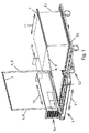
- FIG. 1 shows the basic problem
- a so-called dolly On a transport vehicle 52, a so-called dolly, is a load, in this case, a so-called range 51 - in contrast to, for example a container 50, as in about FIG. 8c is shown - in the form of a rectangular parallelepiped, which is to be moved over in the transverse direction 11 on the loading surface 3 of the container transporter 1.
- the longitudinal direction 10 of the container transporter 1 is defined by the loading surface 3 of the container transporter towering side wall 1a, which is sketched here only slightly and in which are usually the hydraulic, electrical and electronic components and the drive motor.
- FIG. 1 now shows a first way, such as a load - in the following is always the concrete form of the load, so pallet or container, called without the invention thereby limited to any form of load - can be moved over.
- the container transporter 1 has a transfer device 4, which comprises two transfer arms 9 'extending in front and behind the pallet 51 in the transverse direction 11, and which can be pivoted about a horizontal longitudinal axis close to the side wall 1a.
- the takeover arms 9 ' can be positioned in the rest position either upright near the side wall 1a or recessed lying flat below the loading area 3 in the chassis of the container transporter 1, provided that they do not project laterally beyond the base area of the container transporter 1 in the non-telescoped position.
- takeover arms 9 The free ends of the takeover arms 9 'are connected via a connecting rod, which engages as a takeover hook 7 behind the pallet 51, which is not necessary, as well as individual of each takeover arm 9' querstrebende takeover hook to serve the same purpose.
- the takeover hook 7 can now engage behind the pallet 51 by the upright takeover arms 9 'are folded down as far from the upright position and thereby extended in the longitudinal extent that their takeover hook 7, in this case the connecting crossbar , located behind the back of the pallet 51 facing away from the container transporter 1.
- the pallet 51 is then at least partially pulled onto the container transporter 1, until there existing fixed transport elements acting in the transverse direction - usually adjustable in height transport belt - contact with the underside of the pallet 51 and move on.
- the takeover arms 9 'sunk in the ground under the bed 3 they can be extended from there by telescoping the side of the pallet 51 - if necessary after slight swinging - then at their ends no continuous crossbar between the two Takeover arms 9 'may be present but single, to the longitudinal axis of the takeover rod 9' also rotatable takeover hooks, which are folded down only behind the pallet 51 and then engage behind.
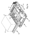
- FIG. 2b shows - horizontally extendable through correspondingly arranged openings in the surrounding chassis frame 27 so that they drive with their free ends by corresponding clearances in the transport vehicle 52 under the bottom of the pallet 51 forward.
- pivotable takeover hooks 7 are arranged about a horizontal axis, which in the upwardly activated direction by means of z. B. spring force are biased, but when starting to the pallet 51, automatically fold, as in Figure 2c see, and only behind the pallet 51 fold up again, as in Figure 2d seen.
- the transport vehicle 52 on which the goods to be transferred - not shown - load is positioned on the front side of the container transporter 1.
- the transfer device 4 consists of two mutually spaced, in the longitudinal direction 10 from the front side projecting Takeover arms 9, in each of which two drivable, pivotable takeover rollers 6 are arranged.
- a lever linkage 28 for example a parallelogram, from the rest position, in which they are below the level of the bed 3, are pivoted upwards and outwards, so that they the bottom of one on the transport vehicle 52nd Contact dormant cargo through there existing breakthroughs and push by driving this takeover rollers 6 on the container transporter 1.
- the lever linkage 28 consists of individual levers, which are attached to the transfer arm 9 with its lower end and from there usually obliquely upwardly and are connected at its upper end with one of the two in the desired transport direction successively arranged take-over rollers 6, which in turn are coupled by a cross brace, which gives a total of a parallelogram.
- Figure 3c a solution in which the frame of the transport vehicle 52 has recesses therefor, so that the takeover arm 9 'here can be made telescopic and horizontally or slightly upwards in the transport vehicle 52 can be moved into to contact with the ground of not illustrated load.
- the drivable takeover roller 6 is attached to the free end of a lever 12a, which extends under the loading surface 3 and on the center in the middle of a second lever 12b hingedly engages, the other end on the underside of the chassis from the outer edge set back pivotally is attached to the container transporter 1.
- the other free end of the lever 12a of the lever linkage 12 is connected to a working cylinder, such as a hydraulic cylinder 19, which runs in the desired direction of movement for the cargo under the chassis of the container transporter 1 and the lever 12a in the direction outside the base of the Container transporter 1 moves. Because of the first obliquely inwardly down and finally obliquely outwardly downwardly facing second lever 12b passes through the takeover roller 6 while a trough-shaped path from under the container transporter 1 to below the transport vehicle 52nd
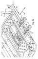
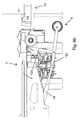
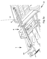
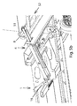
- FIG. 5 shows a solution in which the bottom of the load in turn grasped through openings 54 in the loading area 53 of the transport vehicle 52, but is pulled by frictional by a takeover friction pad 8 is disposed on a telescopic takeover arm 9 ', and the acquisition -Arm 9 'can also be easily pivoted about a transverse axis:
- the takeover arm 9 extends under the loading area 3 of the container transporter 1 and extends through the peripheral side frame rising obliquely upward addition, at least in its extended position, as in FIG. 5a shown. At its free end there is an upturned friction pad 8 directed upwards against the bottom of the load, such as a pallet 51.
- the bottom of the pallet 51 also raise and pull, the takeover arm 9 'in its central region articulated to the chassis of the container transporter 1 is mounted, and directed at its rear end by a hydraulic cylinder 19 slightly downwards applied.
- a hydraulic cylinder 19 By extending the hydraulic cylinder thereby the front end of the takeover arm 9 'and thus the pallet 51 is raised, wherein the friction pad 8 course again by appropriate - in the Figures 5 not shown - openings 54 of the bed 53 of the transport vehicle 52 passes through.
- the telescopic arm 9 'in its deactivated position does not protrude beyond the base of the container transporter 1 to the outside.
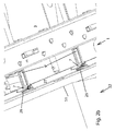
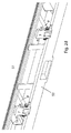
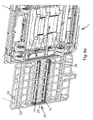
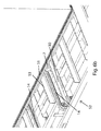
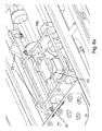
- the transfer device 55 consists of two adjacent, circulating in a vertical plane chains 14, the upper run is just below the level of the bed 53 of the transport vehicle 52, as the view from below at FIG. 6a shows.
- the two chains 14 are functionally unified by a connecting rod 29 which is located at the lower run.
- a takeover arm 9 ' which is telescopic, and is located in the deactivated retracted state entirely within the base of the container transporter 1.
- the telescope When extending the telescope, however, it extends through a corresponding recess in the chassis under the transport vehicle 52 and presses with its free end and a fork arranged there transversely against the connecting rod 29 between the two chains 14 and can push them away from the container transporter to the outer edge of the transport vehicle 52nd
- a takeover hook 7 is attached to each chain 14, which has an upstanding leg which engages the rear edge of the pallet 51 in this movement of the chain 14 and this forward, so towards container carrier 1 pushes.
- the pick-up hook 7, which is pivotable with respect to the chain 14, is held by only one part of its path of movement through a coving 30 on which a peg 31, which projects away from the hook, rests.
- FIG. 6c shows a solution in which the transfer device 55 in the bottom of the transport vehicle 52 in a vertical plane revolving, juxtaposed conveyor belt 13, on the upper run the cargo, such as the pallet 51, either constantly rests or only after pushing up the transfer device 55th
- Both the driving of the belt 13 in the desired direction of movement of the pallet 51 and possibly their high pressures is in turn by the transfer device 4 in the bottom of the container transporter 1, for example, the telescopic, extendable acquisition arm 9 'causes, of which only a short Piece is visible.
- FIGS. 7a show a transfer device 55 on the transport vehicle 52, which is activated and driven by a transfer device 4 from the container transporter 1, for example, the telescopic, extendable transfer arm 9 ':
- the loading surface 53 of the transport vehicle 52 is formed by two adjacent horizontally disposed turntables 16a, b, which are each about a point, usually its center, rotationally driven, always in opposite directions of rotation to each other, which each by a corresponding circulating on the bottom Chain 14a, b can be reached, which meshes with a pinion in the fulcrum of the hubs 16a, b.
- the chains 14a, b are in turn coupled via a connecting rod 29 in their movement, which is displaced from the already described extendable transfer arm 9 ', which is the transfer device 4 of the container transporter 1.
- pallet 51 is by a rotational movement in the adjacent area of the turntables 16a, b is directed towards the container transporter 1, cause a movement of the pallet 51 on the container transporter 1.
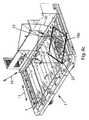
- FIGS. 8 and 9 In contrast to the above figures are concerned FIGS. 8 and 9 with the problem of rotation of a load, which is already on the container transporter 1, about its vertical axis, such as in FIG. 8c seen.
- the containers 50 are transferred to and from the container transporter 1 as a rule only in the longitudinal direction 10 and stand with their longitudinal extent in the transverse direction 11 of the container transporter. 1
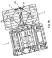
- the rotating device 17 comprises a first lifting frame 18 a, which is adjustable in height and rotatable about its vertical axis 20.
- a container 50 In the lowered state, it is located below the level of the loading area 3 of the container transporter 1. In this deactivated position, a container 50 can be positioned on the loading area 3 just above the lifting frame 18a.
- the lifting frame 18a is raised above the level of the bed 3, and thus raises the container 50 with rotates with the Container around its vertical axis and lowers in the desired rotational position of the container 50 again to a level below the loading area 3, on which now the container 50 rests again, but at z. B. rotated 90 °.
- the lifting of the lifting frame 18a can according to FIG. 8a done by a hydraulic cylinder 19, but with a non-circular, preferably poligonen longitudinal guide to avoid unwanted rotational movements about the longitudinal axis of the hydraulic cylinder, while in the solution of the FIG. 8b for lifting a scissor linkage 21 between the lifting frame 18a and a turntable 32 is used.
- the turntable 32 in which an unillustrated pinion can engage, the scissors linkage 21 or the hydraulic cylinder 19 and thus the entire lifting frame 18 a is rotated about the vertical axis 20 by the desired angle.
- FIGS. 8a and 8b also show, the openings between the struts of the lifting frame 18a are so large and positioned so that in the lowered state, the transport rollers 2 of the loading area 3 of the container transporter 1 protrude through the lifting frame 18a upwards.
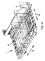
- the lengthwise longitudinal stops 23 are raised from the loading surface when the container 50 is pulled over, and the container 50 is moved up to the stop.
- the container 50 In order to achieve a correct positioning in the transverse direction 11, the container 50 must also be moved in the transverse direction 11 until it stops at transverse transverse stops 11 acting in the transverse direction 11 which, for example, in FIG. 9b are recognizable.
- a second lifting frame 18b for the same purpose next to the first lifting frame 18a, a second lifting frame 18b, but closer to the side wall 1a, arranged, which is not rotatable about its vertical axis. Instead, this second lifting frame 18b carries over its top projecting transport rollers 2 ', which are also driven.
- the container 50 resting on only the second lifting frame 18b or on both lifting frames 18a, b can contact the underside of the container 50 by raising the second lifting frame 18b and contacting its transport rollers 2 '- which are arranged so that they can only transport in the transverse direction 11 Lift and move this in the transverse direction 11 up to the transverse stops 22 zoom. Subsequently, this second lifting frame 18b is lowered and the first lifting frame 18a comes into action as previously described.
Landscapes
- Engineering & Computer Science (AREA)
- Mechanical Engineering (AREA)
- Aviation & Aerospace Engineering (AREA)
- Loading Or Unloading Of Vehicles (AREA)
- Intermediate Stations On Conveyors (AREA)
Priority Applications (1)
| Application Number | Priority Date | Filing Date | Title |
|---|---|---|---|
| SI201131573T SI2390185T1 (sl) | 2010-05-31 | 2011-04-04 | Transporter za zabojnike |
Applications Claiming Priority (1)
| Application Number | Priority Date | Filing Date | Title |
|---|---|---|---|
| DE102010022081.7A DE102010022081B4 (de) | 2010-05-31 | 2010-05-31 | Containertransporter |
Publications (3)
| Publication Number | Publication Date |
|---|---|
| EP2390185A2 true EP2390185A2 (fr) | 2011-11-30 |
| EP2390185A3 EP2390185A3 (fr) | 2014-03-26 |
| EP2390185B1 EP2390185B1 (fr) | 2018-06-13 |
Family
ID=44511775
Family Applications (1)
| Application Number | Title | Priority Date | Filing Date |
|---|---|---|---|
| EP11160980.6A Not-in-force EP2390185B1 (fr) | 2010-05-31 | 2011-04-04 | Transporteur de conteneur |
Country Status (3)
| Country | Link |
|---|---|
| EP (1) | EP2390185B1 (fr) |
| DE (1) | DE102010022081B4 (fr) |
| SI (1) | SI2390185T1 (fr) |
Cited By (6)
| Publication number | Priority date | Publication date | Assignee | Title |
|---|---|---|---|---|
| EP2581312A1 (fr) * | 2011-10-13 | 2013-04-17 | MULAG Fahrzeugwerk | Transporteur de conteneur |
| CN111114819A (zh) * | 2020-03-12 | 2020-05-08 | 眉山德鑫航空设备股份有限公司 | 一种锁定货物专用拖车挂钩装置 |
| CN112607045A (zh) * | 2020-12-18 | 2021-04-06 | 淄博询知方技术开发有限公司 | 一种智慧农业用可收纳的植保无人机降落平台 |
| US11511981B2 (en) * | 2020-09-01 | 2022-11-29 | Urbineer Inc | Robotic powered cargo handling system |
| US20240002175A1 (en) * | 2022-07-01 | 2024-01-04 | Kevin D. McGushion | Methods, Systems and Devices for Efficient and Rapid Autonomous Delivery of Goods |
| CN119858810A (zh) * | 2025-03-21 | 2025-04-22 | 厦门艾科曼智能装备有限公司 | 一种集装箱货物转运平台 |
Families Citing this family (2)
| Publication number | Priority date | Publication date | Assignee | Title |
|---|---|---|---|---|
| DE102019104051A1 (de) * | 2019-02-18 | 2020-08-20 | A&A Logistik-Equipment GmbH & Co. KG | Fahrerloses Transportfahrzeug |
| DE102019109342A1 (de) * | 2019-04-09 | 2020-10-15 | Telejet Kommunikations Gmbh | Flächenlager sowie Verfahren zum Ein- und Auslagern von Norm-Behältern darin |
Family Cites Families (12)
| Publication number | Priority date | Publication date | Assignee | Title |
|---|---|---|---|---|
| US3279631A (en) * | 1964-04-02 | 1966-10-18 | American Sugar | Transfer trailer |
| US3435969A (en) * | 1966-04-11 | 1969-04-01 | Domino Sugar Co | Cargo handling apparatus |
| US3447665A (en) * | 1967-06-15 | 1969-06-03 | Cragomatic Inc | Cargo load carrier enabling universal movement of cargo load thereon and thereover |
| US3655075A (en) * | 1967-07-21 | 1972-04-11 | Dorr Oliver Inc | Cargo handling |
| DE2131867C3 (de) * | 1971-06-26 | 1974-01-17 | Mannesmann Ag, 4000 Duesseldorf | Winkelfbrdertisch, insbesondere für Flugzeugfrachteinheiten |
| US3854610A (en) * | 1973-04-09 | 1974-12-17 | Cochran Boothe Airport Syst | Freight transporter and loader for aircraft |
| DE7733457U1 (de) * | 1977-10-29 | 1978-02-02 | Braunschweigische Maschinenbauanstalt, 3300 Braunschweig | Foerderplattform fuer hubbuehnen |
| US4312619A (en) * | 1979-07-19 | 1982-01-26 | Fmc Corporation | Aircraft cargo loading method and apparatus |
| DE3821246A1 (de) * | 1988-06-23 | 1989-12-28 | Falkenried Fahrzeug Gmbh | Flugfeld-transportanordnung |
| CH678045A5 (fr) * | 1989-02-28 | 1991-07-31 | Frech Ag Geb | |
| US5184366A (en) * | 1991-01-31 | 1993-02-09 | Mcdonnell Douglas Corporation | Aircraft cargo handling system |
| DE102010017572A1 (de) * | 2010-06-24 | 2011-12-29 | Thomas Breuer | Greifapparat |
-
2010
- 2010-05-31 DE DE102010022081.7A patent/DE102010022081B4/de not_active Expired - Fee Related
-
2011
- 2011-04-04 SI SI201131573T patent/SI2390185T1/sl unknown
- 2011-04-04 EP EP11160980.6A patent/EP2390185B1/fr not_active Not-in-force
Non-Patent Citations (1)
| Title |
|---|
| None |
Cited By (6)
| Publication number | Priority date | Publication date | Assignee | Title |
|---|---|---|---|---|
| EP2581312A1 (fr) * | 2011-10-13 | 2013-04-17 | MULAG Fahrzeugwerk | Transporteur de conteneur |
| CN111114819A (zh) * | 2020-03-12 | 2020-05-08 | 眉山德鑫航空设备股份有限公司 | 一种锁定货物专用拖车挂钩装置 |
| US11511981B2 (en) * | 2020-09-01 | 2022-11-29 | Urbineer Inc | Robotic powered cargo handling system |
| CN112607045A (zh) * | 2020-12-18 | 2021-04-06 | 淄博询知方技术开发有限公司 | 一种智慧农业用可收纳的植保无人机降落平台 |
| US20240002175A1 (en) * | 2022-07-01 | 2024-01-04 | Kevin D. McGushion | Methods, Systems and Devices for Efficient and Rapid Autonomous Delivery of Goods |
| CN119858810A (zh) * | 2025-03-21 | 2025-04-22 | 厦门艾科曼智能装备有限公司 | 一种集装箱货物转运平台 |
Also Published As
| Publication number | Publication date |
|---|---|
| EP2390185A3 (fr) | 2014-03-26 |
| EP2390185B1 (fr) | 2018-06-13 |
| SI2390185T1 (sl) | 2018-10-30 |
| DE102010022081A1 (de) | 2011-12-01 |
| DE102010022081B4 (de) | 2016-03-17 |
Similar Documents
| Publication | Publication Date | Title |
|---|---|---|
| EP2390185B1 (fr) | Transporteur de conteneur | |
| EP2885199B1 (fr) | Remorque de train de remorques | |
| DE2516455C3 (de) | Vorrichtung zum Be- und Entladen von Stückgütern | |
| DE69306480T2 (de) | Werkstücktransportsystem mit Palettentransportgerät | |
| EP2443005B1 (fr) | Systeme de transport | |
| EP2100831A1 (fr) | Véhicule de transport pour palettes et système de transport | |
| DE4307254A1 (de) | Lastenverladekran | |
| DE1655728A1 (de) | Vorrichtung zum Heben und Transportieren von Lasten | |
| DE1784146C3 (de) | Mehrstöckige Speichereinrichtung für Kraftfahrzeuge und andere Gegenstände | |
| DE102009026701A1 (de) | Verfahren zum gleichzeitigen Beladen einer Ladefläche eines Lastfahrzeugs mit einer Vielzahl von Güterpaletten und Lademaschine dafür | |
| DE102022132923B4 (de) | Logistiksystem | |
| EP0666209B1 (fr) | Chariot de transport, en particulier conteneur roulant comportant des pieds de support retractables | |
| DE3109793A1 (de) | Ladeapparat | |
| EP3571354B1 (fr) | Dispositif de pose de pont destiné à poser un pont en particulier d'une seule pièce | |
| DE102011115924B4 (de) | Containertransporter und Verfahren zum automatischen Herüberbewegen eines Ladegutes | |
| EP1988053A2 (fr) | Convoyeurs au sol pour transporter des transconteneurs | |
| WO2013167315A1 (fr) | Dispositif de levage ainsi que dispositif de transbordement de marchandises et procédé de transbordement de marchandises à l'aide d'au moins un tel dispositif de levage | |
| DE202019104060U1 (de) | Vorrichtung zum Anheben und Absenken eines schweren Gegenstandes sowie deren Verwendung | |
| DE102012104235B4 (de) | Verriegelungseinrichtung zum Sichern und/oder Führen mindestens eines Frachtstücks | |
| DE1277038B (de) | Fahrzeug fuer die Befoerderung grosser Einzellasten | |
| DE926058C (de) | Vorrichtung zum Transport insbesondere schwerer Lasten durch ein mit Hubzinken versehenes Foerderfahrzeug, z. B. Hubstapler | |
| EP1862405A1 (fr) | Procédé destiné à saisir une marchandise à l'aide d'éléments de préhension dans un dispositif de stockage et de déstockage et dispositif correspondant | |
| EP4197944B1 (fr) | Installation de chargement et de déchargement de matière en vrac et procédé associé | |
| AT330660B (de) | Einrichtung fur das pulkweise beladen von strassenfahrzeugen | |
| DE3231963A1 (de) | Verrriegelungseinrichtung fuer einen auf ein fahrzeug auf- und abladbaren und auf diesem kippbaren container |
Legal Events
| Date | Code | Title | Description |
|---|---|---|---|
| AK | Designated contracting states |
Kind code of ref document: A2 Designated state(s): AL AT BE BG CH CY CZ DE DK EE ES FI FR GB GR HR HU IE IS IT LI LT LU LV MC MK MT NL NO PL PT RO RS SE SI SK SM TR |
|
| AX | Request for extension of the european patent |
Extension state: BA ME |
|
| PUAI | Public reference made under article 153(3) epc to a published international application that has entered the european phase |
Free format text: ORIGINAL CODE: 0009012 |
|
| PUAL | Search report despatched |
Free format text: ORIGINAL CODE: 0009013 |
|
| AK | Designated contracting states |
Kind code of ref document: A3 Designated state(s): AL AT BE BG CH CY CZ DE DK EE ES FI FR GB GR HR HU IE IS IT LI LT LU LV MC MK MT NL NO PL PT RO RS SE SI SK SM TR |
|
| AX | Request for extension of the european patent |
Extension state: BA ME |
|
| RIC1 | Information provided on ipc code assigned before grant |
Ipc: B64F 1/32 20060101AFI20140220BHEP |
|
| 17P | Request for examination filed |
Effective date: 20140925 |
|
| RBV | Designated contracting states (corrected) |
Designated state(s): AL AT BE BG CH CY CZ DE DK EE ES FI FR GB GR HR HU IE IS IT LI LT LU LV MC MK MT NL NO PL PT RO RS SE SI SK SM TR |
|
| STAA | Information on the status of an ep patent application or granted ep patent |
Free format text: STATUS: EXAMINATION IS IN PROGRESS |
|
| 17Q | First examination report despatched |
Effective date: 20170324 |
|
| GRAP | Despatch of communication of intention to grant a patent |
Free format text: ORIGINAL CODE: EPIDOSNIGR1 |
|
| STAA | Information on the status of an ep patent application or granted ep patent |
Free format text: STATUS: GRANT OF PATENT IS INTENDED |
|
| INTG | Intention to grant announced |
Effective date: 20171214 |
|
| GRAS | Grant fee paid |
Free format text: ORIGINAL CODE: EPIDOSNIGR3 |
|
| GRAA | (expected) grant |
Free format text: ORIGINAL CODE: 0009210 |
|
| STAA | Information on the status of an ep patent application or granted ep patent |
Free format text: STATUS: THE PATENT HAS BEEN GRANTED |
|
| AK | Designated contracting states |
Kind code of ref document: B1 Designated state(s): AL AT BE BG CH CY CZ DE DK EE ES FI FR GB GR HR HU IE IS IT LI LT LU LV MC MK MT NL NO PL PT RO RS SE SI SK SM TR |
|
| REG | Reference to a national code |
Ref country code: GB Ref legal event code: FG4D Free format text: NOT ENGLISH |
|
| REG | Reference to a national code |
Ref country code: CH Ref legal event code: EP Ref country code: AT Ref legal event code: REF Ref document number: 1008236 Country of ref document: AT Kind code of ref document: T Effective date: 20180615 |
|
| REG | Reference to a national code |
Ref country code: IE Ref legal event code: FG4D Free format text: LANGUAGE OF EP DOCUMENT: GERMAN |
|
| REG | Reference to a national code |
Ref country code: DE Ref legal event code: R096 Ref document number: 502011014316 Country of ref document: DE |
|
| REG | Reference to a national code |
Ref country code: NL Ref legal event code: FP |
|
| REG | Reference to a national code |
Ref country code: LT Ref legal event code: MG4D |
|
| PG25 | Lapsed in a contracting state [announced via postgrant information from national office to epo] |
Ref country code: NO Free format text: LAPSE BECAUSE OF FAILURE TO SUBMIT A TRANSLATION OF THE DESCRIPTION OR TO PAY THE FEE WITHIN THE PRESCRIBED TIME-LIMIT Effective date: 20180913 Ref country code: CY Free format text: LAPSE BECAUSE OF FAILURE TO SUBMIT A TRANSLATION OF THE DESCRIPTION OR TO PAY THE FEE WITHIN THE PRESCRIBED TIME-LIMIT Effective date: 20180613 Ref country code: ES Free format text: LAPSE BECAUSE OF FAILURE TO SUBMIT A TRANSLATION OF THE DESCRIPTION OR TO PAY THE FEE WITHIN THE PRESCRIBED TIME-LIMIT Effective date: 20180613 Ref country code: LT Free format text: LAPSE BECAUSE OF FAILURE TO SUBMIT A TRANSLATION OF THE DESCRIPTION OR TO PAY THE FEE WITHIN THE PRESCRIBED TIME-LIMIT Effective date: 20180613 Ref country code: SE Free format text: LAPSE BECAUSE OF FAILURE TO SUBMIT A TRANSLATION OF THE DESCRIPTION OR TO PAY THE FEE WITHIN THE PRESCRIBED TIME-LIMIT Effective date: 20180613 Ref country code: FI Free format text: LAPSE BECAUSE OF FAILURE TO SUBMIT A TRANSLATION OF THE DESCRIPTION OR TO PAY THE FEE WITHIN THE PRESCRIBED TIME-LIMIT Effective date: 20180613 Ref country code: BG Free format text: LAPSE BECAUSE OF FAILURE TO SUBMIT A TRANSLATION OF THE DESCRIPTION OR TO PAY THE FEE WITHIN THE PRESCRIBED TIME-LIMIT Effective date: 20180913 |
|
| PG25 | Lapsed in a contracting state [announced via postgrant information from national office to epo] |
Ref country code: LV Free format text: LAPSE BECAUSE OF FAILURE TO SUBMIT A TRANSLATION OF THE DESCRIPTION OR TO PAY THE FEE WITHIN THE PRESCRIBED TIME-LIMIT Effective date: 20180613 Ref country code: RS Free format text: LAPSE BECAUSE OF FAILURE TO SUBMIT A TRANSLATION OF THE DESCRIPTION OR TO PAY THE FEE WITHIN THE PRESCRIBED TIME-LIMIT Effective date: 20180613 Ref country code: GR Free format text: LAPSE BECAUSE OF FAILURE TO SUBMIT A TRANSLATION OF THE DESCRIPTION OR TO PAY THE FEE WITHIN THE PRESCRIBED TIME-LIMIT Effective date: 20180914 Ref country code: HR Free format text: LAPSE BECAUSE OF FAILURE TO SUBMIT A TRANSLATION OF THE DESCRIPTION OR TO PAY THE FEE WITHIN THE PRESCRIBED TIME-LIMIT Effective date: 20180613 |
|
| PG25 | Lapsed in a contracting state [announced via postgrant information from national office to epo] |
Ref country code: PL Free format text: LAPSE BECAUSE OF FAILURE TO SUBMIT A TRANSLATION OF THE DESCRIPTION OR TO PAY THE FEE WITHIN THE PRESCRIBED TIME-LIMIT Effective date: 20180613 Ref country code: IS Free format text: LAPSE BECAUSE OF FAILURE TO SUBMIT A TRANSLATION OF THE DESCRIPTION OR TO PAY THE FEE WITHIN THE PRESCRIBED TIME-LIMIT Effective date: 20181013 Ref country code: SK Free format text: LAPSE BECAUSE OF FAILURE TO SUBMIT A TRANSLATION OF THE DESCRIPTION OR TO PAY THE FEE WITHIN THE PRESCRIBED TIME-LIMIT Effective date: 20180613 Ref country code: RO Free format text: LAPSE BECAUSE OF FAILURE TO SUBMIT A TRANSLATION OF THE DESCRIPTION OR TO PAY THE FEE WITHIN THE PRESCRIBED TIME-LIMIT Effective date: 20180613 Ref country code: CZ Free format text: LAPSE BECAUSE OF FAILURE TO SUBMIT A TRANSLATION OF THE DESCRIPTION OR TO PAY THE FEE WITHIN THE PRESCRIBED TIME-LIMIT Effective date: 20180613 Ref country code: EE Free format text: LAPSE BECAUSE OF FAILURE TO SUBMIT A TRANSLATION OF THE DESCRIPTION OR TO PAY THE FEE WITHIN THE PRESCRIBED TIME-LIMIT Effective date: 20180613 |
|
| PG25 | Lapsed in a contracting state [announced via postgrant information from national office to epo] |
Ref country code: SM Free format text: LAPSE BECAUSE OF FAILURE TO SUBMIT A TRANSLATION OF THE DESCRIPTION OR TO PAY THE FEE WITHIN THE PRESCRIBED TIME-LIMIT Effective date: 20180613 Ref country code: IT Free format text: LAPSE BECAUSE OF FAILURE TO SUBMIT A TRANSLATION OF THE DESCRIPTION OR TO PAY THE FEE WITHIN THE PRESCRIBED TIME-LIMIT Effective date: 20180613 |
|
| REG | Reference to a national code |
Ref country code: DE Ref legal event code: R097 Ref document number: 502011014316 Country of ref document: DE |
|
| PLBE | No opposition filed within time limit |
Free format text: ORIGINAL CODE: 0009261 |
|
| STAA | Information on the status of an ep patent application or granted ep patent |
Free format text: STATUS: NO OPPOSITION FILED WITHIN TIME LIMIT |
|
| 26N | No opposition filed |
Effective date: 20190314 |
|
| PG25 | Lapsed in a contracting state [announced via postgrant information from national office to epo] |
Ref country code: DK Free format text: LAPSE BECAUSE OF FAILURE TO SUBMIT A TRANSLATION OF THE DESCRIPTION OR TO PAY THE FEE WITHIN THE PRESCRIBED TIME-LIMIT Effective date: 20180613 |
|
| PGFP | Annual fee paid to national office [announced via postgrant information from national office to epo] |
Ref country code: LU Payment date: 20190418 Year of fee payment: 9 Ref country code: NL Payment date: 20190418 Year of fee payment: 9 |
|
| PGFP | Annual fee paid to national office [announced via postgrant information from national office to epo] |
Ref country code: TR Payment date: 20190425 Year of fee payment: 9 Ref country code: SI Payment date: 20190425 Year of fee payment: 9 Ref country code: BE Payment date: 20190418 Year of fee payment: 9 Ref country code: FR Payment date: 20190423 Year of fee payment: 9 |
|
| PG25 | Lapsed in a contracting state [announced via postgrant information from national office to epo] |
Ref country code: AL Free format text: LAPSE BECAUSE OF FAILURE TO SUBMIT A TRANSLATION OF THE DESCRIPTION OR TO PAY THE FEE WITHIN THE PRESCRIBED TIME-LIMIT Effective date: 20180613 |
|
| REG | Reference to a national code |
Ref country code: CH Ref legal event code: PL |
|
| GBPC | Gb: european patent ceased through non-payment of renewal fee |
Effective date: 20190404 |
|
| PG25 | Lapsed in a contracting state [announced via postgrant information from national office to epo] |
Ref country code: MC Free format text: LAPSE BECAUSE OF FAILURE TO SUBMIT A TRANSLATION OF THE DESCRIPTION OR TO PAY THE FEE WITHIN THE PRESCRIBED TIME-LIMIT Effective date: 20180613 |
|
| PG25 | Lapsed in a contracting state [announced via postgrant information from national office to epo] |
Ref country code: CH Free format text: LAPSE BECAUSE OF NON-PAYMENT OF DUE FEES Effective date: 20190430 Ref country code: LI Free format text: LAPSE BECAUSE OF NON-PAYMENT OF DUE FEES Effective date: 20190430 Ref country code: GB Free format text: LAPSE BECAUSE OF NON-PAYMENT OF DUE FEES Effective date: 20190404 |
|
| PG25 | Lapsed in a contracting state [announced via postgrant information from national office to epo] |
Ref country code: IE Free format text: LAPSE BECAUSE OF NON-PAYMENT OF DUE FEES Effective date: 20190404 |
|
| PG25 | Lapsed in a contracting state [announced via postgrant information from national office to epo] |
Ref country code: PT Free format text: LAPSE BECAUSE OF FAILURE TO SUBMIT A TRANSLATION OF THE DESCRIPTION OR TO PAY THE FEE WITHIN THE PRESCRIBED TIME-LIMIT Effective date: 20181015 |
|
| PGFP | Annual fee paid to national office [announced via postgrant information from national office to epo] |
Ref country code: DE Payment date: 20200430 Year of fee payment: 10 |
|
| REG | Reference to a national code |
Ref country code: AT Ref legal event code: MM01 Ref document number: 1008236 Country of ref document: AT Kind code of ref document: T Effective date: 20190404 |
|
| PG25 | Lapsed in a contracting state [announced via postgrant information from national office to epo] |
Ref country code: AT Free format text: LAPSE BECAUSE OF NON-PAYMENT OF DUE FEES Effective date: 20190404 |
|
| REG | Reference to a national code |
Ref country code: NL Ref legal event code: MM Effective date: 20200501 |
|
| PG25 | Lapsed in a contracting state [announced via postgrant information from national office to epo] |
Ref country code: FR Free format text: LAPSE BECAUSE OF NON-PAYMENT OF DUE FEES Effective date: 20200430 Ref country code: LU Free format text: LAPSE BECAUSE OF NON-PAYMENT OF DUE FEES Effective date: 20200404 |
|
| REG | Reference to a national code |
Ref country code: BE Ref legal event code: MM Effective date: 20200430 |
|
| PG25 | Lapsed in a contracting state [announced via postgrant information from national office to epo] |
Ref country code: BE Free format text: LAPSE BECAUSE OF NON-PAYMENT OF DUE FEES Effective date: 20200430 |
|
| PG25 | Lapsed in a contracting state [announced via postgrant information from national office to epo] |
Ref country code: NL Free format text: LAPSE BECAUSE OF NON-PAYMENT OF DUE FEES Effective date: 20200501 |
|
| PG25 | Lapsed in a contracting state [announced via postgrant information from national office to epo] |
Ref country code: MT Free format text: LAPSE BECAUSE OF FAILURE TO SUBMIT A TRANSLATION OF THE DESCRIPTION OR TO PAY THE FEE WITHIN THE PRESCRIBED TIME-LIMIT Effective date: 20180613 Ref country code: HU Free format text: LAPSE BECAUSE OF FAILURE TO SUBMIT A TRANSLATION OF THE DESCRIPTION OR TO PAY THE FEE WITHIN THE PRESCRIBED TIME-LIMIT; INVALID AB INITIO Effective date: 20110404 |
|
| PG25 | Lapsed in a contracting state [announced via postgrant information from national office to epo] |
Ref country code: SI Free format text: LAPSE BECAUSE OF NON-PAYMENT OF DUE FEES Effective date: 20200405 |
|
| REG | Reference to a national code |
Ref country code: SI Ref legal event code: KO00 Effective date: 20210810 |
|
| REG | Reference to a national code |
Ref country code: DE Ref legal event code: R119 Ref document number: 502011014316 Country of ref document: DE |
|
| PG25 | Lapsed in a contracting state [announced via postgrant information from national office to epo] |
Ref country code: DE Free format text: LAPSE BECAUSE OF NON-PAYMENT OF DUE FEES Effective date: 20211103 |
|
| PG25 | Lapsed in a contracting state [announced via postgrant information from national office to epo] |
Ref country code: TR Free format text: LAPSE BECAUSE OF NON-PAYMENT OF DUE FEES Effective date: 20200404 Ref country code: MK Free format text: LAPSE BECAUSE OF FAILURE TO SUBMIT A TRANSLATION OF THE DESCRIPTION OR TO PAY THE FEE WITHIN THE PRESCRIBED TIME-LIMIT Effective date: 20180613 |
|
| P01 | Opt-out of the competence of the unified patent court (upc) registered |
Effective date: 20230526 |