EP2390301A2 - Installation de réacteur et procédé de production d'un produit de matière solide enrichi en carbone à l'aide d'une augmentation de la teneur en carbone - Google Patents
Installation de réacteur et procédé de production d'un produit de matière solide enrichi en carbone à l'aide d'une augmentation de la teneur en carbone Download PDFInfo
- Publication number
- EP2390301A2 EP2390301A2 EP11167830A EP11167830A EP2390301A2 EP 2390301 A2 EP2390301 A2 EP 2390301A2 EP 11167830 A EP11167830 A EP 11167830A EP 11167830 A EP11167830 A EP 11167830A EP 2390301 A2 EP2390301 A2 EP 2390301A2
- Authority
- EP
- European Patent Office
- Prior art keywords
- reactor
- reaction
- carbon
- reaction fluid
- temperature
- Prior art date
- Legal status (The legal status is an assumption and is not a legal conclusion. Google has not performed a legal analysis and makes no representation as to the accuracy of the status listed.)
- Granted
Links
Images


Classifications
-
- C—CHEMISTRY; METALLURGY
- C10—PETROLEUM, GAS OR COKE INDUSTRIES; TECHNICAL GASES CONTAINING CARBON MONOXIDE; FUELS; LUBRICANTS; PEAT
- C10B—DESTRUCTIVE DISTILLATION OF CARBONACEOUS MATERIALS FOR PRODUCTION OF GAS, COKE, TAR, OR SIMILAR MATERIALS
- C10B53/00—Destructive distillation, specially adapted for particular solid raw materials or solid raw materials in special form
- C10B53/02—Destructive distillation, specially adapted for particular solid raw materials or solid raw materials in special form of cellulose-containing material
-
- C—CHEMISTRY; METALLURGY
- C10—PETROLEUM, GAS OR COKE INDUSTRIES; TECHNICAL GASES CONTAINING CARBON MONOXIDE; FUELS; LUBRICANTS; PEAT
- C10B—DESTRUCTIVE DISTILLATION OF CARBONACEOUS MATERIALS FOR PRODUCTION OF GAS, COKE, TAR, OR SIMILAR MATERIALS
- C10B47/00—Destructive distillation of solid carbonaceous materials with indirect heating, e.g. by external combustion
- C10B47/28—Other processes
- C10B47/32—Other processes in ovens with mechanical conveying means
- C10B47/44—Other processes in ovens with mechanical conveying means with conveyor-screws
-
- C—CHEMISTRY; METALLURGY
- C10—PETROLEUM, GAS OR COKE INDUSTRIES; TECHNICAL GASES CONTAINING CARBON MONOXIDE; FUELS; LUBRICANTS; PEAT
- C10B—DESTRUCTIVE DISTILLATION OF CARBONACEOUS MATERIALS FOR PRODUCTION OF GAS, COKE, TAR, OR SIMILAR MATERIALS
- C10B51/00—Destructive distillation of solid carbonaceous materials by combined direct and indirect heating
-
- C—CHEMISTRY; METALLURGY
- C10—PETROLEUM, GAS OR COKE INDUSTRIES; TECHNICAL GASES CONTAINING CARBON MONOXIDE; FUELS; LUBRICANTS; PEAT
- C10B—DESTRUCTIVE DISTILLATION OF CARBONACEOUS MATERIALS FOR PRODUCTION OF GAS, COKE, TAR, OR SIMILAR MATERIALS
- C10B57/00—Other carbonising or coking processes; Features of destructive distillation processes in general
- C10B57/12—Applying additives during coking
-
- Y—GENERAL TAGGING OF NEW TECHNOLOGICAL DEVELOPMENTS; GENERAL TAGGING OF CROSS-SECTIONAL TECHNOLOGIES SPANNING OVER SEVERAL SECTIONS OF THE IPC; TECHNICAL SUBJECTS COVERED BY FORMER USPC CROSS-REFERENCE ART COLLECTIONS [XRACs] AND DIGESTS
- Y02—TECHNOLOGIES OR APPLICATIONS FOR MITIGATION OR ADAPTATION AGAINST CLIMATE CHANGE
- Y02E—REDUCTION OF GREENHOUSE GAS [GHG] EMISSIONS, RELATED TO ENERGY GENERATION, TRANSMISSION OR DISTRIBUTION
- Y02E50/00—Technologies for the production of fuel of non-fossil origin
- Y02E50/10—Biofuels, e.g. bio-diesel
-
- Y—GENERAL TAGGING OF NEW TECHNOLOGICAL DEVELOPMENTS; GENERAL TAGGING OF CROSS-SECTIONAL TECHNOLOGIES SPANNING OVER SEVERAL SECTIONS OF THE IPC; TECHNICAL SUBJECTS COVERED BY FORMER USPC CROSS-REFERENCE ART COLLECTIONS [XRACs] AND DIGESTS
- Y02—TECHNOLOGIES OR APPLICATIONS FOR MITIGATION OR ADAPTATION AGAINST CLIMATE CHANGE
- Y02E—REDUCTION OF GREENHOUSE GAS [GHG] EMISSIONS, RELATED TO ENERGY GENERATION, TRANSMISSION OR DISTRIBUTION
- Y02E50/00—Technologies for the production of fuel of non-fossil origin
- Y02E50/30—Fuel from waste, e.g. synthetic alcohol or diesel
Definitions
- the invention relates to a reactor plant and a process for producing a carbon-enriched solid product by increasing the carbon content and reducing the oxygen content.
- the rapid pyrolysis process was developed, in which the carbonaceous material is suddenly heated to over 500 ° C with the exclusion of oxygen. The material decomposes into predominantly volatile components. These are transported by a low-reaction carrier gas from the reactor in a condenser and liquefied to "bio-oil". Like in the CA 02639022 A1 In this case, superheated steam can be used as the carrier gas under high pressure, wherein advantageously the yield of bio-oil can be further increased.
- the conversion of the carbonaceous material is discontinuous, in a so-called batch process.
- the DE 20 2008 012 419 U1 discloses a typical plant for hydrothermal carbonization.
- the carbonization of the biomass takes place in liquid hot pressurized water at a pressure which corresponds at least to the saturation vapor pressure of the water. Typical values are 10-30 bar at temperatures of 160 ° C-210 ° C, with process times ranging from 5 to 14 hours.
- the reaction mixture is homogeneous, ie the biomass is a pasty, mixed with water mass. Intermediates taken from the reactor may be sent for further processing. In this case, still contained water can be separated with a filter device and fed back to the reactor as a water addition. The necessary minimum residence time of the biomass in the reactor is ensured by a corresponding reactor length.
- the reactor Due to the high pressures and temperatures, the introduction of biomass and the discharge of end products and intermediates from the operation and the process control are complex. Due to the high pressure in the reactor, a continuous reaction is not possible, but is carried out quasi-continuously.
- the reactor has successive reactor segments, each having different temperatures, wherein the biomass from a conveyor of one transported into the next reactor segment in which it lingers for a given period of time.
- the object of the present invention is to provide a reactor plant and a process which overcomes the disadvantages of the prior art in producing a carbon-enriched solid product which has an increased carbon content relative to a carbonaceous material being fed.
- a reactor plant and a process for producing a carbon-enriched solid product which comprises increasing the carbon content and reducing the oxygen content of a carbonaceous feedstock in a reactor having a temperature between about 100 ° C to about 450 ° C and a temperature of from about 100 ° C to about 450 ° C Pressure between about 1 bar and about 5 bar prevail, with reaction conditions are chosen so that the reaction fluid remains gaseous during the reaction.
- the residence time of the carbonaceous material in the reactor by means of the conveyor can be controlled so that these minutes is up to a few hours.
- Particularly favorable is a temperature range between 250 ° C and about 400 ° C at a preferred pressure between 1 and 4 bar, more preferably at most 2 bar.
- the reactor system comprises a tempering device with which the desired reaction temperatures can be achieved and, in particular, kept constant.
- the temperature may be adjusted by a reaction fluid, particularly water vapor, which may be "decentralized" and prepared as a supply so that lower energy densities may be necessary compared to other processes.
- a reaction fluid is added to the carbonaceous feedstock via an inlet port, whereby the reaction fluid may advantageously be water vapor or a water vapor mixture.
- the inlet opening may be designed such that it has openings distributed over an inlet region of the reactor, so that a targeted distribution, for example a uniform distribution, of the reaction fluid can be achieved.
- This embodiment is suitable for relatively fine-grained starting materials.
- starting material all organic compounds are conceivable.
- starting materials such as biomass, both lignocellulosic materials, e.g. Wood or straw or green cuttings, but also other sources of carbon, such as residues from the food or beverage industry, the organic household refuse or sewage sludge.
- biomass both lignocellulosic materials, e.g. Wood or straw or green cuttings
- sources of carbon such as residues from the food or beverage industry, the organic household refuse or sewage sludge.
- fossil carbon sources are also conceivable as a starting product.
- the invention also allows a treatment of chemically active sewage sludge with a high mineral content in the sense that an inertization of sewage sludge sets in and odor removal takes place.
- the sewage sludge so treated can then be treated e.g. safe and without odor in the open air.
- a water vapor / carrier gas mixture and / or a water vapor / reaction gas mixture in particular with organic components such as methane, higher alkanes, alkenes, aromatics, derivatives, carbon dioxide, and / or carbon monoxide, and / or a or more aerosols, such as acid anhydrides, and / or light metal salts may be used as the reaction gas, with particularly resistant reactor components, even sulfuric acid, hydrochloric acid, and / or sodium hydroxide could optionally be used.
- the reaction gas can also contain, for example, combustion exhaust air or combustion exhaust gas, for example from a gas turbine, and / or from this exist, which may advantageously contain acidic gas components. Acids and bases catalytically support the desired chemical reactions, such as dehydration and cleavage.
- a carbon-enriched solid product can be obtained, which shows similar carbon mass fractions even with a very short residence time, as they are obtained in the known from the prior art method.
- the carbon-enriched solid product has brown coal-like properties. This is very favorable in terms of the energy input in the conversion and the calorific value gain of the carbon-enriched solid product over the input carbonaceous material. Lignite has about two thirds of the energy density of hard coal.
- the reason for this is that the water vapor has a catalytic effect that lowers both the energy barrier of the transformation at low temperatures and allows other reaction paths than the pure thermal degradation. Furthermore, by the influence of water vapor, a direct hydrolysis of the individual components of the Carbon source done and thus advantageously hydrolytic and thermal reactions are combined.
- the reaction conditions are chosen so that the water vapor does not or practically does not condense, but remains gaseous during the reaction. In this case, a time-consuming pretreatment of the supplied carbonaceous material can be omitted.
- the reaction conditions can be easily adapted to the actual moisture content or the temperature of the freshly supplied carbonaceous material.
- the reactor further comprises a first inlet opening for introducing the carbonaceous material, at least one second inlet opening for introducing a reaction fluid, a first outlet opening for discharging the carbon-enriched solid product, a second outlet opening for discharging the reaction fluid; a conveyor for transporting the material from the first inlet port to the first outlet port, and tempering means for adjusting a reaction temperature in the reactor, the reactor further being coupled to a controller configured to adjust the operating parameters such that at a temperature between about 100 ° C to about 450 ° C and a pressure between about 1 bar and about 5 bar, the desired carbon-enriched solid product is produced.
- the residence time of the biomass in the reactor plant is essentially determined by the speed of a conveyor, so that continuously carbon-containing material, for example biomass, supplied and carbon-enriched solid product can be removed.
- the temperature can advantageously be predetermined and controlled or regulated, from which a slight overpressure of up to a maximum of 5 bar can result.
- the pressure may conveniently be recorded as a control to respond upon reaching a certain limit pressure before it can cause plant and other damage. It is conceivable, alternatively or additionally, to regulate or control the pressure directly.
- the reaction fluid can advantageously be at least partially recirculated.
- the recirculation of the reaction fluid is advantageously used to increase the carbon content of the carbon-enriched solid product because the recirculated reaction fluid, preferably water vapor, contains organic components which can be adsorbed and / or absorbed by the carbonaceous feedstock in the reactor. These are preferably organic components which have been previously dissolved out of the biomass. Thereby, the carbon content of the carbon-enriched solid product can be further increased.
- the invention also allows by the recirculation unit an operation in which no additional reaction fluid is added and in which the (gaseous) reaction fluid, predominantly water vapor, originates from the carbonaceous starting material used, thereby increasing the carbon concentration in the vapor phase (or gas phase) and thereby increases the probability of absorption of the organic components on the carbonaceous starting material
- the reaction process can be performed heterogeneously in the sense that a solid carbonaceous material in a vapor phase is implemented and not, as in the prior art, a quasi-homogeneous process is implemented with a biomass paste in liquid pressurized water.
- the operation of the reactor system is considerably simplified.
- the control and / or control requirements are high, since the pressure at the locks is to be controlled for the quasi-continuous reaction regime.
- the reactor system according to the invention essentially only the temperature and, if appropriate, depending on the carbon concentration in the recirculated gaseous reaction fluid, the reflux ratio, that is to say the reflux ratio, is advantageous. the circulation flow regulated.
- control means may control the operating parameters such that in the reactor a temperature between about 250 ° C to about 400 ° C, adjustable at a preferred pressure between 1 and 4 bar and a residence time in the reactor between 2 to 120 min, wherein the reaction temperature in particular, is adjustable so that the temperature is adjustable below a threshold temperature, above which there is an increased formation of carbon oxides, such as organic acids, CO 2 or CO.
- a strong increase in the formation of CO 2 begins above the limit temperature. Therefore, by suitably low reaction temperature, such increased formation of carbon oxides can be favorably avoided, so that the carbon-enriched solid product retains this carbon content.
- Another favorable reaction range is at a reaction temperature in the range between 250 ° C and 350 ° C and a pressure between 1 and 2 bar and a residence time of about 15 to about 120 min.
- control device can be designed to control the conveyor such that the carbonaceous material is continuously supplied and the carbon-enriched solid product is continuously removed.
- the carbonaceous material may be continuously moved through the reactor during the reaction to the carbon-enriched solid product.
- the control device can be designed to control the conveyor so that the reacted carbonaceous material lingers in the reactor a maximum of a few hours, in particular lingers one to two hours in the reactor, the conveyor eg a screw conveyor, a conveyor belt, a gravity conveyor or may be the like.
- the conveyor eg a screw conveyor, a conveyor belt, a gravity conveyor or may be the like.
- a continuous supply of the carbonaceous material and a continuous removal of the carbon-enriched solid product can be realized in a simple manner.
- the residence time is essentially predetermined by the speed of the conveyor. Between the inlet opening and the outlet opening, the carbonaceous material to be reacted may be continuously in motion.
- the reactor can be expediently designed as a pipeline reactor in which the carbonaceous starting material is subjected to a relatively low proportion of carbon mass within the pipeline with steam at reaction temperatures and reaction pressure.
- the hydrolysis reaction and further the dehydration and fragmentation reactions leading to the reduction of the oxygen content take place.
- the temperature and the pressure are kept substantially constant.
- the carbonaceous starting material by means of a preferably controllable device such as a screw conveyor or a conveyor belt or by gravity moves. As a result, a continuous supply of carbonaceous educts and removal of carbon-enriched solid products is possible.
- the reaction fluid can be at least partially recirculated.
- the recirculation of the reaction fluid may advantageously result in an increase in the carbon content of the carbon-enriched solid product because the recirculated gaseous reaction fluid, preferably water vapor, contains organic components which can be adsorbed by the carbonaceous feedstock in the reactor. Thereby, the carbon content of the carbon-enriched solid product can be further increased.
- the tempering device may be formed as a first heat exchanger, which emits the heat of reaction of the reactor to a heat transfer medium and / or receives from a heat transfer medium, wherein advantageously the heat transfer medium may be the reaction fluid.
- the reaction fluid from the reactor for example, at the end of the reactor, sucked through a pipe by a preferably controllable pump and advantageously brought either before or subsequently by means of a variable heat exchanger again to the reaction temperature.
- the pump may be located downstream of an analysis unit with which the withdrawn reaction fluid can be analyzed.
- the heat released by the dehydration of the carbonaceous starting material can be dissipated or heat can be supplied to the reactor plant.
- a preferably controllable fluid extraction device may be provided, for example in the form of a valve, to which the reaction fluid, e.g. organically loaded reaction fluid, can be decoupled.
- a separating device can be provided downstream of the fluid coupling device, with which a separation of the condensable reaction fluid constituents and the gaseous reaction fluid constituents can be carried out, which can be optionally separated and collected into their condensable and gaseous constituents.
- a controllable fluid coupling device in particular in the form of a controllable valve, can be provided, by means of which organically unladen water vapor and / or carrier gas and / or a reactant can be supplied to the reactor system.
- the organic loading of the water vapor can be ascertained by one or more suitable analysis units, wherein the analysis units can be arranged upstream of the reaction fluid inlet (upstream) and / or downstream of the reaction fluid outlet.
- the analysis units expediently the reaction fluid pressure and / or reaction fluid temperature can be determined and / or a qualitative and / or quantitative determination of the constituents of the reaction fluid removed from the second outlet opening, in particular by means of flame ionization detection or by means of spectroscopy, such as, for example, infrared spectroscopy.
- the determined values may be supplied to the control unit, which in turn may supply the operating parameters, e.g. Residence time, pressure and temperature in the reactor or pressure and temperature of the water vapor and / or a fresh water vapor exchange frequency, can control accordingly.
- the operating parameters e.g. Residence time, pressure and temperature in the reactor or pressure and temperature of the water vapor and / or a fresh water vapor exchange frequency
- the reactor system may have a fluid extraction device, in particular in the form of a valve, with the excess reaction fluid from the reactor system can be coupled out.
- a separation device downstream of the fluid extraction device, a separation device can be provided, with which a separation of the condensable reaction fluid constituents and the gaseous reaction fluid constituents can be carried out.
- the separation device may have a heat exchanger, which cools the decoupled reaction fluid to about room temperature, wherein preferably the heat exchanger may be connected to a first collecting container for condensed components and a second collecting container for gaseous components.
- a heat transfer medium for example (but not exclusively) fresh water can be used for steam preparation.
- a fluid coupling device in particular in the form of a valve, be provided, with the unloaded water vapor and / or Carrier gas and / or reagent of the recirculation device is zugebbar.
- the reactant can be defined as a substance that positively supports a desired chemical reaction.
- a solid product which has an increased carbon content relative to a supplied carbonaceous input material can be obtained with economical use of energy. Unwanted liquid or gaseous product streams can be reduced.
- the valuable, gaseous or liquid components extracted from the carbonaceous material may be collected and otherwise used.
- FIGS. 1 to 3 each show subregions T1, T2, T3 of a favorable embodiment of the reactor system 10 according to the invention, wherein Fig. 1 the partial area T1 of the reactor 100, Fig. 2 the partial area T2 of a recirculation device 200 and Fig. 3 , the partial area T3 of a separator 300 represents. Block arrows indicate the respective reaction fluid flows into the individual subregions T1, T2, T3.
- Fig. 1 1 shows schematically a representation of a reaction space designed as a tubular reactor 100 for the treatment according to the invention of a carbonaceous material (also referred to as educt) for carbon enrichment.
- the carbonaceous material is introduced into the reactor 100 through at least a first controllable inlet port 102.
- the material may be biomass, for example.
- a special pre-treatment of the material prior to introduction into the reactor 100 can be omitted, for example, a defined moisture content or the like adjust.
- the reaction parameters of the reactor 100 can be advantageously adjusted to the current state of the material.
- a reservoir (not shown) may be provided which presents carbonaceous material in a sufficient amount.
- the metering of material into the reactor 100 can then take place by means of a feed control, for example with a slide valve which can be opened by means of a servomotor, wherein the control of the motor, as well as that of the other system components, can be effected by at least one electronic control device 150, with one or more several of the reactor plant components can be controlled or regulated.
- the connections of the various reactor system components are shown or indicated with broken lines to the control device. In this case, the supply of the carbonaceous material can preferably be carried out continuously.
- a conveyor 104 such as a screw conveyor or a conveyor belt, driven, which controls the feed of the reactant and thus the residence time of the material in the reactor 100.
- This feed can also be achieved by gravity and / or supported or delayed.
- a reaction fluid which preferably consists of water vapor or a water vapor mixture
- the water vapor mixture of water vapor and / or a carrier gas and / or a reactant such as an aerosol of an acid anhydride and / or light metal salt
- the partial pressure of water vapor of the reaction fluid is set smaller than the saturation pressure.
- the supply of the reaction fluid is not limited to a single location, but the reaction fluid is introduced at several points through correspondingly distributed openings in the region of the inlet-side reactor front or in the region of the reactor 100.
- the reactor 100 further includes a controllable heat exchanger 106, which may be advantageously formed as a jacket of the reactor 100 and the reactor 100 in a plurality of individually controllable sections, for. heated.
- the heat exchanger 106 may be configured to provide cooling in cases where the developing heat of reaction exceeds a predetermined maximum temperature. A very high reaction heat development is possible, for example, when using very dry starting material.
- a temperature sensor 107 or a plurality of temperature sensors may be provided on the reactor 100, which determine the temperature inside the reactor, preferably distributed over the length. This can also ensure that water vapor content and temperature are kept constant. For example, a temperature between about 100 ° C to about 450 ° C is set and suitably kept as constant as possible, resulting in a pressure between about 1 bar and about 5 bar.
- a dynamic control may be advantageous, for example in the case of heterogeneous educt composition, in particular with different contents of lignin and / or cellulose, if different components are to be reacted together.
- the carbonaceous material is preferably transported through the reactor 100 continuously through the reactor 100 and reaches a product receiver 108 at the desired residence time as a solid reaction product.
- This has a volume adapted to the reactor dimensions, initially collecting a certain amount of carbon-enriched solid product in the product receiver 108 which then by opening a first controllable outlet opening 109, for example in the form of a slide valve, is emptied at intervals.
- a first controllable outlet opening 109 for example in the form of a slide valve
- the reaction fluid which consists mainly of water vapor loaded with organic compounds, can escape via a controllable outlet opening 110 attached to the upper reactor side.
- a slightly positive inclination of the reactor 100 may be advantageous in order to more easily remove the vapor or any gaseous admixtures.
- this has a recirculation device 200, which in Fig. 2 is shown.
- This recirculation device 200 allows a recirculation of the water vapor together with the organic load, which is generated in the implementation of the carbonaceous material in the reactor 100, for example, CH 4 and higher alkanes, alkenes, aromatics and / or substituted derivatives, but also the reaction products CO 2 and CO may include.
- the latter two substances are included for the scope of this invention under the concept of organic components.
- CO 2 can be formed in certain amounts, but only at higher temperatures than the reaction temperatures used a significant and rapidly increasing CO 2 evolution. A significant amount of liquid in the sense of bio-oil practically does not arise with a suitable choice of operating parameters.
- the organic constituents of the carbonaceous material can be adsorbed in the reactor 100, whereby a higher carbon yield can be obtained in the carbon-enriched solid product.
- the in Fig. 1 passed through the controllable discharge port 110 gaseous reaction fluid with organic loading through a thermally insulated pipe in an analysis unit 210, which performs the qualitative and quantitative determination of the organic components in the reaction fluid and a measurement of the pressure and the temperature of the reaction fluid.
- Common analysis methods of the constituents of the reaction fluid include, for example, spectroscopic methods such as infrared spectroscopy, but also other qualitative and quantitative measuring methods for the analysis of carbonaceous substances, such as flame ionization detection.
- reaction fluid is sucked by a pump 214 and possibly compressed before being passed through a second heat exchanger 215, which is used to set the desired reaction temperature is used.
- a pump 214 can expediently be arranged upstream or downstream of the second heat exchanger 215.
- control of the pump 214 and of the heat exchanger 215 is advantageously carried out by the control device 150 (FIG. Fig. 1 ), to which also the analysis unit 210 transmits the detected values, eg for pressure and temperature of the reaction fluid.
- a particularly controllable Christsfluideinkoppelvoriques 217 may be provided via a particular controllable valve, with the unladen water vapor and / or unloaded carrier gas or unloaded reactant can be supplied to the circuit ,
- the steam can be made available externally by a controllable steam generator 218.
- carrier gas or reaction gas or a mixture thereof can be supplied to the fresh steam via a controllable valve 219.
- reaction gas it is also possible to use e.g. Combustion air can be understood.
- the carbonaceous starting material Normally, even with dry starting material such as wood, the carbonaceous starting material contains bound or dissolved water or water vapor which is released in the reaction space.
- the carbonaceous feedstock may itself be supplied with reaction fluid in the equilibrium state of the reaction so that, unlike the prior art, no reaction fluid must be externally supplied to maintain the reaction.
- the plant parts 216 to 219 are likewise replaced by the at least one control device 150 (FIG. Fig. 1 ), so that the reaction conditions in the reactor 100 remain constant or at least substantially constant, or the desired operating parameters in the reactor 100 are achieved, for example constant or dynamic temperature and / or pressure conditions.
- a further analysis unit 220 temperature, pressure and the qualitative and / or quantitative composition of the reaction fluid can be checked again by means of suitable analytical methods.
- a further analysis device 220 for determining the organic components be omitted if such a device in the form of the analyzer 210 already exists and the assumption is that the organic components in the recirculated reaction fluid, the discharged fluid and the newly supplied reaction fluid distributed equally.
- reaction fluid also contains organic components in addition to water vapor and carrier gas, as in Fig. 3 described, a separation of organically useful components of the non-usable components be useful, at least for a part of the steam flow.
- a separating device 300 may be provided, which in Fig. 3 is shown schematically.
- an additional condensation stage analog FIG. 3 catch the organic components of the discharged reaction fluid at a higher temperature than the condensation temperature of the water vapor, which can then be utilized energetically or materially or else be recycled to the inlet opening 102 for further carbon enrichment of the desired product.
- the reaction fluid discharged via the controllable fluid extraction device 216 may contain, in addition to water vapor and possibly carrier gas and / or reaction substance, organic components of the carbonaceous material. Depending on the organic load, this fluid can either be discarded or it can be passed through a heat exchanger 310 in which it is cooled and the water vapor and most of the organic components are condensed and subsequently in a container 320 which is controllable downwards Valve 323 can be emptied, collected.
- the more volatile constituents of the discharged part of the reaction fluid such as the possibly used carrier gas and / or gaseous products at room temperature, such as CO, CO 2 , CH 4 and higher alkanes and alkenes or even cyclic compounds, can be pumped through a pump 324 supported in a collecting container 325, such as a pressure vessel, collected and / or compressed. Depending on the composition or calorific value of the gas present in container 325, this can be used as fuel gas for steam preparation. Alternatively, this stream can also be discarded.
- a collecting container 325 such as a pressure vessel
- the product gas collected in tank 325 may be used for steam generation.
- the organic components can be suitably made accessible, particularly by crystallization or decantation of the oily phase, and can be further used.
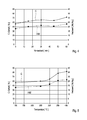
- the composition of the carbon-enriched solid product depends on the process parameters, in particular the residence time and the reaction temperature.
- This dependence is in the FIGS. 4 and 5 graphically represented, wherein Fig. 4 the dependence on the residence time and Fig. 5 illustrates the dependence on the reaction temperature.
- Fig. 4 can be seen increases, starting from a residence time of about 60 min (for example at a given temperature of eg 300 ° C) both the carbon content (graph C) and the calorific value (graph HW) of the carbon-enriched solid product.
- graph C the carbon content
- graph HW the calorific value
- Fig. 4 it can be seen that even with such low residence times, such as only 30 minutes, in the reactor system 10 according to the invention, a noticeable increase in calorific value HW and carbon content C of the carbon-enriched solid product can be achieved.
Landscapes
- Chemical & Material Sciences (AREA)
- Engineering & Computer Science (AREA)
- Oil, Petroleum & Natural Gas (AREA)
- Materials Engineering (AREA)
- Organic Chemistry (AREA)
- Combustion & Propulsion (AREA)
- Processing Of Solid Wastes (AREA)
- Carbon And Carbon Compounds (AREA)
- Physical Or Chemical Processes And Apparatus (AREA)
Priority Applications (1)
| Application Number | Priority Date | Filing Date | Title |
|---|---|---|---|
| PL11167830T PL2390301T3 (pl) | 2010-05-31 | 2011-05-27 | Instalacja reaktorowa oraz sposób wytwarzania wzbogaconego w węgiel produktu stałego za pomocą zwiększania zawartości tlenu |
Applications Claiming Priority (1)
| Application Number | Priority Date | Filing Date | Title |
|---|---|---|---|
| DE102010017175A DE102010017175A1 (de) | 2010-05-31 | 2010-05-31 | Reaktoranlage und Verfahren zur Erzeugung eines kohlenstoffangereicherten Feststoffprodukts mittels Erhöhung des Kohlenstoffgehalts |
Publications (3)
| Publication Number | Publication Date |
|---|---|
| EP2390301A2 true EP2390301A2 (fr) | 2011-11-30 |
| EP2390301A3 EP2390301A3 (fr) | 2013-03-27 |
| EP2390301B1 EP2390301B1 (fr) | 2016-04-20 |
Family
ID=44117990
Family Applications (1)
| Application Number | Title | Priority Date | Filing Date |
|---|---|---|---|
| EP11167830.6A Active EP2390301B1 (fr) | 2010-05-31 | 2011-05-27 | Installation de réacteur et procédé de production d'un produit de matière solide enrichi en carbone à l'aide d'une augmentation de la teneur en carbone |
Country Status (5)
| Country | Link |
|---|---|
| EP (1) | EP2390301B1 (fr) |
| DE (1) | DE102010017175A1 (fr) |
| DK (1) | DK2390301T3 (fr) |
| ES (1) | ES2572384T3 (fr) |
| PL (1) | PL2390301T3 (fr) |
Cited By (7)
| Publication number | Priority date | Publication date | Assignee | Title |
|---|---|---|---|---|
| DE102014103346A1 (de) * | 2014-03-12 | 2015-09-17 | Ava-Co2 Schweiz Ag | Verfahren und Vorrichtung zur Durchführung einer hydrothermalen Karbonisierungsreaktion und Verwendung eines Sensors oder Analysegeräts hierfür |
| EP2952559A1 (fr) | 2014-06-05 | 2015-12-09 | EnBW Energie Baden-Württemberg AG | Procédé de traitement d'une masse humide, à faible pouvoir calorifique |
| EP2933314A4 (fr) * | 2012-12-14 | 2016-08-10 | Mitsubishi Heavy Ind Ltd | Dispositif de carbonisation du charbon |
| CN107140683A (zh) * | 2017-07-21 | 2017-09-08 | 华北理工大学 | 基于水热法制备纳米硫化铅的系统 |
| CN110066666A (zh) * | 2018-01-23 | 2019-07-30 | 埃瓦克有限公司 | 用于处理有机废弃物的方法和系统 |
| CN118421345A (zh) * | 2023-02-02 | 2024-08-02 | 中国石油化工股份有限公司 | 生物质热解重整反应器控制方法、装置、设备和存储介质 |
| CN118421345B (en) * | 2023-02-02 | 2026-05-05 | 中国石油化工股份有限公司 | Control method, device, equipment and storage medium for biomass pyrolysis reforming reactor |
Families Citing this family (4)
| Publication number | Priority date | Publication date | Assignee | Title |
|---|---|---|---|---|
| DE102016115700A1 (de) | 2016-08-24 | 2018-03-01 | Fraunhofer-Gesellschaft zur Förderung der angewandten Forschung e.V. | Verfahren zur Veredlung von festen fossilen Brennstoffen mittels eines Pyrolysereaktors |
| CN109404718B (zh) * | 2018-12-13 | 2023-12-19 | 国能龙源环保有限公司 | 减少油品储罐VOCs排放量与密封氮气消耗量的系统及方法 |
| CN109709122B (zh) * | 2019-01-11 | 2021-02-05 | 中国人民解放军国防科技大学 | 一种高温燃气中凝相燃烧产物的收集试验装置 |
| CN112080295B (zh) * | 2020-06-12 | 2021-09-14 | 广州环渝能源科技有限公司 | 一种密封出炭方法 |
Citations (2)
| Publication number | Priority date | Publication date | Assignee | Title |
|---|---|---|---|---|
| CA639022A (en) | 1962-03-27 | Lukens Steel Company | Submerged arc weld iron base composition | |
| DE202008012419U1 (de) | 2008-09-18 | 2008-11-20 | Agrokraft Gmbh | Vorrichtung zur Behandlung von Biomasse |
Family Cites Families (4)
| Publication number | Priority date | Publication date | Assignee | Title |
|---|---|---|---|---|
| US5780518A (en) * | 1993-12-09 | 1998-07-14 | Science-Technical And Product-Innovative Center "Tokema" | Processing waste rubber by steam pyrolysis |
| CN1358221A (zh) * | 2000-01-14 | 2002-07-10 | 冈本良一 | 废物的干馏减容装置 |
| JP2002194362A (ja) * | 2000-12-27 | 2002-07-10 | Kogi Corp | 過熱水蒸気による炭化方法 |
| US8436120B2 (en) | 2007-11-20 | 2013-05-07 | Jan Piskorz | Method of producing hodge carbonyls and oligomeric lignin |
-
2010
- 2010-05-31 DE DE102010017175A patent/DE102010017175A1/de not_active Withdrawn
-
2011
- 2011-05-27 DK DK11167830.6T patent/DK2390301T3/en active
- 2011-05-27 PL PL11167830T patent/PL2390301T3/pl unknown
- 2011-05-27 ES ES11167830T patent/ES2572384T3/es active Active
- 2011-05-27 EP EP11167830.6A patent/EP2390301B1/fr active Active
Patent Citations (2)
| Publication number | Priority date | Publication date | Assignee | Title |
|---|---|---|---|---|
| CA639022A (en) | 1962-03-27 | Lukens Steel Company | Submerged arc weld iron base composition | |
| DE202008012419U1 (de) | 2008-09-18 | 2008-11-20 | Agrokraft Gmbh | Vorrichtung zur Behandlung von Biomasse |
Cited By (12)
| Publication number | Priority date | Publication date | Assignee | Title |
|---|---|---|---|---|
| EP2933314A4 (fr) * | 2012-12-14 | 2016-08-10 | Mitsubishi Heavy Ind Ltd | Dispositif de carbonisation du charbon |
| US9982196B2 (en) | 2012-12-14 | 2018-05-29 | Mitsubishi Heavy Industries, Ltd. | Device for destructive distillation of coal |
| DE102014103346A1 (de) * | 2014-03-12 | 2015-09-17 | Ava-Co2 Schweiz Ag | Verfahren und Vorrichtung zur Durchführung einer hydrothermalen Karbonisierungsreaktion und Verwendung eines Sensors oder Analysegeräts hierfür |
| EP2952559A1 (fr) | 2014-06-05 | 2015-12-09 | EnBW Energie Baden-Württemberg AG | Procédé de traitement d'une masse humide, à faible pouvoir calorifique |
| DE102014107969A1 (de) | 2014-06-05 | 2015-12-17 | EnBW Energie Baden-Württemberg AG | Verfahren zur Behandlung einer feuchten, heizwertarmen Masse |
| CN107140683A (zh) * | 2017-07-21 | 2017-09-08 | 华北理工大学 | 基于水热法制备纳米硫化铅的系统 |
| CN107140683B (zh) * | 2017-07-21 | 2023-10-24 | 华北理工大学 | 基于水热法制备纳米硫化铅的系统 |
| CN110066666A (zh) * | 2018-01-23 | 2019-07-30 | 埃瓦克有限公司 | 用于处理有机废弃物的方法和系统 |
| US11267743B2 (en) | 2018-01-23 | 2022-03-08 | Evac Oy | Method and system for treatment of organic waste |
| US11767249B2 (en) | 2018-01-23 | 2023-09-26 | Evac Oy | Method and system for treatment of organic waste |
| CN118421345A (zh) * | 2023-02-02 | 2024-08-02 | 中国石油化工股份有限公司 | 生物质热解重整反应器控制方法、装置、设备和存储介质 |
| CN118421345B (en) * | 2023-02-02 | 2026-05-05 | 中国石油化工股份有限公司 | Control method, device, equipment and storage medium for biomass pyrolysis reforming reactor |
Also Published As
| Publication number | Publication date |
|---|---|
| DE102010017175A1 (de) | 2011-12-01 |
| DK2390301T3 (en) | 2016-05-30 |
| EP2390301A3 (fr) | 2013-03-27 |
| ES2572384T3 (es) | 2016-05-31 |
| EP2390301B1 (fr) | 2016-04-20 |
| PL2390301T3 (pl) | 2016-08-31 |
Similar Documents
| Publication | Publication Date | Title |
|---|---|---|
| EP2390301B1 (fr) | Installation de réacteur et procédé de production d'un produit de matière solide enrichi en carbone à l'aide d'une augmentation de la teneur en carbone | |
| DE68907052T4 (de) | Verfahren und vorrichtung zur veredelung von organischem material. | |
| DE102007012112B3 (de) | Vorrichtung und Verfahren zur hydrothermalen Karbonisierung von Biomasse | |
| CH720670A2 (de) | Gerät zur thermischen Karbonisierung von kommunalem Schlamm | |
| EP1934306B1 (fr) | Procede de fabrication et de preparation de produits de pyrolyse rapide a partir de biomasse pour une gazeification sous pression a lit entraine | |
| EP3094704B1 (fr) | Procédé de production de gaz pyrolytique ou d'huile pyrolytique à partir de matériaux de départ biogènes | |
| EP3132004B1 (fr) | Système et procédé de traitement thermo-catalytique d'une matière et huile de pyrolyse fabriqué au moyen de ceux-ci | |
| DE19681320C2 (de) | Verfahren zur überkritischen katalytischen Vergasung von nasser Biomasse | |
| EP2598605A2 (fr) | Installation et procédé de production de carburants à partir de mélanges de biomasse et de plastique | |
| WO2010112230A1 (fr) | Procédé de carbonisation hydrothermale de matières premières renouvelables et de résidus organiques | |
| EP2762220B1 (fr) | Procédé et dispositif de récupération de gaz pauvre | |
| DE102007011763B3 (de) | Verfahren zur katalytischen Aufbereitung von Klärschlamm und Einrichtung zur Durchführung des Verfahrens | |
| EP2136170A2 (fr) | Dispositif et procédé de production de porteurs d'énergie à partir de biomasse humide | |
| EP3356299B1 (fr) | Système pour le traitement des résidues organiques avec un procédé de carbonisation hydrothermal | |
| AT519020B1 (de) | Verfahren zur Herstellung von Biokohle und Anlage hierfür | |
| EP2692425A1 (fr) | Procédé et installation de génération de carburants à partir de matières organiques au moyen d'un traitement échelonné à micro-ondes | |
| DE102006061217B3 (de) | Verfahren zur thermischen Aufbereitung von Klärschlamm und Einrichtung zur Durchführung des Verfahrens | |
| EP2082007A1 (fr) | Installation et procédé pour la production de carburants à partir de matières premières biogènes | |
| EP3178577B1 (fr) | Procédé destine à la production de cendres contenant du phosphore | |
| DE102011081802A1 (de) | Kontinuierliche, Pyrolyse-freie Dörrung von Biomassen zum Zwecke der Herstellung eines biogenen kohleähnlichen Brennstoffs | |
| EP2253693A1 (fr) | Procédé de traitement de matières résiduelles de brasseries | |
| EP2020580B1 (fr) | Procédé de préparation d'ensilage | |
| EP2952559A1 (fr) | Procédé de traitement d'une masse humide, à faible pouvoir calorifique | |
| DE102008028859A1 (de) | Selbstfahrendes Erntefahrzeug für technisch zu nutzendes Erntegut | |
| DE112013004502T5 (de) | Fester-Kohlenstoff-Produktionsvorrichtung |
Legal Events
| Date | Code | Title | Description |
|---|---|---|---|
| AK | Designated contracting states |
Kind code of ref document: A2 Designated state(s): AL AT BE BG CH CY CZ DE DK EE ES FI FR GB GR HR HU IE IS IT LI LT LU LV MC MK MT NL NO PL PT RO RS SE SI SK SM TR |
|
| AX | Request for extension of the european patent |
Extension state: BA ME |
|
| PUAI | Public reference made under article 153(3) epc to a published international application that has entered the european phase |
Free format text: ORIGINAL CODE: 0009012 |
|
| PUAL | Search report despatched |
Free format text: ORIGINAL CODE: 0009013 |
|
| AK | Designated contracting states |
Kind code of ref document: A3 Designated state(s): AL AT BE BG CH CY CZ DE DK EE ES FI FR GB GR HR HU IE IS IT LI LT LU LV MC MK MT NL NO PL PT RO RS SE SI SK SM TR |
|
| AX | Request for extension of the european patent |
Extension state: BA ME |
|
| RIC1 | Information provided on ipc code assigned before grant |
Ipc: C10B 53/02 20060101ALI20130219BHEP Ipc: C10B 57/00 20060101ALI20130219BHEP Ipc: C10B 51/00 20060101ALI20130219BHEP Ipc: C10B 57/12 20060101ALI20130219BHEP Ipc: C10B 47/44 20060101AFI20130219BHEP |
|
| 17P | Request for examination filed |
Effective date: 20130927 |
|
| RBV | Designated contracting states (corrected) |
Designated state(s): AL AT BE BG CH CY CZ DE DK EE ES FI FR GB GR HR HU IE IS IT LI LT LU LV MC MK MT NL NO PL PT RO RS SE SI SK SM TR |
|
| GRAP | Despatch of communication of intention to grant a patent |
Free format text: ORIGINAL CODE: EPIDOSNIGR1 |
|
| INTG | Intention to grant announced |
Effective date: 20151218 |
|
| GRAS | Grant fee paid |
Free format text: ORIGINAL CODE: EPIDOSNIGR3 |
|
| GRAA | (expected) grant |
Free format text: ORIGINAL CODE: 0009210 |
|
| AK | Designated contracting states |
Kind code of ref document: B1 Designated state(s): AL AT BE BG CH CY CZ DE DK EE ES FI FR GB GR HR HU IE IS IT LI LT LU LV MC MK MT NL NO PL PT RO RS SE SI SK SM TR |
|
| REG | Reference to a national code |
Ref country code: GB Ref legal event code: FG4D Free format text: NOT ENGLISH |
|
| REG | Reference to a national code |
Ref country code: CH Ref legal event code: EP |
|
| REG | Reference to a national code |
Ref country code: AT Ref legal event code: REF Ref document number: 792463 Country of ref document: AT Kind code of ref document: T Effective date: 20160515 |
|
| REG | Reference to a national code |
Ref country code: IE Ref legal event code: FG4D Free format text: LANGUAGE OF EP DOCUMENT: GERMAN |
|
| REG | Reference to a national code |
Ref country code: PT Ref legal event code: SC4A Free format text: AVAILABILITY OF NATIONAL TRANSLATION Effective date: 20160517 |
|
| REG | Reference to a national code |
Ref country code: FR Ref legal event code: PLFP Year of fee payment: 6 |
|
| REG | Reference to a national code |
Ref country code: DK Ref legal event code: T3 Effective date: 20160526 |
|
| REG | Reference to a national code |
Ref country code: ES Ref legal event code: FG2A Ref document number: 2572384 Country of ref document: ES Kind code of ref document: T3 Effective date: 20160531 |
|
| REG | Reference to a national code |
Ref country code: NL Ref legal event code: FP |
|
| REG | Reference to a national code |
Ref country code: DE Ref legal event code: R096 Ref document number: 502011009490 Country of ref document: DE |
|
| REG | Reference to a national code |
Ref country code: SE Ref legal event code: TRGR |
|
| REG | Reference to a national code |
Ref country code: NO Ref legal event code: T2 Effective date: 20160420 |
|
| REG | Reference to a national code |
Ref country code: SK Ref legal event code: T3 Ref document number: E 21068 Country of ref document: SK |
|
| PG25 | Lapsed in a contracting state [announced via postgrant information from national office to epo] |
Ref country code: GR Free format text: LAPSE BECAUSE OF FAILURE TO SUBMIT A TRANSLATION OF THE DESCRIPTION OR TO PAY THE FEE WITHIN THE PRESCRIBED TIME-LIMIT Effective date: 20160721 Ref country code: LV Free format text: LAPSE BECAUSE OF FAILURE TO SUBMIT A TRANSLATION OF THE DESCRIPTION OR TO PAY THE FEE WITHIN THE PRESCRIBED TIME-LIMIT Effective date: 20160420 Ref country code: HR Free format text: LAPSE BECAUSE OF FAILURE TO SUBMIT A TRANSLATION OF THE DESCRIPTION OR TO PAY THE FEE WITHIN THE PRESCRIBED TIME-LIMIT Effective date: 20160420 Ref country code: RS Free format text: LAPSE BECAUSE OF FAILURE TO SUBMIT A TRANSLATION OF THE DESCRIPTION OR TO PAY THE FEE WITHIN THE PRESCRIBED TIME-LIMIT Effective date: 20160420 |
|
| REG | Reference to a national code |
Ref country code: DE Ref legal event code: R097 Ref document number: 502011009490 Country of ref document: DE |
|
| PG25 | Lapsed in a contracting state [announced via postgrant information from national office to epo] |
Ref country code: MC Free format text: LAPSE BECAUSE OF FAILURE TO SUBMIT A TRANSLATION OF THE DESCRIPTION OR TO PAY THE FEE WITHIN THE PRESCRIBED TIME-LIMIT Effective date: 20160420 Ref country code: RO Free format text: LAPSE BECAUSE OF FAILURE TO SUBMIT A TRANSLATION OF THE DESCRIPTION OR TO PAY THE FEE WITHIN THE PRESCRIBED TIME-LIMIT Effective date: 20160420 Ref country code: EE Free format text: LAPSE BECAUSE OF FAILURE TO SUBMIT A TRANSLATION OF THE DESCRIPTION OR TO PAY THE FEE WITHIN THE PRESCRIBED TIME-LIMIT Effective date: 20160420 |
|
| PLBE | No opposition filed within time limit |
Free format text: ORIGINAL CODE: 0009261 |
|
| STAA | Information on the status of an ep patent application or granted ep patent |
Free format text: STATUS: NO OPPOSITION FILED WITHIN TIME LIMIT |
|
| PG25 | Lapsed in a contracting state [announced via postgrant information from national office to epo] |
Ref country code: SM Free format text: LAPSE BECAUSE OF FAILURE TO SUBMIT A TRANSLATION OF THE DESCRIPTION OR TO PAY THE FEE WITHIN THE PRESCRIBED TIME-LIMIT Effective date: 20160420 |
|
| 26N | No opposition filed |
Effective date: 20170123 |
|
| REG | Reference to a national code |
Ref country code: FR Ref legal event code: PLFP Year of fee payment: 7 |
|
| PG25 | Lapsed in a contracting state [announced via postgrant information from national office to epo] |
Ref country code: SI Free format text: LAPSE BECAUSE OF FAILURE TO SUBMIT A TRANSLATION OF THE DESCRIPTION OR TO PAY THE FEE WITHIN THE PRESCRIBED TIME-LIMIT Effective date: 20160420 |
|
| REG | Reference to a national code |
Ref country code: FR Ref legal event code: PLFP Year of fee payment: 8 |
|
| PG25 | Lapsed in a contracting state [announced via postgrant information from national office to epo] |
Ref country code: CY Free format text: LAPSE BECAUSE OF FAILURE TO SUBMIT A TRANSLATION OF THE DESCRIPTION OR TO PAY THE FEE WITHIN THE PRESCRIBED TIME-LIMIT Effective date: 20160420 Ref country code: HU Free format text: LAPSE BECAUSE OF FAILURE TO SUBMIT A TRANSLATION OF THE DESCRIPTION OR TO PAY THE FEE WITHIN THE PRESCRIBED TIME-LIMIT; INVALID AB INITIO Effective date: 20110527 |
|
| PG25 | Lapsed in a contracting state [announced via postgrant information from national office to epo] |
Ref country code: MT Free format text: LAPSE BECAUSE OF FAILURE TO SUBMIT A TRANSLATION OF THE DESCRIPTION OR TO PAY THE FEE WITHIN THE PRESCRIBED TIME-LIMIT Effective date: 20160420 Ref country code: MK Free format text: LAPSE BECAUSE OF FAILURE TO SUBMIT A TRANSLATION OF THE DESCRIPTION OR TO PAY THE FEE WITHIN THE PRESCRIBED TIME-LIMIT Effective date: 20160420 Ref country code: IS Free format text: LAPSE BECAUSE OF FAILURE TO SUBMIT A TRANSLATION OF THE DESCRIPTION OR TO PAY THE FEE WITHIN THE PRESCRIBED TIME-LIMIT Effective date: 20160420 |
|
| PG25 | Lapsed in a contracting state [announced via postgrant information from national office to epo] |
Ref country code: BG Free format text: LAPSE BECAUSE OF FAILURE TO SUBMIT A TRANSLATION OF THE DESCRIPTION OR TO PAY THE FEE WITHIN THE PRESCRIBED TIME-LIMIT Effective date: 20160420 |
|
| PG25 | Lapsed in a contracting state [announced via postgrant information from national office to epo] |
Ref country code: AL Free format text: LAPSE BECAUSE OF FAILURE TO SUBMIT A TRANSLATION OF THE DESCRIPTION OR TO PAY THE FEE WITHIN THE PRESCRIBED TIME-LIMIT Effective date: 20160420 |
|
| P01 | Opt-out of the competence of the unified patent court (upc) registered |
Effective date: 20230816 |
|
| PGFP | Annual fee paid to national office [announced via postgrant information from national office to epo] |
Ref country code: SE Payment date: 20250311 Year of fee payment: 15 |
|
| PGFP | Annual fee paid to national office [announced via postgrant information from national office to epo] |
Ref country code: NL Payment date: 20250526 Year of fee payment: 15 |
|
| PGFP | Annual fee paid to national office [announced via postgrant information from national office to epo] |
Ref country code: FI Payment date: 20250526 Year of fee payment: 15 |
|
| PGFP | Annual fee paid to national office [announced via postgrant information from national office to epo] |
Ref country code: PL Payment date: 20250507 Year of fee payment: 15 Ref country code: DE Payment date: 20250528 Year of fee payment: 15 |
|
| PGFP | Annual fee paid to national office [announced via postgrant information from national office to epo] |
Ref country code: GB Payment date: 20250520 Year of fee payment: 15 Ref country code: ES Payment date: 20250611 Year of fee payment: 15 Ref country code: DK Payment date: 20250526 Year of fee payment: 15 |
|
| PGFP | Annual fee paid to national office [announced via postgrant information from national office to epo] |
Ref country code: LT Payment date: 20250507 Year of fee payment: 15 |
|
| PGFP | Annual fee paid to national office [announced via postgrant information from national office to epo] |
Ref country code: NO Payment date: 20250520 Year of fee payment: 15 |
|
| PGFP | Annual fee paid to national office [announced via postgrant information from national office to epo] |
Ref country code: LU Payment date: 20250526 Year of fee payment: 15 Ref country code: BE Payment date: 20250526 Year of fee payment: 15 Ref country code: IT Payment date: 20250520 Year of fee payment: 15 |
|
| PGFP | Annual fee paid to national office [announced via postgrant information from national office to epo] |
Ref country code: PT Payment date: 20250415 Year of fee payment: 15 |
|
| PGFP | Annual fee paid to national office [announced via postgrant information from national office to epo] |
Ref country code: FR Payment date: 20250526 Year of fee payment: 15 |
|
| PGFP | Annual fee paid to national office [announced via postgrant information from national office to epo] |
Ref country code: CH Payment date: 20250601 Year of fee payment: 15 |
|
| PGFP | Annual fee paid to national office [announced via postgrant information from national office to epo] |
Ref country code: AT Payment date: 20250520 Year of fee payment: 15 |
|
| PGFP | Annual fee paid to national office [announced via postgrant information from national office to epo] |
Ref country code: TR Payment date: 20250506 Year of fee payment: 15 Ref country code: SK Payment date: 20250509 Year of fee payment: 15 |
|
| PGFP | Annual fee paid to national office [announced via postgrant information from national office to epo] |
Ref country code: CZ Payment date: 20250513 Year of fee payment: 15 |
|
| PGFP | Annual fee paid to national office [announced via postgrant information from national office to epo] |
Ref country code: IE Payment date: 20250520 Year of fee payment: 15 |