EP2390429A2 - Befestigungsvorrichtung insbesondere für wandhängende Sanitärobjekte - Google Patents
Befestigungsvorrichtung insbesondere für wandhängende Sanitärobjekte Download PDFInfo
- Publication number
- EP2390429A2 EP2390429A2 EP11401504A EP11401504A EP2390429A2 EP 2390429 A2 EP2390429 A2 EP 2390429A2 EP 11401504 A EP11401504 A EP 11401504A EP 11401504 A EP11401504 A EP 11401504A EP 2390429 A2 EP2390429 A2 EP 2390429A2
- Authority
- EP
- European Patent Office
- Prior art keywords
- screw
- wall
- adapter element
- head
- fastening device
- Prior art date
- Legal status (The legal status is an assumption and is not a legal conclusion. Google has not performed a legal analysis and makes no representation as to the accuracy of the status listed.)
- Granted
Links
Images

Classifications
-
- E—FIXED CONSTRUCTIONS
- E03—WATER SUPPLY; SEWERAGE
- E03C—DOMESTIC PLUMBING INSTALLATIONS FOR FRESH WATER OR WASTE WATER; SINKS
- E03C1/00—Domestic plumbing installations for fresh water or waste water; Sinks
- E03C1/12—Plumbing installations for waste water; Basins or fountains connected thereto; Sinks
- E03C1/32—Holders or supports for basins
- E03C1/322—Holders or supports for basins connected to the wall only
-
- E—FIXED CONSTRUCTIONS
- E03—WATER SUPPLY; SEWERAGE
- E03D—WATER-CLOSETS OR URINALS WITH FLUSHING DEVICES; FLUSHING VALVES THEREFOR
- E03D11/00—Other component parts of water-closets, e.g. noise-reducing means in the flushing system, flushing pipes mounted in the bowl, seals for the bowl outlet, devices preventing overflow of the bowl contents; devices forming a water seal in the bowl after flushing, devices eliminating obstructions in the bowl outlet or preventing backflow of water and excrements from the waterpipe
- E03D11/13—Parts or details of bowls; Special adaptations of pipe joints or couplings for use with bowls, e.g. provisions in bowl construction preventing backflow of waste-water from the bowl in the flushing pipe or cistern, provisions for a secondary flushing, for noise-reducing
- E03D11/14—Means for connecting the bowl to the wall, e.g. to a wall outlet
-
- F—MECHANICAL ENGINEERING; LIGHTING; HEATING; WEAPONS; BLASTING
- F16—ENGINEERING ELEMENTS AND UNITS; GENERAL MEASURES FOR PRODUCING AND MAINTAINING EFFECTIVE FUNCTIONING OF MACHINES OR INSTALLATIONS; THERMAL INSULATION IN GENERAL
- F16B—DEVICES FOR FASTENING OR SECURING CONSTRUCTIONAL ELEMENTS OR MACHINE PARTS TOGETHER, e.g. NAILS, BOLTS, CIRCLIPS, CLAMPS, CLIPS OR WEDGES; JOINTS OR JOINTING
- F16B35/00—Screw-bolts; Stay-bolts; Screw-threaded studs; Screws; Set screws
- F16B35/04—Screw-bolts; Stay-bolts; Screw-threaded studs; Screws; Set screws with specially-shaped head or shaft in order to fix the bolt on or in an object
- F16B35/06—Specially-shaped heads
-
- F—MECHANICAL ENGINEERING; LIGHTING; HEATING; WEAPONS; BLASTING
- F16—ENGINEERING ELEMENTS AND UNITS; GENERAL MEASURES FOR PRODUCING AND MAINTAINING EFFECTIVE FUNCTIONING OF MACHINES OR INSTALLATIONS; THERMAL INSULATION IN GENERAL
- F16B—DEVICES FOR FASTENING OR SECURING CONSTRUCTIONAL ELEMENTS OR MACHINE PARTS TOGETHER, e.g. NAILS, BOLTS, CIRCLIPS, CLAMPS, CLIPS OR WEDGES; JOINTS OR JOINTING
- F16B5/00—Joining sheets or plates, e.g. panels, to one another or to strips or bars parallel to them
- F16B5/02—Joining sheets or plates, e.g. panels, to one another or to strips or bars parallel to them by means of fastening members using screw-thread
- F16B5/025—Joining sheets or plates, e.g. panels, to one another or to strips or bars parallel to them by means of fastening members using screw-thread specially designed to compensate for misalignement or to eliminate unwanted play
-
- F—MECHANICAL ENGINEERING; LIGHTING; HEATING; WEAPONS; BLASTING
- F16—ENGINEERING ELEMENTS AND UNITS; GENERAL MEASURES FOR PRODUCING AND MAINTAINING EFFECTIVE FUNCTIONING OF MACHINES OR INSTALLATIONS; THERMAL INSULATION IN GENERAL
- F16B—DEVICES FOR FASTENING OR SECURING CONSTRUCTIONAL ELEMENTS OR MACHINE PARTS TOGETHER, e.g. NAILS, BOLTS, CIRCLIPS, CLAMPS, CLIPS OR WEDGES; JOINTS OR JOINTING
- F16B33/00—Features common to bolt and nut
- F16B33/002—Means for preventing rotation of screw-threaded elements
Definitions
- the invention relates to a fastening device, in particular for wall-hung sanitary objects having the features of the preamble of claim 1.
- WO 2009/074301 is a fastening device for a sanitary object, in particular a toilet bowl, known.
- the known fastening device has a hook-shaped body, which comes with a contact surface on a wall to the plant and can be fastened to the wall.
- On a bearing surface perpendicular to the wall the sanitary object can be supported.
- the sanitary object is held by means of a screw which extends through a receiving opening of the sanitary object and into the basic body.
- a carriage On the main body, a carriage is guided linearly with a nut, wherein the guide is arranged obliquely to the contact surface. The screw engages in the nut. By tightening the nut of the carriage is moved along its guide and thereby generates a force that pulls the sanitary object both to the main body and the wall.
- a cage with a cage nut is attached.
- This cage nut is used to attach another part of the sanitary object, in particular the attachment of a hinge of a pelvic seat.
- the screw thus receives an additional attachment function.
- the cage and the cage nut together serve as an adapter element for attaching another part of the sanitary object.
- the cage sits on a sleeve, which in turn rests on the body. This causes the cage is secured only by friction against rotation. As a result, there is a risk that it comes to a co-rotation of the cage when screwing or unscrewing the screw of a hinge in the cage nut. In particular, when dismantling this can have the consequence that a non-destructive disassembly is impossible.
- the invention is therefore based on the object to improve the assembly and disassembly properties of such a fastening device.
- the fastening device has a base body which has a contact surface for abutment against a wall.
- the main body serves to fasten an object, in particular a sanitary object such as a toilet bowl.
- the fastening device has a carriage, which is guided obliquely to the contact surface.
- the guide need not be linear, but it may for example also be arcuate, which has an effect on the resulting from the tightening torque fastening forces in the direction and size.
- the carriage has an internal thread element, which is in particular rotationally fixedly connected to the carriage.
- the female thread member may also be integral with the carriage.
- a female thread is preformed, but it can also be provided a portion in which during the assembly of the object on a wall only the internal thread is formed.
- a bore can be provided with inwardly standing longitudinal ribs.
- the fastening device has a screw for passage through a receiving opening of the object, which can be screwed into the internal thread element.
- an adapter element is arranged with a receiving thread.
- the receiving thread can be an internal or external thread. It serves to attach another part, in particular the attachment of a hinge for a pelvic seat and lid.
- the adapter element is tension-proof connected to the screw, so that, for example, a hinge with bias against the basin can be mounted.
- the receiving thread is radially displaceable to the screw, which in particular a tolerance compensation is possible when, for example, a pelvic seat with two hinges is attached to the screws of two inventive fastening devices and their position does not correspond exactly with the distance of the hinges.
- the displaceability of the receiving thread can be achieved on the one hand by a displaceability of the adapter element to the screw head and on the other hand by a displaceability within the adapter element.
- the adapter element is positively connected rotationally fixed to the head. Compared to the prior art, this has the great advantage that it does not regularly come to a rotation of the adapter element to the screw.
- the object When mounting, for example, a hinge on the fastening device, assuming the same direction thread, the object tends to be pulled even more against the wall.
- the disassembly of the hinge could lead in the worst case, that the sled loosens, but never to that the adapter element rotates and a nondestructive disassembly is impossible.
- the torques can be adjusted so that the release, for example, a hinge screw never leads to co-rotation of the screw of the fastening device.
- the head preferably has one, in particular two, secant-like grooves. This allows a simple production starting from a standard screw and also allows in addition to the positive rotary connection and a positive tension connection.
- the adapter in which it has at least one claw, which engages in the at least one groove and forms a snap connection with the screw, preferably corresponds with a head designed in this way. This prevents in a simple manner, in particular during pre-assembly, during transport and during assembly of the object on site, that the connection of adapter element and screw is unintentionally released.
- FIG. 1 shows the fastening device 1 according to the invention for fixing an object 2, here a toilet bowl made of ceramic, on a wall 3.
- the fastening device 1 has an angular base body 4 made of plastic, the first leg 5 outside a contact surface 6 for abutment against the wall 3 forms.
- a mounting hole 7 is arranged, through which a threaded rod 8 grouted in the wall 3 protrudes.
- the base body 4 is tensioned with the contact surface 6 against the wall 3.
- a second leg 10 of the main body 4 forms a support for the object 2.
- the upper side of the second leg 10 serves as a bearing surface 11 on which the object comes to rest with an upper inner wall 12.
- the angle-shaped basic body 4 has, inter alia, reinforcing side walls 13.
- the side walls 13 are perpendicular to both legs 5, 10, wherein only one of the side walls 13 is shown, while the other side wall 13 is arranged symmetrically in front of the cutting plane.
- a guide surface 14 is arranged on the side wall 13, which is inclined at an angle W of approximately 50 ° to the wall 3 or the contact surface 6.
- the guide surfaces 14 form a guide 15 of an arranged between the side walls 13, approximately cuboid carriage 16 made of plastic, which has a corresponding contour (not shown).
- cylindrical internal thread member 17 is disposed of metal with an internal thread 18 having through hole 19 and a central constriction 20 on the outside. In the manufacture of the carriage 16, the internal thread member 17 is molded as an insert and therefore finds optimal support.
- the object has a fastening portion 21 which projects up to the wall 3 and is supported on the support surface 11.
- the attachment portion 21 is penetrated by a receiving opening 22.
- the receiving opening 22 tapers step-like manner relative to the main body 4, thereby forming a shoulder 23 against which the head 24 of a screw 25 made of steel is supported.
- the screw 25 is inserted in the mounting of the object 2 on the wall 3 after placing the object 2 on the base body 4 in the receiving opening 22. It protrudes through the receiving opening 22 through into the base body 4 and is screwed into the female thread member 17.
- the support on the shoulder 23 is not direct, since the contact of steel on ceramic could lead to cracks in the ceramic.
- the head 24 is therefore supported by a washer 26 and a hat-shaped sleeve 27 on the shoulder 23 from. At the same time, the sleeve 27 also prevents direct radial contact of the screw 25 in the receiving opening 22.
- the head 24 of the screw 25 has a cylindrical basic shape with a relatively small hexagon socket 29 as a tool approach, wherein instead of the hexagon socket 29, a star-shaped tool approach, cross recess or the like are used could.
- the side 24 in the head 24, two parallel, secant extending grooves 30 are introduced. In the grooves 30 respectively claws 31 engage an adapter element 32 made of plastic.
- the adapter element 32 has a substantially cylindrical outer shape and is centrally penetrated by a through hole 33.
- the upper half of the through hole 33 corresponds in diameter substantially to the shank of the screw 25 and has an encapsulated embedded fastening nut 34, which tapers the through-hole 33 and gives the adapter element 32 a receiving thread 35.
- this widens bell-shaped and closes with the claws 31 from.
- the through hole 33 also widens radially in this area to one side, so that the adapter element 32 is laterally open. As a result, the adapter element 32 can be pushed laterally onto the head 24 of the screw 25 during the pre-assembly of the fastening device 1.
- the claws 31 comprise the head 24 in the area of the grooves 30 in a U-shape.
- the claws 31 each have mutually facing cranks 36. As a result, a bottleneck 37 is created, which causes the adapter element 32 can be pushed with little effort on the head 24 and released from it again.
- the claws 31 thus form with the grooves 30 of the screw 25 a snap connection 38.
- the claws 31 are otherwise dimensioned so in their clearance and in the position of the cranks 36 that the adapter member 32 with radial play in all directions held on the screw 25 is.
- a positive tensile strength and rotationally fixed connection At the same time created by the engagement of the claws 31 in the grooves 30 a positive tensile strength and rotationally fixed connection.
- the screw 25 is tightened with an external hex key (not shown).
- the Befest Trentsmuter 34 is so large and the hexagon socket 29 dimensioned so small that the Allen key can be passed through the through hole 33 of the adapter member 32 through into the hexagon socket 29.
- a threaded bolt 39 can be screwed into the fastening nut 34.
- the threaded bolt 39 has a flange-like extension 40, which covers the receiving opening 22.
- a hinge of a pelvic seat (not shown) could be attached. Due to the rotationally fixed connection of mounting nut 34, adapter element 32 and Screw 25, it can not come to an unintentional spinning of the components during assembly. At the same time a tolerance compensation can take place by the game between adapter element 32 and screw 25, for example, if the distance between two hinges of a pelvic seat does not match exactly with the position of the two corresponding fastening devices 1.
Landscapes
- Engineering & Computer Science (AREA)
- General Engineering & Computer Science (AREA)
- Mechanical Engineering (AREA)
- Health & Medical Sciences (AREA)
- Life Sciences & Earth Sciences (AREA)
- Hydrology & Water Resources (AREA)
- Public Health (AREA)
- Water Supply & Treatment (AREA)
- Environmental & Geological Engineering (AREA)
- Toilet Supplies (AREA)
- Supports Or Holders For Household Use (AREA)
- Dowels (AREA)
Abstract
Description
- Die Erfindung betrifft eine Befestigungsvorrichtung insbesondere für wandhängende Sanitärobjekte mit den Merkmalen des Oberbegriffs des Anspruchs 1.
- Aus der Druckschrift
WO 2009/074301 ist eine Befestigungsvorrichtung für ein Sanitärobjekt, im Speziellen ein Toilettenbecken, bekannt. Die bekannte Befestigungsvorrichtung weist einen hakenförmigen Grundkörper auf, der mit einer Anlagefläche an einer Wand zur Anlage kommt und an der Wand befestigbar ist. Auf einer senkrecht zur Wand stehenden Auflagerfläche kann das Sanitärobjekt abgestützt werden. Gehalten wird das Sanitärobjekt mittels einer Schraube, die durch eine Aufnahmeöffnung des Sanitärobjekts hindurch bis in den Grundkörper reicht. Am Grundkörper ist ein Schlitten mit einer Mutter linear geführt, wobei die Führung schräg zur Anlagefläche angeordnet ist. Die Schraube greift in die Mutter. Durch Anziehen der Mutter wird der Schlitten entlang seiner Führung verschoben und hierdurch eine Kraft erzeugt, die das Sanitärobjekt sowohl zum Grundkörper als auch zur Wand zieht. - Am Kopf der Schraube ist ein Käfig mit einer Käfigmutter angebracht. Diese Käfigmutter dient der Befestigung eines weiteren Teils am Sanitärobjekt, insbesondere der Befestigung eines Scharniers eines Beckensitzes. Die Schraube erhält so eine zusätzliche Befestigungsfunktion. Anders ausgedrückt dienen der Käfig und die Käfigmutter zusammen als Adapterelement zur Befestigung eines weiteren Teils am Sanitärobjekt. Der Käfig sitzt auf einer Hülse auf, die wiederum auf dem Grundkörper aufsitzt. Dies bewirkt, dass der Käfig nur durch Reibung gegen Verdrehen gesichert ist. Hierdurch besteht die Gefahr, dass es zu einem Mitdrehen des Käfigs beim Ein- oder Ausschrauben der Schraube eines Scharniers in die Käfigmutter kommt. Insbesondere beim Demontieren kann dies zur Folge haben, dass eine zerstörungsfreie Demontage unmöglich wird.
- Der Erfindung liegt daher die Aufgabe zu Grunde, die Montage- und Demontageeigenschaften einer derartigen Befestigungsvorrichtung zu verbessern.
- Diese Aufgabe wird erfindungsgemäß durch die Merkmale des Anspruchs 1 gelöst.
- Die erfindungsgemäße Befestigungsvorrichtung weist einen Grundkörper auf, der eine Anlagefläche zur Anlage an einer Wand aufweist. Der Grundkörper dient der Befestigung eines Objekts, insbesondere eines Sanitärobjekts wie ein Toilettenbecken. Die Befestigungsvorrichtung weist einen Schlitten auf, der schräg zur Anlagefläche geführt ist. Dabei muss die Führung nicht linear sein, sondern sie kann beispielsweise auch bogenförmig sein, was sich auf die aus dem Anzugsmoment resultierenden Befestigungskräfte in Richtung und Größe auswirkt. Der Schlitten weist ein Innengewindeelement auf, das insbesondere drehfest mit dem Schlitten verbunden ist. Das Innengewindeelement kann auch einstückig mit dem Schlitten sein. Vorzugsweise ist ein Innengewinde vorgeformt, es kann jedoch auch ein Abschnitt vorgesehen werden, in dem während der Montage des Objekts an einer Wand erst das Innengewinde geformt wird. Hierzu kann beispielsweise eine Bohrung mit nach innen stehenden Längsrippen vorgesehen werden. Weiterhin weist die Befestigungsvorrichtung eine Schraube zur Durchführung durch eine Aufnahmeöffnung des Objekts auf, die in das Innengewindeelement einschraubbar ist. Am Kopf der Schraube ist ein Adapterelement mit einem Aufnahmegewinde angeordnet. Das Aufnahmegewinde kann ein Innen- oder Außengewinde sein. Es dient der Befestigung eines weiteren Teils, insbesondere der Befestigung eines Scharniers für einen Beckensitz und -deckel. Das Adapterelement ist zugfest mit der Schraube verbunden, so dass beispielsweise ein Scharnier mit Vorspannung gegen das Becken montiert werden kann. Das Aufnahmegewinde ist radial verschieblich zur Schraube, wodurch insbesondere ein Toleranzausgleich möglich wird, wenn beispielsweise ein Beckensitz mit zwei Scharnieren an den Schrauben zweier erfindungsgemäßer Befestigungsvorrichtungen befestigt wird und deren Position nicht genau mit dem Abstand der Scharniere korrespondiert. Die Verschieblichkeit des Aufnahmegewindes kann einerseits durch eine Verschieblichkeit des Adapterelements zum Schraubenkopf und andererseits durch eine Verschieblichkeit innerhalb des Adapterelements erreicht werden. Weiterhin ist das Adapterelement formschlüssig drehfest mit dem Kopf verbunden. Gegenüber dem Stand der Technik hat dies den großen Vorteil, dass es regelmäßig nicht zu einer Verdrehung des Adapterelements zur Schraube kommt. Bei der Montage beispielsweise eines Scharniers an der Befestigungsvorrichtung wird, gleichsinnige Gewinde vorausgesetzt, das Objekt eher noch mehr an die Wand gezogen. Die Demontage des Scharniers könnte zwar im schlimmsten Fall dazu führen, dass sich der Schlitten lockert, jedoch niemals dazu, dass das Adapterelement durchdreht und eine zerstörungsfreie Demontage unmöglich wird. Insbesondere durch die Wahl eines größeren Gewindedurchmessers der Schraube als des Aufnahmegewindes können die Drehmomente so eingestellt werden, dass das Lösen beispielsweise einer Scharnierschraube niemals zum Mitdrehen der Schraube der Befestigungsvorrichtung führt.
- Zur Erstellung einer formschlüssigen, drehfesten Verbindung zwischen Adapterelement und Kopf der Schraube weist der Kopf vorzugsweise eine, insbesondere zwei sekantenartig angeordnete Nuten auf. Dies ermöglicht eine einfache Herstellung ausgehend von einer Standardschraube und ermöglicht außerdem neben der formschlüssigen Drehverbindung auch eine formschlüssige Zugverbindung.
- Mit einem derart gestalteten Kopf korrespondiert vorzugsweise der Adapter, in dem er mindestens eine Klaue aufweist, die in die mindestens eine Nut eingreift und mit der Schraube eine Schnappverbindung bildet. Dies verhindert auf einfache Weise insbesondere bei der Vormontage, beim Transport und bei der Montage des Objekts vor Ort, dass die Verbindung von Adapterelement und Schraube ungewollt gelöst wird.
- Die Erfindung wird nachfolgend anhand eines Ausführungsbeispiels erläutert. Es zeigen:
- Figur 1
- die erfindungsgemäße Befestigungseinrichtung in einem Vertikalschnitt; und
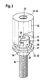
- Figur 2
- die Schraube und das Adapterelement sowie eine Unterlegscheibe und eine Hülse der Befestigungseinrichtung aus
Figur 1 in einer vergrößerten perspektivischen Darstellung. -
Figur 1 zeigt die erfindungsgemäße Befestigungsvorrichtung 1 zur Befestigung eines Objekts 2, hier eines Toilettenbeckens aus Keramik, an einer Wand 3. Die Befestigungsvorrichtung 1 weist einen winkelförmigen Grundkörper 4 aus Kunststoff auf, dessen erster Schenkel 5 außen eine Anlagefläche 6 zur Anlage an der Wand 3 bildet. Im ersten Schenkel 5 ist ein Befestigungsloch 7 angeordnet, durch den eine in der Wand 3 eingemörtelte Gewindestange 8 ragt. Mittels einer Mutter 9 ist der Grundkörper 4 mit der Anlagefläche 6 gegen die Wand 3 gespannt. Ein zweiter Schenkel 10 des Grundkörpers 4 bildet eine Stütze für das Objekt 2. Die obere Seite des zweiten Schenkels 10 dient als Auflagerfläche 11, auf der das Objekt mit einer oberen Innenwand 12 zur Anlage kommt. - Der winkelförmige Grundkörper 4 weist unter anderem zur Verstärkung Seitenwände 13 auf. Die Seitenwände 13 stehen senkrecht zu beiden Schenkeln 5, 10, wobei nur eine der Seitenwände 13 dargestellt ist, während die andere Seitenwand 13 symmetrisch vor der Schnittebene angeordnet ist. Nach innen weisend ist an der Seitenwand 13 je eine Führungsfläche 14 angeordnet, die schräg in einem Winkel W von etwa 50° zur Wand 3 bzw. zur Anlagefläche 6 steht. Die Führungsflächen 14 bilden eine Führung 15 eines zwischen den Seitenwänden 13 angeordneten, in etwa quaderförmigen Schlittens 16 aus Kunststoff, der eine korrespondierende Kontur (nicht dargestellt) aufweist. Im Schlitten 16 ist ein längliches, zylindrisches Innengewindeelement 17 aus Metall mit einem ein Innengewinde 18 aufweisenden Durchgangsloch 19 und einer mittigen Einschnürung 20 an der Außenseite angeordnet. Bei der Herstellung des Schlittens 16 wird das Innengewindeelement 17 als Einlegeteil umspritzt und findet daher optimalen Halt.
- Das Objekt weist einen Befestigungsabschnitt 21 auf, der bis zur Wand 3 ragt und sich auf der Auflagerfläche 11 abstützt. Der Befestigungsabschnitt 21 wird durch eine Aufnahmeöffnung 22 durchsetzt. Die Aufnahmeöffnung 22 verjüngt sich zum Grundkörper 4 hin stufenartig und bildet hierdurch eine Schulter 23, an der sich der Kopf 24 einer Schraube 25 aus Stahl abstützt. Die Schraube 25 wird bei der Montage des Objekts 2 an der Wand 3 nach dem Aufsetzen des Objekts 2 auf dem Grundkörper 4 in die Aufnahmeöffnung 22 gesteckt. Sie ragt durch die Aufnahmeöffnung 22 hindurch bis in den Grundkörper 4 und wird in das Innengewindeelement 17 eingeschraubt. Die Abstützung an der Schulter 23 erfolgt nicht direkt, da der Kontakt von Stahl auf Keramik zu Rissen in der Keramik führen könnte. Der Kopf 24 stützt sich daher über eine Unterlegscheibe 26 und eine hutförmige Hülse 27 auf der Schulter 23 ab. Gleichzeitig verhindert die Hülse 27 auch eine unmittelbare radiale Anlage der Schraube 25 in der Aufnahmeöffnung 22.
- Beim Anziehen der Schraube 25 wird der Schlitten 16 schräg entlang der Führung 15 gezogen. Dies bewirkt ein Heranziehen des Objekts 2 sowohl in Richtung des Grundkörpers 4 als auch in Richtung der Wand 3.
- Der Kopf 24 der Schraube 25 hat eine zylindrische Grundform mit einem relativ kleinen Innensechskant 29 als Werkzeugansatz, wobei statt dem Innensechskant 29 auch ein sternförmiger Werkzeugansatz, Kreuzschlitz oder dergleichen zum Einsatz kommen könnte. Seitlich sind in den Kopf 24 zwei parallele, sekantenartig verlaufende Nuten 30 eingebracht. In die Nuten 30 greifen jeweils Klauen 31 eines Adapterelements 32 aus Kunststoff ein. Zum besseren Verständnis sind die Schraube 25, das Adapterelement 32 sowie die Hülse 27 und die Unterlegscheibe 26 in
Figur 2 vergrößert in perspektivischer Darstellung gezeigt. Das Adapterelement 32 hat im Wesentlichen eine zylindrische Außenform und ist mittig von einer Durchgangsbohrung 33 durchsetzt. Die obere Hälfte der Durchgangsbohrung 33 entspricht dabei im Durchmesser im Wesentlichen dem Schaft der Schraube 25 und weist eine umspritzt eingebettete Befestigungsmutter 34 auf, die die Durchgangsbohrung 33 verjüngt und dem Adapterelement 32 ein Aufnahmegewinde 35 verleiht. In der unteren Hälfte der Durchgangsbohrung 33 erweitert sich diese glockenförmig und schließt mit den Klauen 31 ab. Die Durchgangsbohrung 33 erweitert sich außerdem in diesem Bereich radial zu einer Seite hin, so dass das Adapterelement 32 seitlich offen ist. Hierdurch kann das Adapterelement 32 im Rahmen der Vormontage der Befestigungsvorrichtung 1 seitlich auf den Kopf 24 der Schraube 25 aufgeschoben werden. Die Klauen 31 umfassen U-förmig den Kopf 24 im Bereich der Nuten 30. An ihren äußeren, radialen Enden weisen die Klauen 31 jeweils zueinander gewandte Kröpfungen 36 auf. Hierdurch wird eine Engstelle 37 geschaffen, die bewirkt, dass das Adapterelement 32 nur mit leichtem Kraftaufwand auf den Kopf 24 geschoben und wieder von diesem gelöst werden kann. Die Klauen 31 bilden so mit den Nuten 30 der Schraube 25 eine Schnappverbindung 38. Die Klauen 31 sind ansonsten so in ihrer lichten Weite und in der Position der Kröpfungen 36 bemessen, dass das Adapterelement 32 mit radialem Spiel in alle Richtungen an der Schraube 25 gehalten ist. Gleichzeitig entsteht durch den Eingriff der Klauen 31 in die Nuten 30 eine formschlüssig zugfeste und drehfeste Verbindung. - Wie oben beschrieben wird zum Heranziehen des Objekts 2 an die Wand 3 die Schraube 25 mit einem Außensechskantschlüssel (nicht dargestellt) angezogen. Die Befestigungsmuter 34 ist so groß und der Innensechskant 29 so klein dimensioniert, dass der Außensechskantschlüssel durch die Durchgangsbohrung 33 des Adapterelements 32 hindurch bis in den Innensechskant 29 geführt werden kann.
- Anschließend kann ein Gewindebolzen 39 in die Befestigungsmutter 34 eingeschraubt werden. Im Ausführungsbeispiel weist der Gewindebolzen 39 eine flanschartige Erweiterung 40 auf, die die Aufnahmeöffnung 22 abdeckt. Am Gewindebolzen 39 könnte beispielsweise ein Scharnier eines Beckensitzes (nicht dargestellt) befestigt werden. Durch die drehfeste Verbindung von Befestigungsmutter 34, Adapterelement 32 und Schraube 25 kann es bei der Montage nicht zu einem ungewollten Durchdrehen der Bauteile kommen. Gleichzeitig kann durch das Spiel zwischen Adapterelement 32 und Schraube 25 ein Toleranzausgleich stattfinden, wenn beispielsweise der Abstand zweier Scharniere eines Beckensitzes nicht exakt mit der Position der beiden entsprechenden Befestigungsvorrichtungen 1 übereinstimmt.
- Sollte der Gewindebolzen 39 anschließend demontiert werden müssen, so kann er aus der Befestigungsmutter 34 herausgeschraubt werden, wobei wiederum ein Mitdrehen durch die drehfesten Verbindungen ausgeschlossen ist. Dadurch, dass der Durchmesser des Gewindebolzens 39 deutlich kleiner als der der Schraube 25 ist, kommt es beim Lösen des Gewindebolzen 39 nicht zu einem Mitdrehen der Schraube 25.
-
- 1
- Befestigungsvorrichtung
- 2
- Objekt
- 3
- Wand
- 4
- Grundkörper
- 5
- erster Schenkel
- 6
- Anlagefläche
- 7
- Befestigungsloch
- 8
- Gewindestange
- 9
- Mutter
- 10
- zweiter Schenkel
- 11
- Auflagerfläche
- 12
- Innenwand
- 13
- Seitenwand
- 14
- Führungsfläche
- 15
- Führung
- 16
- Schlitten
- 17
- Innengewindeelement
- 18
- Innengewinde
- 19
- Durchgangsloch
- 20
- Einschnürung
- 21
- Befestigungsabschnitt
- 22
- Aufnahmeöffnung
- 23
- Schulter
- 24
- Kopf
- 25
- Schraube
- 26
- Unterlegscheibe
- 27
- Hülse
- 28
- Anschlag
- 29
- Innensechskant
- 30
- Nut
- 31
- Klaue
- 32
- Adapterelement
- 33
- Durchgangsbohrung
- 34
- Befestigungsmutter
- 35
- Aufnahmegewinde
- 36
- Kröpfung
- 37
- Engstelle
- 38
- Schnappverbindung
- 39
- Gewindebolzen
- 40
- Erweiterung
- W
- Winkel der Führung 15 zur Anlagefläche 6
Claims (3)
- Befestigungsvorrichtung (1), insbesondere für wandhängende Sanitärobjekte, mit- einem Grundkörper (4), der eine Anlagefläche (6) zur Anlage an einer Wand (3) aufweist, und an dem ein Objekt (2), insbesondere ein Sanitärobjekt, befestigbar ist,- einem Schlitten (16), der am Grundkörper (4) schräg zur Anlagefläche (6) geführt ist und ein Innengewindeelement (17) aufweist,- einer Schraube (25) zur Durchführung durch eine Aufnahmeöffnung (22) des Objekts (2), die in das Innengewindeelement (17) einschraubbar ist,- einem Adapterelement (32), das zugfest am Kopf (24) der Schraube (25) angeordnet ist und ein Aufnahmegewinde (35) aufweist,- wobei das Aufnahmegewinde (35) radial verschieblich zur Schraube (25) ist, dadurch gekennzeichnet, dass das Adapterelement (32) formschlüssig drehfest mit dem Kopf (24) verbunden ist.
- Befestigungsvorrichtung nach Anspruch 1, dadurch gekennzeichnet, dass der Kopf (24) mindestens eine, vorzugsweise zwei, sekantenartig angeordnete Nuten (30) aufweist.
- Befestigungsvorrichtung nach Anspruch 2, dadurch gekennzeichnet, dass das Adapterelement (32) eine Klaue (31) aufweist, die in die Nut (30) eingreift und mit der Schraube (25) eine Schnappverbindung (38) bildet.
Priority Applications (1)
| Application Number | Priority Date | Filing Date | Title |
|---|---|---|---|
| PL11401504T PL2390429T3 (pl) | 2010-05-25 | 2011-05-03 | Urządzenie mocujące w szczególności dla zawieszanych na ścianie przedmiotów sanitarnych |
Applications Claiming Priority (1)
| Application Number | Priority Date | Filing Date | Title |
|---|---|---|---|
| DE102010021384A DE102010021384A1 (de) | 2010-05-25 | 2010-05-25 | Befestigungsvorrichtung insbesondere für wandhängende Sanitärobjekte |
Publications (3)
| Publication Number | Publication Date |
|---|---|
| EP2390429A2 true EP2390429A2 (de) | 2011-11-30 |
| EP2390429A3 EP2390429A3 (de) | 2017-11-08 |
| EP2390429B1 EP2390429B1 (de) | 2019-05-08 |
Family
ID=44501574
Family Applications (1)
| Application Number | Title | Priority Date | Filing Date |
|---|---|---|---|
| EP11401504.3A Active EP2390429B1 (de) | 2010-05-25 | 2011-05-03 | Befestigungsvorrichtung insbesondere für wandhängende Sanitärobjekte |
Country Status (4)
| Country | Link |
|---|---|
| EP (1) | EP2390429B1 (de) |
| DE (1) | DE102010021384A1 (de) |
| ES (1) | ES2741155T3 (de) |
| PL (1) | PL2390429T3 (de) |
Cited By (2)
| Publication number | Priority date | Publication date | Assignee | Title |
|---|---|---|---|---|
| WO2017089009A1 (de) * | 2015-11-26 | 2017-06-01 | Villeroy & Boch Ag | Befestigungssystem für einen toilettensitz, käfig, käfigmutter, verwendung, anordnung und verfahren |
| CN108730302A (zh) * | 2017-04-19 | 2018-11-02 | 吉博力国际股份公司 | 固定系统 |
Families Citing this family (1)
| Publication number | Priority date | Publication date | Assignee | Title |
|---|---|---|---|---|
| CH720786A2 (de) * | 2023-05-16 | 2024-11-29 | Laufen Schweiz Ag | Wandbefestigung für Sanitärartikel und Sanitärartikel mit einer Wandbefestigung |
Citations (1)
| Publication number | Priority date | Publication date | Assignee | Title |
|---|---|---|---|---|
| WO2009074301A1 (de) | 2007-12-12 | 2009-06-18 | Villeroy & Boch Ag | Vorrichtung zum befestigen eines wandhängenden objektes |
Family Cites Families (1)
| Publication number | Priority date | Publication date | Assignee | Title |
|---|---|---|---|---|
| ITPD20070401A1 (it) * | 2007-12-04 | 2009-06-05 | Fischer Italia S R L Uniperson | Dispositivo di fissaggio, particolarmente per sanitari sospesi a parete |
-
2010
- 2010-05-25 DE DE102010021384A patent/DE102010021384A1/de not_active Withdrawn
-
2011
- 2011-05-03 PL PL11401504T patent/PL2390429T3/pl unknown
- 2011-05-03 EP EP11401504.3A patent/EP2390429B1/de active Active
- 2011-05-03 ES ES11401504T patent/ES2741155T3/es active Active
Patent Citations (1)
| Publication number | Priority date | Publication date | Assignee | Title |
|---|---|---|---|---|
| WO2009074301A1 (de) | 2007-12-12 | 2009-06-18 | Villeroy & Boch Ag | Vorrichtung zum befestigen eines wandhängenden objektes |
Cited By (4)
| Publication number | Priority date | Publication date | Assignee | Title |
|---|---|---|---|---|
| WO2017089009A1 (de) * | 2015-11-26 | 2017-06-01 | Villeroy & Boch Ag | Befestigungssystem für einen toilettensitz, käfig, käfigmutter, verwendung, anordnung und verfahren |
| CN108601491A (zh) * | 2015-11-26 | 2018-09-28 | 德国唯宝股份公司 | 马桶座的紧固系统、外壳、笼式螺母、应用、设备和方法 |
| CN108730302A (zh) * | 2017-04-19 | 2018-11-02 | 吉博力国际股份公司 | 固定系统 |
| CN108730302B (zh) * | 2017-04-19 | 2021-09-07 | 吉博力国际股份公司 | 固定系统 |
Also Published As
| Publication number | Publication date |
|---|---|
| EP2390429A3 (de) | 2017-11-08 |
| DE102010021384A1 (de) | 2011-12-01 |
| ES2741155T3 (es) | 2020-02-10 |
| PL2390429T3 (pl) | 2019-11-29 |
| EP2390429B1 (de) | 2019-05-08 |
Similar Documents
| Publication | Publication Date | Title |
|---|---|---|
| EP2382395B1 (de) | Vorrichtung zum ausrichten eines körpers relativ zu einer unterlage- oder anlagefläche | |
| DE102005022449A1 (de) | Abstandshalter für die Befestigung eines Gegenstandes an einem eine Dämmschicht aufweisenden Untergrund | |
| EP2390430B1 (de) | Befestigungsvorrichtung, insbesondere für wandhängende Sanitärobjekte | |
| EP0206327B1 (de) | Vorrichtung zum Verbinden von Rohren | |
| DE102014008166A1 (de) | Hochfeste Befestigungsvorrichtung | |
| DE10253888B4 (de) | Befestigungseinheit | |
| EP0908637A2 (de) | Mutter und Rohrschelle | |
| DE102012103721A1 (de) | Befestigungsvorrichtung für Sanitärkeramiken und Befestigungsanordnung | |
| EP2390429B1 (de) | Befestigungsvorrichtung insbesondere für wandhängende Sanitärobjekte | |
| DE60107712T2 (de) | Abreissbefestigungselement | |
| EP1321589B1 (de) | Befestigungsbeschlag für eine Sanitärbefestigung | |
| EP1582684B1 (de) | Schraube zur Verankerung eines mit einem Metallprofil verstärkten Kunststoffhohlprofils an einem Unterbau | |
| EP3047159B1 (de) | Profilverbinder sowie profilverbund | |
| DE20312075U1 (de) | Vorrichtung mit zwei durch eine Verbindungsschraube zusammengehaltenen Hohlprofilen sowie Werkzeug dazu | |
| AT510315B1 (de) | Anordnung zur, insbesondere distanzierten, befestigung zumindest einer dämmstoffplatte an einem gebäude | |
| EP2126378B1 (de) | Zug/kippverbindersystem | |
| EP2395160A2 (de) | Vorrichtung zum Befestigen einer Abdeckung an einem Waschtisch | |
| EP2155516B1 (de) | Querdachträger zur befestigung an längsdachträgern von transportmitteln | |
| DE102010055808A1 (de) | Befestigungsvorrichtung | |
| EP4001527A1 (de) | Wandhalter, insbesondere für ein sanitärobjekt | |
| DE202007002604U1 (de) | Profilverbinder sowie Profilverbund | |
| DE20018425U1 (de) | Schraube zur Verankerung eines Hohlprofils an einem Unterbau | |
| DE102020107563A1 (de) | Befestigungsvorrichtung für ein zu hängendes Sanitärbauteil | |
| EP2434166B1 (de) | Trägerklammer aus Blech | |
| EP3093508B1 (de) | Kippdübel und verfahren zur befestigung mit einem kippdübel |
Legal Events
| Date | Code | Title | Description |
|---|---|---|---|
| AK | Designated contracting states |
Kind code of ref document: A2 Designated state(s): AL AT BE BG CH CY CZ DE DK EE ES FI FR GB GR HR HU IE IS IT LI LT LU LV MC MK MT NL NO PL PT RO RS SE SI SK SM TR |
|
| AX | Request for extension of the european patent |
Extension state: BA ME |
|
| PUAI | Public reference made under article 153(3) epc to a published international application that has entered the european phase |
Free format text: ORIGINAL CODE: 0009012 |
|
| RAP1 | Party data changed (applicant data changed or rights of an application transferred) |
Owner name: FISCHERWERKE GMBH & CO. KG |
|
| PUAL | Search report despatched |
Free format text: ORIGINAL CODE: 0009013 |
|
| AK | Designated contracting states |
Kind code of ref document: A3 Designated state(s): AL AT BE BG CH CY CZ DE DK EE ES FI FR GB GR HR HU IE IS IT LI LT LU LV MC MK MT NL NO PL PT RO RS SE SI SK SM TR |
|
| AX | Request for extension of the european patent |
Extension state: BA ME |
|
| RIC1 | Information provided on ipc code assigned before grant |
Ipc: E03D 11/14 20060101ALI20171005BHEP Ipc: F16B 35/06 20060101ALI20171005BHEP Ipc: E03C 1/322 20060101AFI20171005BHEP |
|
| STAA | Information on the status of an ep patent application or granted ep patent |
Free format text: STATUS: REQUEST FOR EXAMINATION WAS MADE |
|
| 17P | Request for examination filed |
Effective date: 20180409 |
|
| RBV | Designated contracting states (corrected) |
Designated state(s): AL AT BE BG CH CY CZ DE DK EE ES FI FR GB GR HR HU IE IS IT LI LT LU LV MC MK MT NL NO PL PT RO RS SE SI SK SM TR |
|
| RIC1 | Information provided on ipc code assigned before grant |
Ipc: F16B 35/06 20060101ALI20180816BHEP Ipc: E03C 1/322 20060101AFI20180816BHEP Ipc: E03D 11/14 20060101ALI20180816BHEP |
|
| GRAP | Despatch of communication of intention to grant a patent |
Free format text: ORIGINAL CODE: EPIDOSNIGR1 |
|
| STAA | Information on the status of an ep patent application or granted ep patent |
Free format text: STATUS: GRANT OF PATENT IS INTENDED |
|
| INTG | Intention to grant announced |
Effective date: 20181221 |
|
| GRAS | Grant fee paid |
Free format text: ORIGINAL CODE: EPIDOSNIGR3 |
|
| GRAA | (expected) grant |
Free format text: ORIGINAL CODE: 0009210 |
|
| STAA | Information on the status of an ep patent application or granted ep patent |
Free format text: STATUS: THE PATENT HAS BEEN GRANTED |
|
| AK | Designated contracting states |
Kind code of ref document: B1 Designated state(s): AL AT BE BG CH CY CZ DE DK EE ES FI FR GB GR HR HU IE IS IT LI LT LU LV MC MK MT NL NO PL PT RO RS SE SI SK SM TR |
|
| REG | Reference to a national code |
Ref country code: GB Ref legal event code: FG4D Free format text: NOT ENGLISH |
|
| REG | Reference to a national code |
Ref country code: CH Ref legal event code: EP Ref country code: AT Ref legal event code: REF Ref document number: 1130332 Country of ref document: AT Kind code of ref document: T Effective date: 20190515 |
|
| REG | Reference to a national code |
Ref country code: DE Ref legal event code: R096 Ref document number: 502011015677 Country of ref document: DE Ref country code: IE Ref legal event code: FG4D Free format text: LANGUAGE OF EP DOCUMENT: GERMAN |
|
| REG | Reference to a national code |
Ref country code: NL Ref legal event code: MP Effective date: 20190508 |
|
| REG | Reference to a national code |
Ref country code: LT Ref legal event code: MG4D |
|
| PG25 | Lapsed in a contracting state [announced via postgrant information from national office to epo] |
Ref country code: PT Free format text: LAPSE BECAUSE OF FAILURE TO SUBMIT A TRANSLATION OF THE DESCRIPTION OR TO PAY THE FEE WITHIN THE PRESCRIBED TIME-LIMIT Effective date: 20190908 Ref country code: LT Free format text: LAPSE BECAUSE OF FAILURE TO SUBMIT A TRANSLATION OF THE DESCRIPTION OR TO PAY THE FEE WITHIN THE PRESCRIBED TIME-LIMIT Effective date: 20190508 Ref country code: NL Free format text: LAPSE BECAUSE OF FAILURE TO SUBMIT A TRANSLATION OF THE DESCRIPTION OR TO PAY THE FEE WITHIN THE PRESCRIBED TIME-LIMIT Effective date: 20190508 Ref country code: FI Free format text: LAPSE BECAUSE OF FAILURE TO SUBMIT A TRANSLATION OF THE DESCRIPTION OR TO PAY THE FEE WITHIN THE PRESCRIBED TIME-LIMIT Effective date: 20190508 Ref country code: NO Free format text: LAPSE BECAUSE OF FAILURE TO SUBMIT A TRANSLATION OF THE DESCRIPTION OR TO PAY THE FEE WITHIN THE PRESCRIBED TIME-LIMIT Effective date: 20190808 Ref country code: HR Free format text: LAPSE BECAUSE OF FAILURE TO SUBMIT A TRANSLATION OF THE DESCRIPTION OR TO PAY THE FEE WITHIN THE PRESCRIBED TIME-LIMIT Effective date: 20190508 Ref country code: SE Free format text: LAPSE BECAUSE OF FAILURE TO SUBMIT A TRANSLATION OF THE DESCRIPTION OR TO PAY THE FEE WITHIN THE PRESCRIBED TIME-LIMIT Effective date: 20190508 Ref country code: AL Free format text: LAPSE BECAUSE OF FAILURE TO SUBMIT A TRANSLATION OF THE DESCRIPTION OR TO PAY THE FEE WITHIN THE PRESCRIBED TIME-LIMIT Effective date: 20190508 |
|
| PG25 | Lapsed in a contracting state [announced via postgrant information from national office to epo] |
Ref country code: RS Free format text: LAPSE BECAUSE OF FAILURE TO SUBMIT A TRANSLATION OF THE DESCRIPTION OR TO PAY THE FEE WITHIN THE PRESCRIBED TIME-LIMIT Effective date: 20190508 Ref country code: LV Free format text: LAPSE BECAUSE OF FAILURE TO SUBMIT A TRANSLATION OF THE DESCRIPTION OR TO PAY THE FEE WITHIN THE PRESCRIBED TIME-LIMIT Effective date: 20190508 Ref country code: GR Free format text: LAPSE BECAUSE OF FAILURE TO SUBMIT A TRANSLATION OF THE DESCRIPTION OR TO PAY THE FEE WITHIN THE PRESCRIBED TIME-LIMIT Effective date: 20190809 Ref country code: BG Free format text: LAPSE BECAUSE OF FAILURE TO SUBMIT A TRANSLATION OF THE DESCRIPTION OR TO PAY THE FEE WITHIN THE PRESCRIBED TIME-LIMIT Effective date: 20190808 |
|
| PG25 | Lapsed in a contracting state [announced via postgrant information from national office to epo] |
Ref country code: RO Free format text: LAPSE BECAUSE OF FAILURE TO SUBMIT A TRANSLATION OF THE DESCRIPTION OR TO PAY THE FEE WITHIN THE PRESCRIBED TIME-LIMIT Effective date: 20190508 Ref country code: SK Free format text: LAPSE BECAUSE OF FAILURE TO SUBMIT A TRANSLATION OF THE DESCRIPTION OR TO PAY THE FEE WITHIN THE PRESCRIBED TIME-LIMIT Effective date: 20190508 Ref country code: EE Free format text: LAPSE BECAUSE OF FAILURE TO SUBMIT A TRANSLATION OF THE DESCRIPTION OR TO PAY THE FEE WITHIN THE PRESCRIBED TIME-LIMIT Effective date: 20190508 Ref country code: DK Free format text: LAPSE BECAUSE OF FAILURE TO SUBMIT A TRANSLATION OF THE DESCRIPTION OR TO PAY THE FEE WITHIN THE PRESCRIBED TIME-LIMIT Effective date: 20190508 |
|
| REG | Reference to a national code |
Ref country code: ES Ref legal event code: FG2A Ref document number: 2741155 Country of ref document: ES Kind code of ref document: T3 Effective date: 20200210 |
|
| REG | Reference to a national code |
Ref country code: DE Ref legal event code: R097 Ref document number: 502011015677 Country of ref document: DE |
|
| PG25 | Lapsed in a contracting state [announced via postgrant information from national office to epo] |
Ref country code: SM Free format text: LAPSE BECAUSE OF FAILURE TO SUBMIT A TRANSLATION OF THE DESCRIPTION OR TO PAY THE FEE WITHIN THE PRESCRIBED TIME-LIMIT Effective date: 20190508 |
|
| PLBE | No opposition filed within time limit |
Free format text: ORIGINAL CODE: 0009261 |
|
| STAA | Information on the status of an ep patent application or granted ep patent |
Free format text: STATUS: NO OPPOSITION FILED WITHIN TIME LIMIT |
|
| 26N | No opposition filed |
Effective date: 20200211 |
|
| PG25 | Lapsed in a contracting state [announced via postgrant information from national office to epo] |
Ref country code: SI Free format text: LAPSE BECAUSE OF FAILURE TO SUBMIT A TRANSLATION OF THE DESCRIPTION OR TO PAY THE FEE WITHIN THE PRESCRIBED TIME-LIMIT Effective date: 20190508 |
|
| PG25 | Lapsed in a contracting state [announced via postgrant information from national office to epo] |
Ref country code: LI Free format text: LAPSE BECAUSE OF NON-PAYMENT OF DUE FEES Effective date: 20200531 Ref country code: CH Free format text: LAPSE BECAUSE OF NON-PAYMENT OF DUE FEES Effective date: 20200531 Ref country code: MC Free format text: LAPSE BECAUSE OF FAILURE TO SUBMIT A TRANSLATION OF THE DESCRIPTION OR TO PAY THE FEE WITHIN THE PRESCRIBED TIME-LIMIT Effective date: 20190508 |
|
| REG | Reference to a national code |
Ref country code: BE Ref legal event code: MM Effective date: 20200531 |
|
| GBPC | Gb: european patent ceased through non-payment of renewal fee |
Effective date: 20200503 |
|
| PG25 | Lapsed in a contracting state [announced via postgrant information from national office to epo] |
Ref country code: LU Free format text: LAPSE BECAUSE OF NON-PAYMENT OF DUE FEES Effective date: 20200503 |
|
| PG25 | Lapsed in a contracting state [announced via postgrant information from national office to epo] |
Ref country code: IE Free format text: LAPSE BECAUSE OF NON-PAYMENT OF DUE FEES Effective date: 20200503 Ref country code: GB Free format text: LAPSE BECAUSE OF NON-PAYMENT OF DUE FEES Effective date: 20200503 |
|
| PG25 | Lapsed in a contracting state [announced via postgrant information from national office to epo] |
Ref country code: BE Free format text: LAPSE BECAUSE OF NON-PAYMENT OF DUE FEES Effective date: 20200531 |
|
| REG | Reference to a national code |
Ref country code: AT Ref legal event code: MM01 Ref document number: 1130332 Country of ref document: AT Kind code of ref document: T Effective date: 20200503 |
|
| PG25 | Lapsed in a contracting state [announced via postgrant information from national office to epo] |
Ref country code: AT Free format text: LAPSE BECAUSE OF NON-PAYMENT OF DUE FEES Effective date: 20200503 |
|
| PG25 | Lapsed in a contracting state [announced via postgrant information from national office to epo] |
Ref country code: MT Free format text: LAPSE BECAUSE OF FAILURE TO SUBMIT A TRANSLATION OF THE DESCRIPTION OR TO PAY THE FEE WITHIN THE PRESCRIBED TIME-LIMIT Effective date: 20190508 Ref country code: CY Free format text: LAPSE BECAUSE OF FAILURE TO SUBMIT A TRANSLATION OF THE DESCRIPTION OR TO PAY THE FEE WITHIN THE PRESCRIBED TIME-LIMIT Effective date: 20190508 |
|
| PG25 | Lapsed in a contracting state [announced via postgrant information from national office to epo] |
Ref country code: MK Free format text: LAPSE BECAUSE OF FAILURE TO SUBMIT A TRANSLATION OF THE DESCRIPTION OR TO PAY THE FEE WITHIN THE PRESCRIBED TIME-LIMIT Effective date: 20190508 Ref country code: IS Free format text: LAPSE BECAUSE OF FAILURE TO SUBMIT A TRANSLATION OF THE DESCRIPTION OR TO PAY THE FEE WITHIN THE PRESCRIBED TIME-LIMIT Effective date: 20190908 |
|
| PGFP | Annual fee paid to national office [announced via postgrant information from national office to epo] |
Ref country code: PL Payment date: 20250425 Year of fee payment: 15 Ref country code: DE Payment date: 20250416 Year of fee payment: 15 |
|
| PGFP | Annual fee paid to national office [announced via postgrant information from national office to epo] |
Ref country code: ES Payment date: 20250627 Year of fee payment: 15 |
|
| PGFP | Annual fee paid to national office [announced via postgrant information from national office to epo] |
Ref country code: IT Payment date: 20250527 Year of fee payment: 15 |
|
| PGFP | Annual fee paid to national office [announced via postgrant information from national office to epo] |
Ref country code: FR Payment date: 20250528 Year of fee payment: 15 |
|
| PGFP | Annual fee paid to national office [announced via postgrant information from national office to epo] |
Ref country code: TR Payment date: 20250428 Year of fee payment: 15 |
|
| PGFP | Annual fee paid to national office [announced via postgrant information from national office to epo] |
Ref country code: CZ Payment date: 20250425 Year of fee payment: 15 |