EP2390486B1 - Nebenaggregate-Getriebe mit Vorgelegewelle - Google Patents
Nebenaggregate-Getriebe mit Vorgelegewelle Download PDFInfo
- Publication number
- EP2390486B1 EP2390486B1 EP11167168.1A EP11167168A EP2390486B1 EP 2390486 B1 EP2390486 B1 EP 2390486B1 EP 11167168 A EP11167168 A EP 11167168A EP 2390486 B1 EP2390486 B1 EP 2390486B1
- Authority
- EP
- European Patent Office
- Prior art keywords
- accessory
- axis
- layshaft
- engine
- rotation
- Prior art date
- Legal status (The legal status is an assumption and is not a legal conclusion. Google has not performed a legal analysis and makes no representation as to the accuracy of the status listed.)
- Active
Links
Images


Classifications
-
- F—MECHANICAL ENGINEERING; LIGHTING; HEATING; WEAPONS; BLASTING
- F02—COMBUSTION ENGINES; HOT-GAS OR COMBUSTION-PRODUCT ENGINE PLANTS
- F02C—GAS-TURBINE PLANTS; AIR INTAKES FOR JET-PROPULSION PLANTS; CONTROLLING FUEL SUPPLY IN AIR-BREATHING JET-PROPULSION PLANTS
- F02C7/00—Features, components parts, details or accessories, not provided for in, or of interest apart form groups F02C1/00 - F02C6/00; Air intakes for jet-propulsion plants
- F02C7/32—Arrangement, mounting, or driving, of auxiliaries
-
- F—MECHANICAL ENGINEERING; LIGHTING; HEATING; WEAPONS; BLASTING
- F05—INDEXING SCHEMES RELATING TO ENGINES OR PUMPS IN VARIOUS SUBCLASSES OF CLASSES F01-F04
- F05D—INDEXING SCHEME FOR ASPECTS RELATING TO NON-POSITIVE-DISPLACEMENT MACHINES OR ENGINES, GAS-TURBINES OR JET-PROPULSION PLANTS
- F05D2240/00—Components
- F05D2240/60—Shafts
-
- F—MECHANICAL ENGINEERING; LIGHTING; HEATING; WEAPONS; BLASTING
- F05—INDEXING SCHEMES RELATING TO ENGINES OR PUMPS IN VARIOUS SUBCLASSES OF CLASSES F01-F04
- F05D—INDEXING SCHEME FOR ASPECTS RELATING TO NON-POSITIVE-DISPLACEMENT MACHINES OR ENGINES, GAS-TURBINES OR JET-PROPULSION PLANTS
- F05D2250/00—Geometry
- F05D2250/70—Shape
- F05D2250/72—Shape symmetric
-
- F—MECHANICAL ENGINEERING; LIGHTING; HEATING; WEAPONS; BLASTING
- F05—INDEXING SCHEMES RELATING TO ENGINES OR PUMPS IN VARIOUS SUBCLASSES OF CLASSES F01-F04
- F05D—INDEXING SCHEME FOR ASPECTS RELATING TO NON-POSITIVE-DISPLACEMENT MACHINES OR ENGINES, GAS-TURBINES OR JET-PROPULSION PLANTS
- F05D2260/00—Function
- F05D2260/40—Transmission of power
- F05D2260/403—Transmission of power through the shape of the drive components
- F05D2260/4031—Transmission of power through the shape of the drive components as in toothed gearing
-
- F—MECHANICAL ENGINEERING; LIGHTING; HEATING; WEAPONS; BLASTING
- F05—INDEXING SCHEMES RELATING TO ENGINES OR PUMPS IN VARIOUS SUBCLASSES OF CLASSES F01-F04
- F05D—INDEXING SCHEME FOR ASPECTS RELATING TO NON-POSITIVE-DISPLACEMENT MACHINES OR ENGINES, GAS-TURBINES OR JET-PROPULSION PLANTS
- F05D2260/00—Function
- F05D2260/50—Kinematic linkage, i.e. transmission of position
- F05D2260/53—Kinematic linkage, i.e. transmission of position using gears
-
- Y—GENERAL TAGGING OF NEW TECHNOLOGICAL DEVELOPMENTS; GENERAL TAGGING OF CROSS-SECTIONAL TECHNOLOGIES SPANNING OVER SEVERAL SECTIONS OF THE IPC; TECHNICAL SUBJECTS COVERED BY FORMER USPC CROSS-REFERENCE ART COLLECTIONS [XRACs] AND DIGESTS
- Y02—TECHNOLOGIES OR APPLICATIONS FOR MITIGATION OR ADAPTATION AGAINST CLIMATE CHANGE
- Y02T—CLIMATE CHANGE MITIGATION TECHNOLOGIES RELATED TO TRANSPORTATION
- Y02T50/00—Aeronautics or air transport
- Y02T50/60—Efficient propulsion technologies, e.g. for aircraft
-
- Y—GENERAL TAGGING OF NEW TECHNOLOGICAL DEVELOPMENTS; GENERAL TAGGING OF CROSS-SECTIONAL TECHNOLOGIES SPANNING OVER SEVERAL SECTIONS OF THE IPC; TECHNICAL SUBJECTS COVERED BY FORMER USPC CROSS-REFERENCE ART COLLECTIONS [XRACs] AND DIGESTS
- Y10—TECHNICAL SUBJECTS COVERED BY FORMER USPC
- Y10T—TECHNICAL SUBJECTS COVERED BY FORMER US CLASSIFICATION
- Y10T74/00—Machine element or mechanism
- Y10T74/21—Elements
- Y10T74/2186—Gear casings
Definitions
- the present disclosure relates to a gas turbine engines, and more particularly to an accessory gearbox therefor.
- Aircraft powered by gas turbine engines often include a mechanically driven accessory gearbox to drive accessory systems such as fuel pumps, scavenge pumps, electrical generators, hydraulic pumps, etc. These components typically operate at different speeds from one another and require differing amounts of horsepower as provided by the accessory gearbox.
- the present invention is directed to an accessory system for a gas turbine engine according to claim 1.
- Figure 1 illustrates a general partial fragmentary schematic view of a gas turbine engine 10 suspended from an engine pylon P within an engine nacelle assembly N as is typical of an aircraft designed for subsonic operation.
- the engine pylon P or other support structure is typically mounted to an aircraft wing W, however, the engine pylon P may alternatively extend from other aircraft structure such as an aircraft empennage.
- the gas turbine engine 10 includes a core engine C within a core nacelle 12 that houses a low spool 14 and high spool 24.
- the low spool 14 includes a low pressure compressor 16 and low pressure turbine 18.
- the low spool 14 may drive a fan section 20 either directly or through a gear train 22.
- the high spool 24 includes a high pressure compressor 26 and high pressure turbine 28.
- a combustor 30 is arranged between the high pressure compressor 26 and high pressure turbine 28.
- the low and high spools 14, 24 rotate about an engine axis of rotation A.
- the engine 10 in the disclosed embodiment is a high-bypass geared architecture aircraft engine.
- the engine 10 bypass ratio is greater than ten (10:1).
- the turbofan diameter is significantly larger than that of the low pressure compressor 16, and the low pressure turbine 18 has a pressure ratio that is greater than 5:1.
- the gear train 22 may be an epicycle gear train such as a planetary gear system or other gear system with a gear reduction ratio of greater than 2.5:1. It should be understood, however, that the above parameters are only exemplary of one embodiment of a geared architecture engine and that the present application is applicable to other gas turbine engines including direct drive turbofans.
- the fan section 20 communicates airflow into the core nacelle 12 to power the low pressure compressor 16 and the high pressure compressor 26.
- Core airflow compressed by the low pressure compressor 16 and the high pressure compressor 26 is mixed with the fuel in the combustor 30 and expanded over the high pressure turbine 28 and low pressure turbine 18.
- the turbines 28, 18 are coupled for rotation with, respective, spools 24, 14 to rotationally drive the compressors 26, 16 and, through the optional gear train 22, the fan section 20 in response to the expansion.
- a core engine exhaust exits the core nacelle 12 through a core nozzle 38 defined between the core nacelle 12 and a tail cone 32.
- a bypass flow path is defined between the core nacelle 12 and the fan nacelle 34.
- the engine 10 generates a high bypass flow arrangement with a bypass ratio in which approximately 80 percent of the airflow entering the fan nacelle 34 becomes bypass flow.
- the bypass flow communicates through the generally annular bypass flow path.
- engine static structure 42 includes sub-structures such as a core engine case structure 44 often referred to as the engine backbone.
- the engine case structure 44 generally includes a fan case 46, an intermediate case (IMC) 48, a high pressure compressor case 50, a diffuser case 52, a low pressure turbine case 54, and a turbine exhaust case 56.
- the core engine case structure 44 is secured to the fan case 46 at the IMC 48 which includes a multiple of circumferentially spaced radially extending fan exit guide vanes (FEGVs) 36.
- FEGVs fan exit guide vanes
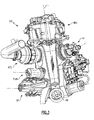
- An accessory gearbox 60 is mounted to the case structure 44 generally parallel to the engine axis of rotation A.
- the accessory gearbox 60 takes advantage of the significant axial area within the core nacelle C ( Figure 1 ) to support an engine accessory system 62 which may include accessory components (AC)s such as an Air Turbine Starter (ATS), a deoiler (D), a hydraulic pump (HP), an oil pump (OP), an integrated drive generator (IDG), a permanent magnet alternator (PMA), a fuel pump module (FPM), and others ( Figure 3 ).
- AC Air Turbine Starter
- D deoiler
- HP hydraulic pump
- OP oil pump
- IDG integrated drive generator
- PMA permanent magnet alternator
- FPM fuel pump module
- Figure 3 any number and type of accessory components AC may alternatively or additionally be provided.
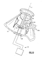
- the accessory gearbox 60 includes a housing assembly 64 which at least partially supports a towershaft 66 and layshaft 68.
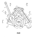
- the towershaft 66 defines a towershaft axis of rotation T generally transverse to the engine axis of rotation A from which the towershaft 66 extends ( Figure 2 ). It should be understood that the towershaft 66 is in meshing engagement and typically driven by the high spool 24. Various towershaft 66 arrangements will benefit herefrom.
- the layshaft 68 defines a layshaft axis of rotation L generally parallel to the engine axis of rotation A ( Figure 2 ). That is, the housing assembly 64 provides an integral housing for the towershaft 66 and the layshaft 68 which otherwise conventionally required a separate angled gearbox housing which extends from the crescent shaped accessory gearbox.
- the housing assembly 64 includes a main case 74, a first cover 76 and a second cover 78.
- the main case 74 includes support points 70A, 70B for attachment to the case structure 44 through a multiple of links 72 which constrain relative movement of the housing assembly 64 in six-degrees of freedom. It should be understood that various attachment arrangements may additionally or alternatively be provided.
- the covers 76, 78 define angled, non-parallel sides of the housing assembly 64.
- the covers 76, 78 are removable to access a geartrain 80 ( Figure 6 ). It should be understood that various other covers and access panels may alternatively or additionally be provided.
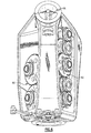
- the covers 76, 78 define an accessory component pad 82A-82E to which the associated accessory component AC is mounted.
- the accessory component pads 82A-82E facilitate a V-orientation of the accessory components AC ( Figures 7 and 8 ) with respect to the main case 74 to essentially straddle the engine case structure 44. That is, a mounting axis b of each accessory component AC on the first cover 76 and a mounting axis c of each accessory component AC on the second cover 78 define the V-orientation with respect to the layshaft axis of rotation L to straddle the engine axis of rotation A.
- This orientation provides a significant removability envelope for each accessory component AC as each accessory component AC extends in a radial outboard direction with regard to the layshaft axis of rotation L.
- the location of the accessory components AC also facilitates location of the accessory gearbox 60 and the accessory components AC forward within the core nacelle which provides a relatively lower temperature operating environment.
- the location of the accessory components AC further facilitates service line routes which typically require a relatively large bend radius R ( Figure 9 ).
- the first cover 76 may additionally include a manifold 84.
- the manifold 84 may be a fuel manifold which supports a multiple of fluidly connected components such as a fuel pump, FMU and a fuel filter in a module arrangement.
- the Integral Drive Generator is mounted along the layshaft axis of rotation L (best seen in Figures 2 and 3 ). That is, the layshaft axis of rotation L may be in line with the input axis of rotation for the IDG.
- the axial arrangement of the IDG and layshaft 68 provides a mounted location where there is more room for a relatively larger more powerful generators.
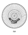
- the geartrain 80 includes a multiple of drive gears 86A-86E which may be interconnected by a multiple of idler gears 88A-88B.
- the geartrain 80 within the accessory gearbox section 60 drives each auxiliary engine component AC at the proper speed. That is, each drive gear 86A-86E drives the respective accessory component AC.
- the towershaft 66 is supported within the main case 74 in meshing engagement with the layshaft 68 through a first gear arrangement 90A such as a bevel gear arrangement.
- the layshaft 68 is supported within the main case 74 ( Figure 5D ) to drive a second gear arrangement 90B which may include a bevel gear 90B which is in meshing engagement with drive gears 86A and 86E (shown in Fig 5C ). That is, the bevel gear 90B is in meshing engagement with drive gears 86A and 86E to drive the entire geartrain 80.
- the layshaft 68 is supported within housing assembly 64 through bearing supports 92 within the main case 74.
- the integration of towershaft 66 (not shown), layshaft 68 and geartrain 80 (not shown) within the main case 74 provides a significant overall weight reduction.
- the location of the layshaft 68 within the main case 74 facilitates lubrication as well as common lubrication system integration of the towershaft 66 (not shown), the layshaft 68 and the geartrain 80 (not shown).
- the towershaft 66 may also include a socket 94 adjacent the first gear arrangement 90A to receive a manual crank (illustrated schematically at M) which will facilitate maintenance and other operations.
- An access port 96 is located through the main case 74 along the towershaft axis of rotation T to provide attachment of the manual crank M in a readily accessible and operable location.
- the accessory gearbox 60 reduces component complexity, part count, and weight through elimination of bolted flanges and additional structure typical of a separate angled gearbox housing. This integration is best implemented for accessory gearboxes mounted close to the engine case, and in the case of this disclosure, gearboxes which are axially-oriented.
Landscapes
- Engineering & Computer Science (AREA)
- Chemical & Material Sciences (AREA)
- Combustion & Propulsion (AREA)
- Mechanical Engineering (AREA)
- General Engineering & Computer Science (AREA)
- Retarders (AREA)
- Supercharger (AREA)
Claims (7)
- Zusatzsystem (62) für eine Gasturbinenmaschine (10) umfassend:ein Zusatzgetriebegehäuse (60);eine Vorgelegewelle (68) innerhalb des Zusatzgetriebegehäuses (60) entlang einer Vorgelegewellen-Rotationsachse (L), wobei die Vorgelegewellen-Rotationsachse (L) parallel zu einer Gasturbinenmaschinen-Rotationsachse (A) ist;eine erste Zusatzkomponente (AC), die an dem Zusatzgetriebegehäuse (60) entlang einer ersten Zusatzachse (b), schräg zu der Vorgelegewellen-Rotationsachse (L) angebracht ist;eine zweite Zusatzkomponente, die an dem Zusatzgetriebegehäuse (60) entlang einer zweiten Zusatzachse, schräg (c) zu der Vorgelegewellen-Rotationsachse (L) angebracht ist, wobei die erste Zusatzachse (b) und die zweite Zusatzachse (c) eine V-Ausrichtung definieren; undeine Schachtwelle (66) in Eingriffszusammenwirkung mit der Vorgegelegewelle (68), wobei die Schachtwelle (66) schräg zu der Gasturbinenmaschinen-Rotationsachse (A) ist, wobei die Schachtwelle (66) zum Antrieb der Vorgegelegewelle (68) ist, wobei die Vorgelegewelle (68) die erste und die zweite Zusatzkomponente (AC) antreibt.
- Zusatzsystem nach Anspruch 1, wobei die erste Zusatzachse (b) schräg zu der Gasturbinenmaschinen-Rotationsachse (A) ist.
- Zusatzsystem nach Anspruch 1 oder 2, wobei die erste Zusatzachse (b) und die zweite Zusatzachse (c) die Gasturbinen-Rotationsachse (A) überspannen.
- Zusatzsystem nach einem der vorangehenden Ansprüche, wobei die erste Zusatzkomponente (AC) an einer entfernbaren Abdeckung (76) des Zusatzgetriebegehäuses (60) angebracht ist.
- Zusatzsystem nach Anspruch 4, wobei die zweite Zusatzkomponente (AC) an einer zweiten entfernbaren Abdeckung (78) des Zusatzgetriebegehäuses (60) angebracht ist.
- Gasturbinenmaschine umfassend:einen Maschinengehäusebereich (44), der um die Gasturbinenmaschinen-Rotationsachse (A) definiert ist;
ein Zusatzgetriebegehäuse nach einem der vorangehenden Ansprüche, das an dem Maschinengehäusebereich (44) angebracht ist. - Gasturbinenmaschine nach Anspruch 6, wobei der Maschinengehäusebereich (44) ein Maschinenkemgehäusebereich ist.
Applications Claiming Priority (1)
| Application Number | Priority Date | Filing Date | Title |
|---|---|---|---|
| US12/787,385 US8347637B2 (en) | 2010-05-25 | 2010-05-25 | Accessory gearbox with internal layshaft |
Publications (3)
| Publication Number | Publication Date |
|---|---|
| EP2390486A2 EP2390486A2 (de) | 2011-11-30 |
| EP2390486A3 EP2390486A3 (de) | 2012-06-27 |
| EP2390486B1 true EP2390486B1 (de) | 2013-09-18 |
Family
ID=44117896
Family Applications (1)
| Application Number | Title | Priority Date | Filing Date |
|---|---|---|---|
| EP11167168.1A Active EP2390486B1 (de) | 2010-05-25 | 2011-05-23 | Nebenaggregate-Getriebe mit Vorgelegewelle |
Country Status (2)
| Country | Link |
|---|---|
| US (1) | US8347637B2 (de) |
| EP (1) | EP2390486B1 (de) |
Families Citing this family (56)
| Publication number | Priority date | Publication date | Assignee | Title |
|---|---|---|---|---|
| US20110146434A1 (en) * | 2009-12-18 | 2011-06-23 | Short Keith E | Jack shaft disconnect |
| US20110239660A1 (en) * | 2010-03-30 | 2011-10-06 | United Technologies Corporation | Mounting arrangement for gas turbine engine accessories and gearbox therefor |
| US8490410B2 (en) | 2010-11-17 | 2013-07-23 | United Technologies Corporation | Axial accessory gearbox |
| US8490411B2 (en) | 2010-11-17 | 2013-07-23 | United Technologies Corporation | Axial accessory gearbox |
| EP2522832B1 (de) * | 2011-05-09 | 2014-08-06 | United Technologies Corporation | Axialer Hilfsgeräteantrieb |
| US9068515B2 (en) | 2011-12-07 | 2015-06-30 | United Technologies Corporation | Accessory gearbox with tower shaft removal capability |
| US20130180262A1 (en) * | 2012-01-18 | 2013-07-18 | Hung Duong | Gas turbine engine accessory gearbox |
| US9097186B2 (en) * | 2012-01-29 | 2015-08-04 | United Technologies Corporation | Bevel gear arrangement for axial accessory gearbox |
| US9394803B2 (en) * | 2012-03-14 | 2016-07-19 | United Technologies Corporation | Bypass air-pump system within the core engine to provide air for an environmental control system in a gas turbine engine |
| US9163562B2 (en) * | 2012-03-14 | 2015-10-20 | United Technologies Corporation | Constant speed pump system for engine ECS loss elimination |
| US9151224B2 (en) * | 2012-03-14 | 2015-10-06 | United Technologies Corporation | Constant-speed pump system for engine thermal management system AOC reduction and environmental control system loss elimination |
| US8973465B2 (en) * | 2012-07-20 | 2015-03-10 | United Technologies Corporation | Gearbox for gas turbine engine |
| US8992089B2 (en) | 2012-07-31 | 2015-03-31 | IMS Solutions | Layshaft end bearing retrofit with external positive oil pressure delivery |
| FR2995053B1 (fr) | 2012-09-03 | 2016-03-04 | Snecma | Boite d'engrenages de prise de mouvement sur une turbomachine, composee d'une chaine cinematique a lignes d'engrenages s'etendant dans des plans non paralleles |
| US10184404B2 (en) | 2012-09-20 | 2019-01-22 | United Technologies Corporation | Geared gas turbine engine accessory gearbox |
| US9879599B2 (en) * | 2012-09-27 | 2018-01-30 | United Technologies Corporation | Nacelle anti-ice valve utilized as compressor stability bleed valve during starting |
| WO2014120134A1 (en) * | 2013-01-30 | 2014-08-07 | United Technologies Corporation | Gas turbine engine accessory gearbox |
| US20140252160A1 (en) * | 2013-03-07 | 2014-09-11 | United Technologies Corporation | Reverse flow gas turbine engine removable core |
| US8829702B1 (en) | 2013-03-11 | 2014-09-09 | Pratt & Whitney Canada Corp | Gas turbine engine with internal electromechanical device |
| US9003638B2 (en) | 2013-03-11 | 2015-04-14 | Pratt & Whitney Canada Corp. | Method of assembling an electromechanical device in a gas-turbine engine |
| FR3003323B1 (fr) | 2013-03-14 | 2016-10-07 | Snecma | Fixation d'une boite d'engrenages en v sur une turbomachine |
| WO2015017095A2 (en) | 2013-07-09 | 2015-02-05 | United Technologies Corporation | Plated polymer nosecone |
| WO2015006421A1 (en) | 2013-07-09 | 2015-01-15 | United Technologies Corporation | Metal-encapsulated polymeric article |
| EP3019721B1 (de) * | 2013-07-09 | 2020-02-26 | United Technologies Corporation | Plattierte polymergondel |
| US10927843B2 (en) | 2013-07-09 | 2021-02-23 | Raytheon Technologies Corporation | Plated polymer compressor |
| CA2917884A1 (en) | 2013-07-09 | 2015-01-15 | United Technologies Corporation | Plated polymer fan |
| FR3011882B1 (fr) * | 2013-10-11 | 2018-01-26 | Hispano Suiza Sa | Boitier d'entrainement d'accessoires pour turbomachine |
| WO2015088830A1 (en) | 2013-12-10 | 2015-06-18 | United Technologies Corporation | System and apparatus for interchangeable smart gearbox |
| FR3014954B1 (fr) * | 2013-12-12 | 2018-12-07 | Safran Transmission Systems | Boite d'engrenages a fixer a une turbomachine comprenant une division de la chaine cinematique |
| FR3016407B1 (fr) * | 2014-01-16 | 2016-02-19 | Hispano Suiza Sa | Boitier d'entrainement pour equipements |
| FR3017658B1 (fr) | 2014-02-18 | 2019-04-12 | Safran Transmission Systems | Boitier d'entrainement d'equipements pour turbomachine |
| US9951695B2 (en) | 2014-04-29 | 2018-04-24 | Honeywell International Inc. | Multi-axis accessory gearboxes of mechanical drive systems and gas turbine engines including the same |
| US9845735B2 (en) * | 2015-01-14 | 2017-12-19 | United Technologies Corporation | System and apparatus for diversified gearbox |
| US20160230843A1 (en) * | 2015-02-09 | 2016-08-11 | United Technologies Corporation | Gearbox for gas turbine engine |
| US10371055B2 (en) | 2015-02-12 | 2019-08-06 | United Technologies Corporation | Intercooled cooling air using cooling compressor as starter |
| US10221721B2 (en) | 2015-06-19 | 2019-03-05 | Hamilton Sundstrand Corporation | Hydraulic line routing plate |
| FR3041052B1 (fr) * | 2015-09-14 | 2018-07-27 | Safran Transmission Systems | Boitier d'entrainement d'equipements dans une turbomachine |
| US10662878B2 (en) | 2016-02-03 | 2020-05-26 | Honeywell Internatioanl Inc. | Compact accessory systems for a gas turbine engine |
| US9664070B1 (en) | 2016-02-12 | 2017-05-30 | United Technologies Corporation | Bowed rotor prevention system |
| US10040577B2 (en) | 2016-02-12 | 2018-08-07 | United Technologies Corporation | Modified start sequence of a gas turbine engine |
| US10539079B2 (en) | 2016-02-12 | 2020-01-21 | United Technologies Corporation | Bowed rotor start mitigation in a gas turbine engine using aircraft-derived parameters |
| US10508601B2 (en) * | 2016-02-12 | 2019-12-17 | United Technologies Corporation | Auxiliary drive bowed rotor prevention system for a gas turbine engine |
| US10590852B2 (en) | 2017-01-19 | 2020-03-17 | United Technologies Corporation | Gas turbine engine dual towershaft accessory gearbox assembly with a transmission |
| US10590853B2 (en) | 2017-01-19 | 2020-03-17 | United Technologies Corporation | Gas turbine engine dual towershaft accessory gearbox assembly with a transmission |
| US10422243B2 (en) | 2017-01-19 | 2019-09-24 | United Technologies Corporation | Gas turbine engine dual towershaft accessory gearbox and starter generator assembly |
| US10995673B2 (en) | 2017-01-19 | 2021-05-04 | Raytheon Technologies Corporation | Gas turbine engine with intercooled cooling air and dual towershaft accessory gearbox |
| US10502142B2 (en) * | 2017-04-11 | 2019-12-10 | United Technologies Corporation | Turbine engine gearbox assembly with sets of inline gears |
| US10526976B2 (en) * | 2017-04-27 | 2020-01-07 | United Technologies Corporation | Tangential drive for gas turbine engine accessories |
| US10823080B2 (en) | 2017-05-31 | 2020-11-03 | General Electric Company | Dual accessory gearbox |
| FR3070726B1 (fr) | 2017-09-07 | 2019-08-23 | Safran Transmission Systems | Boitier d'accessoires pour turbomachine |
| GB201806028D0 (en) * | 2018-04-12 | 2018-05-30 | Rolls Royce Plc | Accessory gearbox |
| US10519870B2 (en) * | 2018-06-04 | 2019-12-31 | United Technologies Corporation | Multiple mounting surface gearbox |
| US11608784B2 (en) * | 2019-02-13 | 2023-03-21 | Raytheon Technologies Corporation | Accessory gearbox for gas turbine engine with compressor drive |
| US10995675B2 (en) | 2019-02-19 | 2021-05-04 | Pratt & Whitney Canada Corp. | Gas turbine engine with accessory gearbox |
| FR3123377B1 (fr) * | 2021-05-27 | 2023-05-19 | Safran Aircraft Engines | Ensemble de supportage d’une boite d’accessoires d’une turbomachine d'aéronef |
| FR3161001B1 (fr) * | 2024-04-05 | 2026-02-27 | Safran Aircraft Engines | Equipement pour système d’entraînement d’une turbomachine, système d’entraînement, turbomachine et aéronef associés |
Family Cites Families (39)
| Publication number | Priority date | Publication date | Assignee | Title |
|---|---|---|---|---|
| US2470155A (en) | 1942-05-16 | 1949-05-17 | Fairey Aviat Co Ltd | Power plant assembly |
| US2596363A (en) | 1945-10-29 | 1952-05-13 | Breguet Louis | Power transmission means for coaxial gyroplane rotors |
| GB626036A (en) | 1947-08-08 | 1949-07-07 | Bristol Aeroplane Co Ltd | Improvements in or relating to gas-turbine engines |
| US2803943A (en) | 1953-12-30 | 1957-08-27 | Armstrong Siddeley Motors Ltd | Means for supporting and driving accessories which are exterior to a ductedfan turbo-jet engine |
| CH342473A (fr) | 1954-03-15 | 1959-11-15 | Napier & Son Ltd | Hélicoptère pourvu d'un groupe à turbine à gaz |
| US2978869A (en) * | 1956-11-01 | 1961-04-11 | Bristol Siddeley Engines Ltd | Engine accessory mounting arrangements |
| GB839961A (en) | 1956-11-01 | 1960-06-29 | Bristol Siddeley Engines Ltd | Improvements in or relating to engine accessory mounting arrangements |
| US3050275A (en) | 1959-05-28 | 1962-08-21 | United Aircraft Corp | Steam driven helicopter rotor head |
| US3332242A (en) | 1965-03-31 | 1967-07-25 | Gen Motors Corp | Aft fan jet engine |
| US3269118A (en) | 1965-04-28 | 1966-08-30 | United Aircraft Corp | Accessory case mounting |
| US3455182A (en) | 1967-04-12 | 1969-07-15 | Garrett Corp | Helicopter lift augmentation means |
| US3543588A (en) | 1968-11-12 | 1970-12-01 | Gen Motors Corp | Accessory installation |
| GB1523714A (en) | 1971-12-13 | 1978-09-06 | Westland Aircraft Ltd | Helicopters |
| US3799473A (en) | 1972-04-21 | 1974-03-26 | V Bortel | Rotary wing aircraft and drive means therefor |
| FR2232481B1 (de) | 1973-06-08 | 1976-05-07 | Aerospatiale | |
| US3977632A (en) | 1974-02-18 | 1976-08-31 | Westland Aircraft Limited | Helicopter power transmission systems |
| FR2474996A1 (fr) | 1980-02-05 | 1981-08-07 | Aerospatiale | Dispositif de suspension antiresonnante pour helicoptere |
| US4632337A (en) | 1981-09-21 | 1986-12-30 | Hughes Helicopters, Inc. | Helicopter rotor transmission systems |
| US4437627A (en) | 1982-03-12 | 1984-03-20 | The Boeing Company | Integrated power plant installation system |
| EP0091744A1 (de) | 1982-04-08 | 1983-10-19 | WESTLAND plc | Antrieb für einen Hubschrauber |
| US4489625A (en) | 1982-11-23 | 1984-12-25 | Transmission Research, Inc. | Split torque transmission |
| US4525995A (en) | 1983-04-04 | 1985-07-02 | Williams International Corporation | Oil scavening system for gas turbine engine |
| IT1179694B (it) | 1984-05-29 | 1987-09-16 | Agusta Aeronaut Costr | Assieme motore trasmissione per elicottero |
| GB8625712D0 (en) | 1986-10-28 | 1987-03-18 | Westland Plc | Transmission system |
| DE3708596A1 (de) | 1987-03-17 | 1988-09-29 | Mtu Muenchen Gmbh | Gasturbinenanlage fuer hubschrauber |
| US5687561A (en) | 1991-09-17 | 1997-11-18 | Rolls-Royce Plc | Ducted fan gas turbine engine accessory drive |
| FR2698911B1 (fr) | 1992-12-09 | 1995-01-06 | Snecma | Agencement de moteur d'avion. |
| US6357220B1 (en) | 1998-12-22 | 2002-03-19 | United Technologies Corporation | Gearbox accessory mount |
| US6364249B1 (en) | 1999-09-30 | 2002-04-02 | Pratt & Whitney Canada Corp. | Engine integrated with rotary wing aircraft transmission |
| JP4490553B2 (ja) | 2000-04-28 | 2010-06-30 | 本田技研工業株式会社 | ガスタービンエンジンの補機駆動ユニット |
| US6851267B2 (en) | 2002-12-18 | 2005-02-08 | Pratt & Whitney Canada Corp. | Compact quick attach starter-generator installation |
| GB0311663D0 (en) | 2003-05-21 | 2003-06-25 | Rolls Royce Plc | Aeroengine intake |
| US7500365B2 (en) | 2005-05-05 | 2009-03-10 | United Technologies Corporation | Accessory gearbox |
| US7500935B2 (en) | 2005-06-23 | 2009-03-10 | Karem Aircraft, Inc. | Lightweight reduction gearbox |
| US20080148881A1 (en) | 2006-12-21 | 2008-06-26 | Thomas Ory Moniz | Power take-off system and gas turbine engine assembly including same |
| US8162605B2 (en) | 2008-01-14 | 2012-04-24 | United Technologies Corporation | Gas turbine engine case |
| US20090188334A1 (en) | 2008-01-25 | 2009-07-30 | United Technologies Corp. | Accessory Gearboxes and Related Gas Turbine Engine Systems |
| US8192143B2 (en) | 2008-05-21 | 2012-06-05 | United Technologies Corporation | Gearbox assembly |
| US8210800B2 (en) | 2008-06-12 | 2012-07-03 | United Technologies Corporation | Integrated actuator module for gas turbine engine |
-
2010
- 2010-05-25 US US12/787,385 patent/US8347637B2/en active Active
-
2011
- 2011-05-23 EP EP11167168.1A patent/EP2390486B1/de active Active
Also Published As
| Publication number | Publication date |
|---|---|
| EP2390486A3 (de) | 2012-06-27 |
| US20110289936A1 (en) | 2011-12-01 |
| EP2390486A2 (de) | 2011-11-30 |
| US8347637B2 (en) | 2013-01-08 |
Similar Documents
| Publication | Publication Date | Title |
|---|---|---|
| EP2390486B1 (de) | Nebenaggregate-Getriebe mit Vorgelegewelle | |
| EP3032072B1 (de) | Axiales hilfsgetriebe | |
| US8490411B2 (en) | Axial accessory gearbox | |
| US10001059B2 (en) | Accessory gearbox with tower shaft removal capability | |
| US9719428B2 (en) | Gas turbine engine with pylon mounted accessory drive | |
| US9816441B2 (en) | Gas turbine engine with stacked accessory components | |
| US8333554B2 (en) | Split gearbox and nacelle arrangement | |
| EP2898205B1 (de) | Hilfsgetriebe für gasturbinenmotor | |
| EP2872762B1 (de) | Mittelturbinenrahmen mit ölsystembefestigungen und entsprechendes verfahren | |
| EP2133514A2 (de) | Integriertes Aktuatormodul für Gasturbinenmotor | |
| EP2959129B1 (de) | In eine schmiermittelhauptpumpstufe integrierte zusätzliche schmiermittelversorgungspumpstufe | |
| EP2855881A1 (de) | Gondelgabelung für einem gasturbinenmotor | |
| EP2522832B1 (de) | Axialer Hilfsgeräteantrieb | |
| EP3379056B1 (de) | Zweiwelliger abtriebswellenträger sowie montageverfahren | |
| CN112443652A (zh) | 具有收集器的用于航空发动机的齿轮组件 | |
| EP4589133A1 (de) | Komponentenmontage und -antrieb in einer getriebeturbolüfterarchitektur | |
| EP2604810A2 (de) | Integriertes Aktuatormodul für einen Gasturbinenmotor | |
| EP4585796A1 (de) | Komponentenmontage und -antrieb in einer getriebeturbolüfterarchitektur |
Legal Events
| Date | Code | Title | Description |
|---|---|---|---|
| AK | Designated contracting states |
Kind code of ref document: A2 Designated state(s): AL AT BE BG CH CY CZ DE DK EE ES FI FR GB GR HR HU IE IS IT LI LT LU LV MC MK MT NL NO PL PT RO RS SE SI SK SM TR |
|
| AX | Request for extension of the european patent |
Extension state: BA ME |
|
| PUAI | Public reference made under article 153(3) epc to a published international application that has entered the european phase |
Free format text: ORIGINAL CODE: 0009012 |
|
| PUAL | Search report despatched |
Free format text: ORIGINAL CODE: 0009013 |
|
| AK | Designated contracting states |
Kind code of ref document: A3 Designated state(s): AL AT BE BG CH CY CZ DE DK EE ES FI FR GB GR HR HU IE IS IT LI LT LU LV MC MK MT NL NO PL PT RO RS SE SI SK SM TR |
|
| AX | Request for extension of the european patent |
Extension state: BA ME |
|
| RIC1 | Information provided on ipc code assigned before grant |
Ipc: F02C 7/32 20060101AFI20120524BHEP |
|
| 17P | Request for examination filed |
Effective date: 20121221 |
|
| GRAP | Despatch of communication of intention to grant a patent |
Free format text: ORIGINAL CODE: EPIDOSNIGR1 |
|
| INTG | Intention to grant announced |
Effective date: 20130415 |
|
| GRAS | Grant fee paid |
Free format text: ORIGINAL CODE: EPIDOSNIGR3 |
|
| GRAA | (expected) grant |
Free format text: ORIGINAL CODE: 0009210 |
|
| AK | Designated contracting states |
Kind code of ref document: B1 Designated state(s): AL AT BE BG CH CY CZ DE DK EE ES FI FR GB GR HR HU IE IS IT LI LT LU LV MC MK MT NL NO PL PT RO RS SE SI SK SM TR |
|
| REG | Reference to a national code |
Ref country code: GB Ref legal event code: FG4D |
|
| REG | Reference to a national code |
Ref country code: CH Ref legal event code: EP |
|
| REG | Reference to a national code |
Ref country code: IE Ref legal event code: FG4D |
|
| REG | Reference to a national code |
Ref country code: AT Ref legal event code: REF Ref document number: 632930 Country of ref document: AT Kind code of ref document: T Effective date: 20131015 |
|
| REG | Reference to a national code |
Ref country code: DE Ref legal event code: R096 Ref document number: 602011003086 Country of ref document: DE Effective date: 20131114 |
|
| PG25 | Lapsed in a contracting state [announced via postgrant information from national office to epo] |
Ref country code: HR Free format text: LAPSE BECAUSE OF FAILURE TO SUBMIT A TRANSLATION OF THE DESCRIPTION OR TO PAY THE FEE WITHIN THE PRESCRIBED TIME-LIMIT Effective date: 20130918 Ref country code: NO Free format text: LAPSE BECAUSE OF FAILURE TO SUBMIT A TRANSLATION OF THE DESCRIPTION OR TO PAY THE FEE WITHIN THE PRESCRIBED TIME-LIMIT Effective date: 20131218 Ref country code: CY Free format text: LAPSE BECAUSE OF FAILURE TO SUBMIT A TRANSLATION OF THE DESCRIPTION OR TO PAY THE FEE WITHIN THE PRESCRIBED TIME-LIMIT Effective date: 20130731 Ref country code: LT Free format text: LAPSE BECAUSE OF FAILURE TO SUBMIT A TRANSLATION OF THE DESCRIPTION OR TO PAY THE FEE WITHIN THE PRESCRIBED TIME-LIMIT Effective date: 20130918 Ref country code: SE Free format text: LAPSE BECAUSE OF FAILURE TO SUBMIT A TRANSLATION OF THE DESCRIPTION OR TO PAY THE FEE WITHIN THE PRESCRIBED TIME-LIMIT Effective date: 20130918 |
|
| REG | Reference to a national code |
Ref country code: NL Ref legal event code: VDEP Effective date: 20130918 |
|
| REG | Reference to a national code |
Ref country code: AT Ref legal event code: MK05 Ref document number: 632930 Country of ref document: AT Kind code of ref document: T Effective date: 20130918 |
|
| REG | Reference to a national code |
Ref country code: LT Ref legal event code: MG4D |
|
| PG25 | Lapsed in a contracting state [announced via postgrant information from national office to epo] |
Ref country code: GR Free format text: LAPSE BECAUSE OF FAILURE TO SUBMIT A TRANSLATION OF THE DESCRIPTION OR TO PAY THE FEE WITHIN THE PRESCRIBED TIME-LIMIT Effective date: 20131219 Ref country code: LV Free format text: LAPSE BECAUSE OF FAILURE TO SUBMIT A TRANSLATION OF THE DESCRIPTION OR TO PAY THE FEE WITHIN THE PRESCRIBED TIME-LIMIT Effective date: 20130918 Ref country code: RS Free format text: LAPSE BECAUSE OF FAILURE TO SUBMIT A TRANSLATION OF THE DESCRIPTION OR TO PAY THE FEE WITHIN THE PRESCRIBED TIME-LIMIT Effective date: 20130918 Ref country code: FI Free format text: LAPSE BECAUSE OF FAILURE TO SUBMIT A TRANSLATION OF THE DESCRIPTION OR TO PAY THE FEE WITHIN THE PRESCRIBED TIME-LIMIT Effective date: 20130918 Ref country code: SI Free format text: LAPSE BECAUSE OF FAILURE TO SUBMIT A TRANSLATION OF THE DESCRIPTION OR TO PAY THE FEE WITHIN THE PRESCRIBED TIME-LIMIT Effective date: 20130918 |
|
| PG25 | Lapsed in a contracting state [announced via postgrant information from national office to epo] |
Ref country code: BE Free format text: LAPSE BECAUSE OF FAILURE TO SUBMIT A TRANSLATION OF THE DESCRIPTION OR TO PAY THE FEE WITHIN THE PRESCRIBED TIME-LIMIT Effective date: 20130918 Ref country code: CY Free format text: LAPSE BECAUSE OF FAILURE TO SUBMIT A TRANSLATION OF THE DESCRIPTION OR TO PAY THE FEE WITHIN THE PRESCRIBED TIME-LIMIT Effective date: 20130918 |
|
| PG25 | Lapsed in a contracting state [announced via postgrant information from national office to epo] |
Ref country code: IS Free format text: LAPSE BECAUSE OF FAILURE TO SUBMIT A TRANSLATION OF THE DESCRIPTION OR TO PAY THE FEE WITHIN THE PRESCRIBED TIME-LIMIT Effective date: 20140118 Ref country code: CZ Free format text: LAPSE BECAUSE OF FAILURE TO SUBMIT A TRANSLATION OF THE DESCRIPTION OR TO PAY THE FEE WITHIN THE PRESCRIBED TIME-LIMIT Effective date: 20130918 Ref country code: EE Free format text: LAPSE BECAUSE OF FAILURE TO SUBMIT A TRANSLATION OF THE DESCRIPTION OR TO PAY THE FEE WITHIN THE PRESCRIBED TIME-LIMIT Effective date: 20130918 Ref country code: SK Free format text: LAPSE BECAUSE OF FAILURE TO SUBMIT A TRANSLATION OF THE DESCRIPTION OR TO PAY THE FEE WITHIN THE PRESCRIBED TIME-LIMIT Effective date: 20130918 Ref country code: NL Free format text: LAPSE BECAUSE OF FAILURE TO SUBMIT A TRANSLATION OF THE DESCRIPTION OR TO PAY THE FEE WITHIN THE PRESCRIBED TIME-LIMIT Effective date: 20130918 |
|
| PG25 | Lapsed in a contracting state [announced via postgrant information from national office to epo] |
Ref country code: PL Free format text: LAPSE BECAUSE OF FAILURE TO SUBMIT A TRANSLATION OF THE DESCRIPTION OR TO PAY THE FEE WITHIN THE PRESCRIBED TIME-LIMIT Effective date: 20130918 Ref country code: ES Free format text: LAPSE BECAUSE OF FAILURE TO SUBMIT A TRANSLATION OF THE DESCRIPTION OR TO PAY THE FEE WITHIN THE PRESCRIBED TIME-LIMIT Effective date: 20130918 Ref country code: AT Free format text: LAPSE BECAUSE OF FAILURE TO SUBMIT A TRANSLATION OF THE DESCRIPTION OR TO PAY THE FEE WITHIN THE PRESCRIBED TIME-LIMIT Effective date: 20130918 |
|
| REG | Reference to a national code |
Ref country code: DE Ref legal event code: R097 Ref document number: 602011003086 Country of ref document: DE |
|
| PG25 | Lapsed in a contracting state [announced via postgrant information from national office to epo] |
Ref country code: PT Free format text: LAPSE BECAUSE OF FAILURE TO SUBMIT A TRANSLATION OF THE DESCRIPTION OR TO PAY THE FEE WITHIN THE PRESCRIBED TIME-LIMIT Effective date: 20140120 |
|
| PLBE | No opposition filed within time limit |
Free format text: ORIGINAL CODE: 0009261 |
|
| STAA | Information on the status of an ep patent application or granted ep patent |
Free format text: STATUS: NO OPPOSITION FILED WITHIN TIME LIMIT |
|
| 26N | No opposition filed |
Effective date: 20140619 |
|
| PG25 | Lapsed in a contracting state [announced via postgrant information from national office to epo] |
Ref country code: IT Free format text: LAPSE BECAUSE OF FAILURE TO SUBMIT A TRANSLATION OF THE DESCRIPTION OR TO PAY THE FEE WITHIN THE PRESCRIBED TIME-LIMIT Effective date: 20130918 |
|
| PG25 | Lapsed in a contracting state [announced via postgrant information from national office to epo] |
Ref country code: DK Free format text: LAPSE BECAUSE OF FAILURE TO SUBMIT A TRANSLATION OF THE DESCRIPTION OR TO PAY THE FEE WITHIN THE PRESCRIBED TIME-LIMIT Effective date: 20130918 |
|
| REG | Reference to a national code |
Ref country code: DE Ref legal event code: R097 Ref document number: 602011003086 Country of ref document: DE Effective date: 20140619 |
|
| PG25 | Lapsed in a contracting state [announced via postgrant information from national office to epo] |
Ref country code: LU Free format text: LAPSE BECAUSE OF FAILURE TO SUBMIT A TRANSLATION OF THE DESCRIPTION OR TO PAY THE FEE WITHIN THE PRESCRIBED TIME-LIMIT Effective date: 20140523 |
|
| REG | Reference to a national code |
Ref country code: CH Ref legal event code: PL |
|
| PG25 | Lapsed in a contracting state [announced via postgrant information from national office to epo] |
Ref country code: CH Free format text: LAPSE BECAUSE OF NON-PAYMENT OF DUE FEES Effective date: 20140531 Ref country code: MC Free format text: LAPSE BECAUSE OF FAILURE TO SUBMIT A TRANSLATION OF THE DESCRIPTION OR TO PAY THE FEE WITHIN THE PRESCRIBED TIME-LIMIT Effective date: 20130918 Ref country code: LI Free format text: LAPSE BECAUSE OF NON-PAYMENT OF DUE FEES Effective date: 20140531 |
|
| REG | Reference to a national code |
Ref country code: IE Ref legal event code: MM4A |
|
| REG | Reference to a national code |
Ref country code: FR Ref legal event code: ST Effective date: 20150130 |
|
| PG25 | Lapsed in a contracting state [announced via postgrant information from national office to epo] |
Ref country code: IE Free format text: LAPSE BECAUSE OF NON-PAYMENT OF DUE FEES Effective date: 20140523 |
|
| PG25 | Lapsed in a contracting state [announced via postgrant information from national office to epo] |
Ref country code: FR Free format text: LAPSE BECAUSE OF NON-PAYMENT OF DUE FEES Effective date: 20140602 |
|
| PG25 | Lapsed in a contracting state [announced via postgrant information from national office to epo] |
Ref country code: MT Free format text: LAPSE BECAUSE OF FAILURE TO SUBMIT A TRANSLATION OF THE DESCRIPTION OR TO PAY THE FEE WITHIN THE PRESCRIBED TIME-LIMIT Effective date: 20130918 |
|
| PG25 | Lapsed in a contracting state [announced via postgrant information from national office to epo] |
Ref country code: SM Free format text: LAPSE BECAUSE OF FAILURE TO SUBMIT A TRANSLATION OF THE DESCRIPTION OR TO PAY THE FEE WITHIN THE PRESCRIBED TIME-LIMIT Effective date: 20130918 |
|
| PG25 | Lapsed in a contracting state [announced via postgrant information from national office to epo] |
Ref country code: RO Free format text: LAPSE BECAUSE OF FAILURE TO SUBMIT A TRANSLATION OF THE DESCRIPTION OR TO PAY THE FEE WITHIN THE PRESCRIBED TIME-LIMIT Effective date: 20130918 |
|
| PG25 | Lapsed in a contracting state [announced via postgrant information from national office to epo] |
Ref country code: BG Free format text: LAPSE BECAUSE OF FAILURE TO SUBMIT A TRANSLATION OF THE DESCRIPTION OR TO PAY THE FEE WITHIN THE PRESCRIBED TIME-LIMIT Effective date: 20130918 |
|
| PG25 | Lapsed in a contracting state [announced via postgrant information from national office to epo] |
Ref country code: HU Free format text: LAPSE BECAUSE OF FAILURE TO SUBMIT A TRANSLATION OF THE DESCRIPTION OR TO PAY THE FEE WITHIN THE PRESCRIBED TIME-LIMIT; INVALID AB INITIO Effective date: 20110523 Ref country code: TR Free format text: LAPSE BECAUSE OF FAILURE TO SUBMIT A TRANSLATION OF THE DESCRIPTION OR TO PAY THE FEE WITHIN THE PRESCRIBED TIME-LIMIT Effective date: 20130918 |
|
| REG | Reference to a national code |
Ref country code: DE Ref legal event code: R082 Ref document number: 602011003086 Country of ref document: DE Representative=s name: SCHMITT-NILSON SCHRAUD WAIBEL WOHLFROM PATENTA, DE |
|
| REG | Reference to a national code |
Ref country code: DE Ref legal event code: R082 Ref document number: 602011003086 Country of ref document: DE Representative=s name: SCHMITT-NILSON SCHRAUD WAIBEL WOHLFROM PATENTA, DE Ref country code: DE Ref legal event code: R081 Ref document number: 602011003086 Country of ref document: DE Owner name: UNITED TECHNOLOGIES CORP. (N.D.GES.D. STAATES , US Free format text: FORMER OWNER: UNITED TECHNOLOGIES CORPORATION, HARTFORD, CONN., US |
|
| PG25 | Lapsed in a contracting state [announced via postgrant information from national office to epo] |
Ref country code: MK Free format text: LAPSE BECAUSE OF FAILURE TO SUBMIT A TRANSLATION OF THE DESCRIPTION OR TO PAY THE FEE WITHIN THE PRESCRIBED TIME-LIMIT Effective date: 20130918 |
|
| PG25 | Lapsed in a contracting state [announced via postgrant information from national office to epo] |
Ref country code: AL Free format text: LAPSE BECAUSE OF FAILURE TO SUBMIT A TRANSLATION OF THE DESCRIPTION OR TO PAY THE FEE WITHIN THE PRESCRIBED TIME-LIMIT Effective date: 20130918 |
|
| REG | Reference to a national code |
Ref country code: DE Ref legal event code: R081 Ref document number: 602011003086 Country of ref document: DE Owner name: RAYTHEON TECHNOLOGIES CORPORATION (N.D.GES.D.S, US Free format text: FORMER OWNER: UNITED TECHNOLOGIES CORP. (N.D.GES.D. STAATES DELAWARE), FARMINGTON, CONN., US Ref country code: DE Ref legal event code: R081 Ref document number: 602011003086 Country of ref document: DE Owner name: RTX CORPORATION (N.D.GES.D. STAATES DELAWARE),, US Free format text: FORMER OWNER: UNITED TECHNOLOGIES CORP. (N.D.GES.D. STAATES DELAWARE), FARMINGTON, CONN., US |
|
| P01 | Opt-out of the competence of the unified patent court (upc) registered |
Effective date: 20230519 |
|
| PGFP | Annual fee paid to national office [announced via postgrant information from national office to epo] |
Ref country code: DE Payment date: 20250423 Year of fee payment: 15 |
|
| PGFP | Annual fee paid to national office [announced via postgrant information from national office to epo] |
Ref country code: GB Payment date: 20250423 Year of fee payment: 15 |
|
| REG | Reference to a national code |
Ref country code: DE Ref legal event code: R081 Ref document number: 602011003086 Country of ref document: DE Owner name: RTX CORPORATION (N.D.GES.D. STAATES DELAWARE),, US Free format text: FORMER OWNER: RAYTHEON TECHNOLOGIES CORPORATION (N.D.GES.D.STAATES DELAWARE), ARLINGTON, VA, US |