EP2390489B1 - Vorrichtung und Verfahren zur Bestimmung des Rückschwingwinkels einer angehaltenen Brennkraftmaschine - Google Patents
Vorrichtung und Verfahren zur Bestimmung des Rückschwingwinkels einer angehaltenen Brennkraftmaschine Download PDFInfo
- Publication number
- EP2390489B1 EP2390489B1 EP11167205A EP11167205A EP2390489B1 EP 2390489 B1 EP2390489 B1 EP 2390489B1 EP 11167205 A EP11167205 A EP 11167205A EP 11167205 A EP11167205 A EP 11167205A EP 2390489 B1 EP2390489 B1 EP 2390489B1
- Authority
- EP
- European Patent Office
- Prior art keywords
- crank
- time interval
- engine
- time
- pulse
- Prior art date
- Legal status (The legal status is an assumption and is not a legal conclusion. Google has not performed a legal analysis and makes no representation as to the accuracy of the status listed.)
- Active
Links
Images



Classifications
-
- F—MECHANICAL ENGINEERING; LIGHTING; HEATING; WEAPONS; BLASTING
- F02—COMBUSTION ENGINES; HOT-GAS OR COMBUSTION-PRODUCT ENGINE PLANTS
- F02D—CONTROLLING COMBUSTION ENGINES
- F02D41/00—Electrical control of supply of combustible mixture or its constituents
- F02D41/009—Electrical control of supply of combustible mixture or its constituents using means for generating position or synchronisation signals
-
- F—MECHANICAL ENGINEERING; LIGHTING; HEATING; WEAPONS; BLASTING
- F02—COMBUSTION ENGINES; HOT-GAS OR COMBUSTION-PRODUCT ENGINE PLANTS
- F02D—CONTROLLING COMBUSTION ENGINES
- F02D41/00—Electrical control of supply of combustible mixture or its constituents
- F02D41/009—Electrical control of supply of combustible mixture or its constituents using means for generating position or synchronisation signals
- F02D2041/0095—Synchronisation of the cylinders during engine shutdown
-
- F—MECHANICAL ENGINEERING; LIGHTING; HEATING; WEAPONS; BLASTING
- F02—COMBUSTION ENGINES; HOT-GAS OR COMBUSTION-PRODUCT ENGINE PLANTS
- F02D—CONTROLLING COMBUSTION ENGINES
- F02D2200/00—Input parameters for engine control
- F02D2200/02—Input parameters for engine control the parameters being related to the engine
- F02D2200/10—Parameters related to the engine output, e.g. engine torque or engine speed
- F02D2200/1012—Engine speed gradient
-
- F—MECHANICAL ENGINEERING; LIGHTING; HEATING; WEAPONS; BLASTING
- F02—COMBUSTION ENGINES; HOT-GAS OR COMBUSTION-PRODUCT ENGINE PLANTS
- F02D—CONTROLLING COMBUSTION ENGINES
- F02D2250/00—Engine control related to specific problems or objectives
- F02D2250/06—Reverse rotation of engine
-
- F—MECHANICAL ENGINEERING; LIGHTING; HEATING; WEAPONS; BLASTING
- F02—COMBUSTION ENGINES; HOT-GAS OR COMBUSTION-PRODUCT ENGINE PLANTS
- F02D—CONTROLLING COMBUSTION ENGINES
- F02D41/00—Electrical control of supply of combustible mixture or its constituents
- F02D41/02—Circuit arrangements for generating control signals
- F02D41/04—Introducing corrections for particular operating conditions
- F02D41/042—Introducing corrections for particular operating conditions for stopping the engine
Definitions
- the invention generally relates to controlling an internal combustion engine, and more particularly relates to determining a bounce back angle as part of estimating a stopped engine crank angle of the engine.
- United States Patent Number 7,360,406 to McDaniel et al. and EP 1 070 964 suggest a method for detecting engine reversal based on a calculated ratio that includes three time intervals between crank signal pulses being greater than a threshold.
- McDaniel's comparison to a single threshold is not able to detect engine reversal for all possible engine stopping conditions.
- McDaniel will not detect a direction reversal that results in a single crank signal pulse due to reverse crank rotation, and may double that error by incorrectly interpret that pulse as being due to forward crank rotation.
- United States Patent Number 7,142,973 to Ando suggests a method that controls the timing that stopping of engine is initiated so that the engine coasts to a stop in more predictable manner.
- Ando uses a predetermined coast-down model that relies on the engine being properly warmed up and operating at nominal operating conditions to coast-down to a stop in a predictable manner. If the engine is not warmed up, or not operating at nominal conditions, Ando does not attempt to determine a stopped engine crank angle and is silent with regard to estimating a bounce back angle.
- United States Patent Number 7,011,063 to Condemine et al. suggests another method that delivers fuel to at least one cylinder while the engine is coasting to a stop to more accurately control the coast-down process. However, such a method may increase fuel consumption and increase engine emissions due to incomplete fuel combustion.
- an engine control system for determining a bounce back angle of an internal combustion engine.
- the system includes a crank sensor and a controller.
- the crank sensor is configured to output a crank signal indicative of a crank angle and a crank speed.
- the controller is configured to determine the crank speed, determine that the engine is coasting, and determine the bounce back angle based on the crank signal following an engine reversal.
- the controller indicates the engine reversal when a crank speed decrease is greater than a crank speed decrease threshold.
- an engine controller for determining a bounce back angle of an internal combustion engine.
- the controller is configured to receive a crank signal indicative of a crank angle and a crank speed.
- the controller is configured to receive a crank signal indicative of a crank angle and a crank speed, determine the crank speed, determine that the engine is coasting, and determine the bounce back angle based on the crank signal following an engine reversal.
- the controller indicates the engine reversal when a crank speed decrease is greater than a crank speed decrease threshold.
- a crank sensor 16 is positioned proximate to the crank wheel 14 such that the crank sensor 16 is able to sense rotational movement of the crank wheel teeth.
- the crank wheel 14 and the teeth are made from a ferrous material, such as steel.
- the teeth influence the magnetic field in a way that may be detected, particularly when the crank speed is greater than a threshold speed. It is well known how the arrangement of fifty-eight evenly spaced crank wheel teeth combined with an eighteen degree gap corresponding to a missing fifty-ninth and sixtieth tooth provides for the crank sensor 16 to output a crank signal 18 indicative of a crank angle and a crank speed.
- the crank angle and crank speed may be used by the controller 20 to control the operation of a device 24.
- the device 24 may be a spark plug or a fuel injector.
- the presence of the spark plug implies that the engine is a spark ignition type engine.
- the determination of crank rotation direction and subsequent engine bounce-back may also be used on a compression ignition type engine.
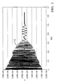
- the crank speed 18 may also be used to determine that the engine 12 is coasting. As used herein, coasting means that the engine speed is decreasing and the engine is expected to stop. This may also be referred to as a coast-down event.
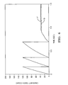
- the engine may reverse direction due to residual compression of air in one or more cylinders. Since the crank speed is determined based on time intervals, then an engine reversal may be indicated when a first time interval DT1 is greater than a second time interval DT2 by at least first threshold amount, wherein the second time interval DT2 occurs before the first time interval DT 1. It is noted that such a test is able to detect reverse rotation of an engine that is followed by only one crank sensor pulse. This stands in contrast to a method for detecting engine reversals described by McDaniel ( US Patent No.
- the routine 500 waits for a falling edge (-ve) of the crank signal 18.
- the routine 500 proceeds to step 520 where a new first pulse time T1 is determined.
- the new first pulse time T1 may update a buffer of pulse time generated as indicated in step 590.
- an engine speed may be calculated based on a first time interval DT1 between the first pulse time T1 and the second pulse time T2.
- a determination is made to see if the engine 12 is in the process of coasting to a stop.
- the engine 12 may be coasting to a stop if an ENGINE_SPEED is less than 600 revolutions per minute (RPM).
- the system 10 or controller 20 could continue to count pulses from the crank sensor 16 if engine bounce back occurs, and thereby better estimate the stopped engine crank angle. Without an indication that an engine reversal had occurred, the pulses from the crank sensor 16 occurring during bounce back would be interpreted as forward rotation of the crank wheel 14 and thereby degrade the accuracy of the stopped engine crank angle estimate.
- a difference between the first time interval DT1 and the second time interval DT2 is compared to a threshold. If DT1 is greater than DT2, then there is an indication that the engine 12 may be decelerating. As the engine 12 coasts to a stop, the ENGINE_SPEED may periodically increase or decrease due to combustion chamber decompression. However it has been observed that the deceleration indicated by the difference in time intervals that occurs just prior to an engine reversal may be larger than decelerations experienced otherwise during coast down. As such if the difference indicates a deceleration greater that a crank speed decrease threshold, then that may be an indication that an engine reversal has occurred.
- step 545 if DT1 - DT2 > 15000, then there may be an indication that an engine reversal has occurred since a corresponding crank speed decrease is greater than a crank speed decrease threshold. As such, an engine reversal is indicated and so the routine 500 jumps to step 550 where the sign of the direction variable REVERSE is inverted so the most recent pulse and subsequent pulses are used to decrease the TRUE_CRANK_ANGLE so that reverse rotation of the crank 14 may be properly accounted for using the formula illustrated in step 580.
- the threshold value of 15000 shown here is a non-limiting exemplary value that may change depending on the type of engine, engine displacement, engine age, or other engine operating conditions.
- a fourth pulse time T4 may be used to determined a third time interval DT3 based on a difference of the third pulse time T3 and the fourth pulse time T4.
- step 585 the various time intervals DT4, DT3, and DT2 are updated in preparation for receiving a new first time pulse T1 a step 515 and 520.
- step 590 the various pulse times T4, T3, and T2 are updated in preparation for receiving a new first time pulse T1 a step 515 and 520.
- a system 10, a controller 20 and a method 500 for determining engine reversals during a coast down event and determining a bounce back angle of an internal combustion engine is provided.
- a crank signal is analyzed to determine if an engine reversal has occurred.
- a bounce back angle corresponding to how much reverse rotation of the coasting engine occurs is determined.
Landscapes
- Engineering & Computer Science (AREA)
- Chemical & Material Sciences (AREA)
- Combustion & Propulsion (AREA)
- Mechanical Engineering (AREA)
- General Engineering & Computer Science (AREA)
- Combined Controls Of Internal Combustion Engines (AREA)
Claims (16)
- Ein System zum Bestimmen eines Rückprall-Winkels eines Verbrennungsmotors, wobei das System aufweist:einen Kurbelwellensensor, der konfiguriert ist, ein Kurbelwellensignal auszugeben, das einen Kurbelwellenwinkel und eine Kurbelwellengeschwindigkeit angibt; undeine Steuervorrichtung, die konfiguriert ist zum(a) Bestimmen der Kurbelwellengeschwindigkeit,(b) Bestimmen, dass der Motor im Leerlauf läuft,(c) Anzeigen einer Motorumkehr, wenn eine Abnahme einer Kurbelwellengeschwindigkeit größer ist als eine Kurbelwellengeschwindigkeit-Abnahmeschwelle, und(d) Bestimmen des Rückprall-Winkels basierend auf dem Kurbelwellensignal nach der Anzeige der Motorumkehr.
- Das System gemäß Anspruch 1, wobei das Kurbelwellensignal eine Vielzahl von Pulsen aufweist, die Kurbelwellengeschwindigkeit durch ein Zeitintervall zwischen Pulsen angezeigt wird, und die Abnahme der Kurbelwellengeschwindigkeit größer ist als die Kurbelwellengeschwindigkeit-Abnahmeschwelle, wenn ein erstes Zeitintervall um zumindest einen ersten Schwellenbetrag größer ist als ein zweites Zeitintervall, wobei das zweite Zeitintervall vor dem ersten Zeitintervall stattfindet.
- Das System gemäß Anspruch 2, wobei die Steuervorrichtung weiter konfiguriert ist, die Motorumkehr anzugeben, wenn das zweite Zeitintervall größer ist als das erste Zeitintervall, das zweite Zeitintervall größer ist als ein drittes Zeitintervall und das zweite Zeitintervall größer ist als ein zweiter Schwellenbetrag, wobei das dritte Zeitintervall vor dem zweiten Zeitintervall stattfindet.
- Das System gemäß Anspruch 3, wobei das erste Zeitintervall einem Zeitintervall zwischen einem ersten Pulszeitpunkt und einem zweiten Pulszeitpunkt entspricht, das zweite Zeitintervall einem Zeitintervall zwischen dem zweiten Pulszeitpunkt und einem dritten Pulszeitpunkt entspricht, und das dritte Zeitintervall einem Zeitintervall zwischen dem dritten Pulszeitpunkt und einem vierten Pulszeitpunkt entspricht, wobei der vierte Pulszeitpunkt dem dritten Pulszeitpunkt vorausgeht, der dritte Pulszeitpunkt dem zweiten Pulszeitpunkt vorausgeht, und der zweite Pulszeitpunkt dem ersten Pulszeitpunkt vorausgeht.
- Das System gemäß Anspruch 4, wobei der erste Pulszeitpunkt angrenzend an den zweiten Pulszeitpunkt ist, der zweite Pulszeitpunkt angrenzend an den dritten Pulszeitpunkt ist und der dritte Pulszeitpunkt angrenzend an den vierten Pulszeitpunkt ist.
- Eine Steuervorrichtung zum Bestimmen eines Rückprall-Winkels eines Verbrennungsmotors, wobei die Steuervorrichtung konfiguriert ist zum Empfangen eines Kurbelwellensignals, das einen Kurbelwellenwinkel und eine Kurbelwellengeschwindigkeit angibt, und zum(a) Bestimmen der Kurbelwellengeschwindigkeit,(b) Bestimmen, dass der Motor im Leerlauf läuft,(c) Anzeigen einer Motorumkehr, wenn eine Abnahme einer Kurbelwellengeschwindigkeit größer ist als eine Kurbelwellengeschwindigkeit-Abnahmeschwelle, und(d) Bestimmen des Rückprall-Winkels basierend auf dem Kurbelwellensignal nach der Anzeige der Motorumkehr.
- Die Steuervorrichtung gemäß Anspruch 6, wobei das Kurbelwellensignal eine Vielzahl von Pulsen aufweist, die Kurbelwellengeschwindigkeit durch ein Zeitintervall zwischen Pulsen angezeigt wird, und die Abnahme der Kurbelwellengeschwindigkeit größer ist als die Kurbelwellengeschwindigkeit-Abnahmeschwelle, wenn ein erstes Zeitintervall um zumindest einen ersten Schwellenbetrag größer ist als ein zweites Zeitintervall, wobei das zweite Zeitintervall vor dem ersten Zeitintervall stattfindet.
- Die Steuervorrichtung gemäß Anspruch 7, wobei die Steuervorrichtung weiter konfiguriert ist, einen Motor-Rückprall-Winkel basierend auf dem Kurbelwellensignal zu bestimmen, wenn das zweite Zeitintervall größer ist als das erste Zeitintervall, das zweite Zeitintervall größer ist als ein drittes Zeitintervall und das zweite Zeitintervall größer ist als ein zweiter Schwellenbetrag, wobei das dritte Zeitintervall vor dem zweiten Zeitintervall stattfindet.
- Die Steuervorrichtung gemäß Anspruch 8, wobei das erste Zeitintervall einem Zeitintervall zwischen einem ersten Pulszeitpunkt und einem zweiten Pulszeitpunkt entspricht, das zweite Zeitintervall einem Zeitintervall zwischen dem zweiten Pulszeitpunkt und einem dritten Pulszeitpunkt entspricht, und das dritte Zeitintervall einem Zeitintervall zwischen dem dritten Pulszeitpunkt und einem vierten Pulszeitpunkt entspricht, wobei der vierte Pulszeitpunkt dem dritten Pulszeitpunkt vorausgeht, der dritte Pulszeitpunkt dem zweiten Pulszeitpunkt vorausgeht, und der zweite Pulszeitpunkt dem ersten Pulszeitpunkt vorausgeht.
- Die Steuervorrichtung gemäß Anspruch 9, wobei der erste Pulszeitpunkt angrenzend an den zweiten Pulszeitpunkt ist, der zweite Pulszeitpunkt angrenzend an den dritten Pulszeitpunkt ist und der dritte Pulszeitpunkt angrenzend an den vierten Pulszeitpunkt ist.
- Ein Verfahren zum Bestimmen eines Rückprall-Winkels eines Verbrennungsmotors, wobei das Verfahren aufweist:Vorsehen eines Kurbelwellensensors, der konfiguriert ist, ein Kurbelwellensignal auszugeben, das einen Kurbelwellenwinkel und eine Kurbelwellengeschwindigkeit angibt; und(a) Bestimmen der Kurbelwellengeschwindigkeit,(b) Bestimmen, dass der Motor im Leerlauf läuft,(c) Anzeigen, dass eine Motorumkehr aufgetreten ist, wenn eine Abnahme einer Kurbelwellengeschwindigkeit größer ist als eine Kurbelwellengeschwindigkeit-Abnahmeschwelle, und(d) Bestimmen des Rückprall-Winkels basierend auf dem Kurbelwellensignal nach der Anzeige der Motorumkehr.
- Das Verfahren gemäß Anspruch 11, wobei das Kurbelwellensignal eine Vielzahl von Kurbelwellen-Pulsen aufweist, wobei der Schritt des Bestimmens der Kurbelwellengeschwindigkeit ein Bestimmen eines Zeitintervalls zwischen Pulsen umfasst, und der Schritt des Anzeigens, dass eine Motorumkehr aufgetreten ist, wenn eine Zunahme der Kurbelwellengeschwindigkeit größer ist als eine Kurbelwellengeschwindigkeit-Zunahmeschwelle, ein Bestimmen umfasst, dass ein erstes Zeitintervall um zumindest einen ersten Schwellenbetrag größer ist als ein zweites Zeitintervall, wobei das zweite Zeitintervall nach dem ersten Zeitintervall stattfindet.
- Das Verfahren gemäß Anspruch 12, wobei das Verfahren weiter den Schritt aufweist:Anzeigen, dass eine Motorumkehr aufgetreten ist, wenn das zweite Zeitintervall größer ist als das erste Zeitintervall, das zweite Zeitintervall größer ist als ein drittes Zeitintervall und das zweite Zeitintervall größer ist als ein zweiter Schwellenbetrag, wobei das dritte Zeitintervall vor dem zweiten Zeitintervall stattfindet.
- Das Verfahren gemäß Anspruch 12, wobei das erste Zeitintervall einem Zeitintervall zwischen einem ersten Pulszeitpunkt und einem zweiten Pulszeitpunkt entspricht, das zweite Zeitintervall einem Zeitintervall zwischen dem zweiten Pulszeitpunkt und einem dritten Pulszeitpunkt entspricht, und das dritte Zeitintervall einem Zeitintervall zwischen dem dritten Pulszeitpunkt und einem vierten Pulszeitpunkt entspricht, wobei der vierte Pulszeitpunkt dem dritten Pulszeitpunkt vorausgeht, der dritte Pulszeitpunkt dem zweiten Pulszeitpunkt vorausgeht, und der zweite Pulszeitpunkt dem ersten Pulszeitpunkt vorausgeht.
- Das Verfahren gemäß Anspruch 11, wobei der erste Pulszeitpunkt angrenzend an den zweiten Pulszeitpunkt ist, der zweite Pulszeitpunkt angrenzend an den dritten Pulszeitpunkt ist und der dritte Pulszeitpunkt angrenzend an den vierten Pulszeitpunkt ist.
- Das Verfahren gemäß Anspruch 11, wobei der Schritt des Anzeigens, dass eine Motorumkehr aufgetreten ist, umfasst ein Bestimmen des Kurbelwellenwinkels, wenn sich die Kurbelwellengeschwindigkeit Null annähert, und Anzeigen, dass eine Motorumkehr nicht aufgetreten ist, wenn der Kurbelwellenwinkel, wenn sich die Motorgeschwindigkeit Null annähert, einem Kurbelwellenwinkel entspricht, der um eine vorgegebene Konstante nach einem oberen Totpunkt ist.
Applications Claiming Priority (1)
| Application Number | Priority Date | Filing Date | Title |
|---|---|---|---|
| US12/788,412 US8091411B2 (en) | 2010-05-27 | 2010-05-27 | Apparatus and method for estimating bounce back angle of a stopped engine |
Publications (2)
| Publication Number | Publication Date |
|---|---|
| EP2390489A1 EP2390489A1 (de) | 2011-11-30 |
| EP2390489B1 true EP2390489B1 (de) | 2013-03-27 |
Family
ID=44247012
Family Applications (1)
| Application Number | Title | Priority Date | Filing Date |
|---|---|---|---|
| EP11167205A Active EP2390489B1 (de) | 2010-05-27 | 2011-05-24 | Vorrichtung und Verfahren zur Bestimmung des Rückschwingwinkels einer angehaltenen Brennkraftmaschine |
Country Status (2)
| Country | Link |
|---|---|
| US (1) | US8091411B2 (de) |
| EP (1) | EP2390489B1 (de) |
Families Citing this family (13)
| Publication number | Priority date | Publication date | Assignee | Title |
|---|---|---|---|---|
| WO2009152592A1 (en) * | 2008-06-17 | 2009-12-23 | Proenca Luiz Carlos Leite | Internal combustion engine with working, piston and control piston |
| DE102010001762B4 (de) * | 2010-02-10 | 2018-12-13 | Seg Automotive Germany Gmbh | Verfahren zur Vorausbestimmung eines Bewegungszustandes einer Antriebswelle einer Brennkraftmaschine |
| JP5693786B2 (ja) * | 2012-04-03 | 2015-04-01 | 三菱電機株式会社 | 内燃機関の自動停止再始動装置 |
| US20130275022A1 (en) * | 2012-04-12 | 2013-10-17 | Delphi Technologies, Inc. | Engine crank signal correction method and controller |
| JP2014047747A (ja) * | 2012-09-03 | 2014-03-17 | Suzuki Motor Corp | エンジン制御装置 |
| JP5978904B2 (ja) * | 2012-10-11 | 2016-08-24 | 株式会社デンソー | エンジン制御装置 |
| DE102013210838A1 (de) * | 2013-06-11 | 2014-12-11 | Robert Bosch Gmbh | Nockenwellenpositionsgeberrad sowie Verfahren und Vorrichtung zur Ermittlung einer Nockenwellenposition |
| US10404195B2 (en) * | 2014-04-04 | 2019-09-03 | Robert Bosch Gmbh | Method, drive system and vehicle |
| JP6458453B2 (ja) * | 2014-11-05 | 2019-01-30 | 株式会社デンソー | 内燃機関の制御装置 |
| TWI561729B (en) * | 2015-10-29 | 2016-12-11 | Sanyang Motor Co Ltd | Method for controlling engines running |
| EP3252477A1 (de) * | 2016-05-30 | 2017-12-06 | Dana Belgium N.V. | Verfahren zum nachweis einer veränderung bei der rotationsrichtung einer rotierenden achse |
| DE102019210849A1 (de) * | 2018-07-30 | 2020-01-30 | Bosch Limited | Eine motorsteuerungseinheit (ecu) und verfahren zum anpassen der ecu an impulsgeberradunregelmässigkeiten |
| US12577930B1 (en) | 2024-10-30 | 2026-03-17 | Robert Bosch Gmbh | Engine reverse rotation and control |
Family Cites Families (19)
| Publication number | Priority date | Publication date | Assignee | Title |
|---|---|---|---|---|
| JP3788687B2 (ja) * | 1998-06-15 | 2006-06-21 | 三菱電機株式会社 | 内燃機関の気筒識別装置 |
| SE522243C2 (sv) | 1998-11-19 | 2004-01-27 | Scania Cv Ab | Anordning vid förbränningsmotorer |
| DE19933844A1 (de) * | 1999-07-20 | 2001-01-25 | Bosch Gmbh Robert | Einrichtung zur Erkennung des Rückdrehens eines rotierenden Teils einer Brennkraftmaschine |
| US6499342B1 (en) | 2000-09-05 | 2002-12-31 | Ford Global Technologies, Inc. | Method of determining the stopping position of an internal combustion engine |
| FR2827911B1 (fr) | 2001-07-27 | 2004-01-30 | Peugeot Citroen Automobiles Sa | Procede de reglage de l'arret et procede de redemarrage d'un moteur a combustion interne |
| JP3817457B2 (ja) * | 2001-10-12 | 2006-09-06 | 本田技研工業株式会社 | 船舶用内燃機関の逆転防止装置 |
| DE10201430A1 (de) * | 2002-01-16 | 2003-08-14 | Siemens Ag | Verfahren zur Drehrichtungsumkehr bei Zweitaktmotoren |
| US6681173B2 (en) | 2002-03-15 | 2004-01-20 | Delphi Technologies, Inc. | Method and system for determining angular crankshaft position prior to a cranking event |
| JP3794487B2 (ja) * | 2002-11-13 | 2006-07-05 | 三菱電機株式会社 | クランク角検出装置 |
| JP3770235B2 (ja) | 2003-01-28 | 2006-04-26 | トヨタ自動車株式会社 | 内燃機関の停止位置推定装置 |
| DE10350777A1 (de) * | 2003-10-30 | 2005-06-02 | Robert Bosch Gmbh | Verfahren und Vorrichtung zur Steuerung einer Brennkraftmaschine |
| US6988031B2 (en) | 2004-01-07 | 2006-01-17 | Visteon Global Technologies, Inc. | System and method for determining engine stop position |
| US7142973B2 (en) | 2004-06-11 | 2006-11-28 | Denso Corporation | Engine control apparatus designed to ensure accuracy in determining engine position |
| JP4258448B2 (ja) * | 2004-07-20 | 2009-04-30 | トヨタ自動車株式会社 | 内燃機関の逆回転検出装置 |
| JP2006226226A (ja) | 2005-02-18 | 2006-08-31 | Toyota Motor Corp | 内燃機関の制御装置 |
| JP4506504B2 (ja) * | 2005-02-25 | 2010-07-21 | トヨタ自動車株式会社 | 内燃機関の制御装置 |
| US7360406B2 (en) | 2006-07-26 | 2008-04-22 | Delphi Technologies, Inc. | Method of determining the rest position of an internal combustion engine |
| US7975534B2 (en) * | 2008-08-04 | 2011-07-12 | Gm Global Technology Operations, Inc. | Crankshaft reversal detection systems |
| JP4901949B2 (ja) * | 2009-03-18 | 2012-03-21 | 日立オートモティブシステムズ株式会社 | 回転検出装置 |
-
2010
- 2010-05-27 US US12/788,412 patent/US8091411B2/en active Active
-
2011
- 2011-05-24 EP EP11167205A patent/EP2390489B1/de active Active
Also Published As
| Publication number | Publication date |
|---|---|
| US20110290010A1 (en) | 2011-12-01 |
| US8091411B2 (en) | 2012-01-10 |
| EP2390489A1 (de) | 2011-11-30 |
Similar Documents
| Publication | Publication Date | Title |
|---|---|---|
| EP2390489B1 (de) | Vorrichtung und Verfahren zur Bestimmung des Rückschwingwinkels einer angehaltenen Brennkraftmaschine | |
| CN102032864B (zh) | 曲柄角传感系统的异常诊断设备 | |
| US5970784A (en) | Method for identifying the cylinder phase of an internal combustion multi-cylinder four stroke engine | |
| AU644103B2 (en) | Engine diagnostic apparatus and method | |
| CN102725502B (zh) | 内燃机的控制装置和控制方法 | |
| EP0437212B1 (de) | Verfahren und Vorrichtung zur Detektierung eines Verbrennungsdefekts in einem Zylinder einer inneren Brennkraftmaschine | |
| US7814780B2 (en) | Engine position tracking for internal combustion engines | |
| US8099998B2 (en) | Apparatus and method for estimating stopped engine crank angle | |
| EP1541845B1 (de) | Motorsteuervorrichtung | |
| US7937212B2 (en) | Internal-combustion-engine stop determination device | |
| US12060846B2 (en) | Method for determining the angular position of a toothed target which is rotatably secured to a shaft of an internal combustion engine | |
| CN102272433B (zh) | 用于识别尤其在用于汽车的发动机惯性运转期间发动机停运的方法 | |
| US6612296B1 (en) | Control apparatus for internal combustion engine | |
| KR101795187B1 (ko) | 크랭크 샤프트의 치주기 비를 이용한 차량의 엔진 역회전 감지 방법 | |
| US8301361B2 (en) | Internal combustion engine control system | |
| US20080295803A1 (en) | Camshaft wheel for determining startup engine angle and machine using same | |
| JP4615004B2 (ja) | 回転体の回転方向判別方法及びその装置、並びにその装置を用いた内燃機関の制御装置 | |
| JP2008309038A (ja) | 単気筒エンジンの行程判別方法および行程判別装置 | |
| EP1447655B1 (de) | Verfahren zur Zündaussetzererkennung an einer Verbrennungsmaschine mittels Analyse der Winkelbeschleunigung der Antriebsachse | |
| EP2163856B1 (de) | Verfahren zur Bestimmung der Winkelposition einer Antriebswelle eines Verbrennungsmotors | |
| US6837100B1 (en) | Detection of combustion misfiring | |
| KR20180021112A (ko) | 센서 휠의 갭 검출 방법 | |
| US7047127B2 (en) | Method and device for determining the initial angle position of an internal combustion engine | |
| EP1050676A2 (de) | Brennkraftmaschinenpositionserkennung | |
| US7937210B2 (en) | Device for controlling an internal combustion engine |
Legal Events
| Date | Code | Title | Description |
|---|---|---|---|
| AK | Designated contracting states |
Kind code of ref document: A1 Designated state(s): AL AT BE BG CH CY CZ DE DK EE ES FI FR GB GR HR HU IE IS IT LI LT LU LV MC MK MT NL NO PL PT RO RS SE SI SK SM TR |
|
| AX | Request for extension of the european patent |
Extension state: BA ME |
|
| PUAI | Public reference made under article 153(3) epc to a published international application that has entered the european phase |
Free format text: ORIGINAL CODE: 0009012 |
|
| 17P | Request for examination filed |
Effective date: 20120530 |
|
| REG | Reference to a national code |
Ref country code: DE Ref legal event code: R079 Ref document number: 602011001147 Country of ref document: DE Free format text: PREVIOUS MAIN CLASS: F02D0041340000 Ipc: F02D0041000000 |
|
| GRAP | Despatch of communication of intention to grant a patent |
Free format text: ORIGINAL CODE: EPIDOSNIGR1 |
|
| RIC1 | Information provided on ipc code assigned before grant |
Ipc: F02D 41/00 20060101AFI20120913BHEP |
|
| GRAS | Grant fee paid |
Free format text: ORIGINAL CODE: EPIDOSNIGR3 |
|
| GRAA | (expected) grant |
Free format text: ORIGINAL CODE: 0009210 |
|
| AK | Designated contracting states |
Kind code of ref document: B1 Designated state(s): AL AT BE BG CH CY CZ DE DK EE ES FI FR GB GR HR HU IE IS IT LI LT LU LV MC MK MT NL NO PL PT RO RS SE SI SK SM TR |
|
| REG | Reference to a national code |
Ref country code: GB Ref legal event code: FG4D |
|
| REG | Reference to a national code |
Ref country code: CH Ref legal event code: EP |
|
| REG | Reference to a national code |
Ref country code: AT Ref legal event code: REF Ref document number: 603557 Country of ref document: AT Kind code of ref document: T Effective date: 20130415 |
|
| REG | Reference to a national code |
Ref country code: IE Ref legal event code: FG4D |
|
| REG | Reference to a national code |
Ref country code: DE Ref legal event code: R096 Ref document number: 602011001147 Country of ref document: DE Effective date: 20130516 |
|
| PG25 | Lapsed in a contracting state [announced via postgrant information from national office to epo] |
Ref country code: BG Free format text: LAPSE BECAUSE OF FAILURE TO SUBMIT A TRANSLATION OF THE DESCRIPTION OR TO PAY THE FEE WITHIN THE PRESCRIBED TIME-LIMIT Effective date: 20130627 Ref country code: SE Free format text: LAPSE BECAUSE OF FAILURE TO SUBMIT A TRANSLATION OF THE DESCRIPTION OR TO PAY THE FEE WITHIN THE PRESCRIBED TIME-LIMIT Effective date: 20130327 Ref country code: LT Free format text: LAPSE BECAUSE OF FAILURE TO SUBMIT A TRANSLATION OF THE DESCRIPTION OR TO PAY THE FEE WITHIN THE PRESCRIBED TIME-LIMIT Effective date: 20130327 Ref country code: NO Free format text: LAPSE BECAUSE OF FAILURE TO SUBMIT A TRANSLATION OF THE DESCRIPTION OR TO PAY THE FEE WITHIN THE PRESCRIBED TIME-LIMIT Effective date: 20130627 |
|
| REG | Reference to a national code |
Ref country code: AT Ref legal event code: MK05 Ref document number: 603557 Country of ref document: AT Kind code of ref document: T Effective date: 20130327 |
|
| REG | Reference to a national code |
Ref country code: LT Ref legal event code: MG4D |
|
| PG25 | Lapsed in a contracting state [announced via postgrant information from national office to epo] |
Ref country code: SI Free format text: LAPSE BECAUSE OF FAILURE TO SUBMIT A TRANSLATION OF THE DESCRIPTION OR TO PAY THE FEE WITHIN THE PRESCRIBED TIME-LIMIT Effective date: 20130327 Ref country code: GR Free format text: LAPSE BECAUSE OF FAILURE TO SUBMIT A TRANSLATION OF THE DESCRIPTION OR TO PAY THE FEE WITHIN THE PRESCRIBED TIME-LIMIT Effective date: 20130628 Ref country code: LV Free format text: LAPSE BECAUSE OF FAILURE TO SUBMIT A TRANSLATION OF THE DESCRIPTION OR TO PAY THE FEE WITHIN THE PRESCRIBED TIME-LIMIT Effective date: 20130327 Ref country code: FI Free format text: LAPSE BECAUSE OF FAILURE TO SUBMIT A TRANSLATION OF THE DESCRIPTION OR TO PAY THE FEE WITHIN THE PRESCRIBED TIME-LIMIT Effective date: 20130327 |
|
| REG | Reference to a national code |
Ref country code: NL Ref legal event code: VDEP Effective date: 20130327 |
|
| PG25 | Lapsed in a contracting state [announced via postgrant information from national office to epo] |
Ref country code: HR Free format text: LAPSE BECAUSE OF FAILURE TO SUBMIT A TRANSLATION OF THE DESCRIPTION OR TO PAY THE FEE WITHIN THE PRESCRIBED TIME-LIMIT Effective date: 20130327 Ref country code: BE Free format text: LAPSE BECAUSE OF FAILURE TO SUBMIT A TRANSLATION OF THE DESCRIPTION OR TO PAY THE FEE WITHIN THE PRESCRIBED TIME-LIMIT Effective date: 20130327 |
|
| PG25 | Lapsed in a contracting state [announced via postgrant information from national office to epo] |
Ref country code: SK Free format text: LAPSE BECAUSE OF FAILURE TO SUBMIT A TRANSLATION OF THE DESCRIPTION OR TO PAY THE FEE WITHIN THE PRESCRIBED TIME-LIMIT Effective date: 20130327 Ref country code: ES Free format text: LAPSE BECAUSE OF FAILURE TO SUBMIT A TRANSLATION OF THE DESCRIPTION OR TO PAY THE FEE WITHIN THE PRESCRIBED TIME-LIMIT Effective date: 20130708 Ref country code: AT Free format text: LAPSE BECAUSE OF FAILURE TO SUBMIT A TRANSLATION OF THE DESCRIPTION OR TO PAY THE FEE WITHIN THE PRESCRIBED TIME-LIMIT Effective date: 20130327 Ref country code: PT Free format text: LAPSE BECAUSE OF FAILURE TO SUBMIT A TRANSLATION OF THE DESCRIPTION OR TO PAY THE FEE WITHIN THE PRESCRIBED TIME-LIMIT Effective date: 20130729 Ref country code: IS Free format text: LAPSE BECAUSE OF FAILURE TO SUBMIT A TRANSLATION OF THE DESCRIPTION OR TO PAY THE FEE WITHIN THE PRESCRIBED TIME-LIMIT Effective date: 20130727 Ref country code: NL Free format text: LAPSE BECAUSE OF FAILURE TO SUBMIT A TRANSLATION OF THE DESCRIPTION OR TO PAY THE FEE WITHIN THE PRESCRIBED TIME-LIMIT Effective date: 20130327 Ref country code: EE Free format text: LAPSE BECAUSE OF FAILURE TO SUBMIT A TRANSLATION OF THE DESCRIPTION OR TO PAY THE FEE WITHIN THE PRESCRIBED TIME-LIMIT Effective date: 20130327 Ref country code: RO Free format text: LAPSE BECAUSE OF FAILURE TO SUBMIT A TRANSLATION OF THE DESCRIPTION OR TO PAY THE FEE WITHIN THE PRESCRIBED TIME-LIMIT Effective date: 20130327 Ref country code: CZ Free format text: LAPSE BECAUSE OF FAILURE TO SUBMIT A TRANSLATION OF THE DESCRIPTION OR TO PAY THE FEE WITHIN THE PRESCRIBED TIME-LIMIT Effective date: 20130327 |
|
| PG25 | Lapsed in a contracting state [announced via postgrant information from national office to epo] |
Ref country code: PL Free format text: LAPSE BECAUSE OF FAILURE TO SUBMIT A TRANSLATION OF THE DESCRIPTION OR TO PAY THE FEE WITHIN THE PRESCRIBED TIME-LIMIT Effective date: 20130327 Ref country code: CY Free format text: LAPSE BECAUSE OF FAILURE TO SUBMIT A TRANSLATION OF THE DESCRIPTION OR TO PAY THE FEE WITHIN THE PRESCRIBED TIME-LIMIT Effective date: 20130327 |
|
| PG25 | Lapsed in a contracting state [announced via postgrant information from national office to epo] |
Ref country code: MC Free format text: LAPSE BECAUSE OF FAILURE TO SUBMIT A TRANSLATION OF THE DESCRIPTION OR TO PAY THE FEE WITHIN THE PRESCRIBED TIME-LIMIT Effective date: 20130327 |
|
| PG25 | Lapsed in a contracting state [announced via postgrant information from national office to epo] |
Ref country code: DK Free format text: LAPSE BECAUSE OF FAILURE TO SUBMIT A TRANSLATION OF THE DESCRIPTION OR TO PAY THE FEE WITHIN THE PRESCRIBED TIME-LIMIT Effective date: 20130327 |
|
| PLBE | No opposition filed within time limit |
Free format text: ORIGINAL CODE: 0009261 |
|
| STAA | Information on the status of an ep patent application or granted ep patent |
Free format text: STATUS: NO OPPOSITION FILED WITHIN TIME LIMIT |
|
| REG | Reference to a national code |
Ref country code: IE Ref legal event code: MM4A |
|
| 26N | No opposition filed |
Effective date: 20140103 |
|
| REG | Reference to a national code |
Ref country code: DE Ref legal event code: R097 Ref document number: 602011001147 Country of ref document: DE Effective date: 20140103 |
|
| PG25 | Lapsed in a contracting state [announced via postgrant information from national office to epo] |
Ref country code: IE Free format text: LAPSE BECAUSE OF NON-PAYMENT OF DUE FEES Effective date: 20130524 |
|
| REG | Reference to a national code |
Ref country code: CH Ref legal event code: PL |
|
| PG25 | Lapsed in a contracting state [announced via postgrant information from national office to epo] |
Ref country code: CH Free format text: LAPSE BECAUSE OF NON-PAYMENT OF DUE FEES Effective date: 20140531 Ref country code: LI Free format text: LAPSE BECAUSE OF NON-PAYMENT OF DUE FEES Effective date: 20140531 |
|
| PG25 | Lapsed in a contracting state [announced via postgrant information from national office to epo] |
Ref country code: MT Free format text: LAPSE BECAUSE OF FAILURE TO SUBMIT A TRANSLATION OF THE DESCRIPTION OR TO PAY THE FEE WITHIN THE PRESCRIBED TIME-LIMIT Effective date: 20130327 |
|
| PG25 | Lapsed in a contracting state [announced via postgrant information from national office to epo] |
Ref country code: SM Free format text: LAPSE BECAUSE OF FAILURE TO SUBMIT A TRANSLATION OF THE DESCRIPTION OR TO PAY THE FEE WITHIN THE PRESCRIBED TIME-LIMIT Effective date: 20130327 |
|
| PG25 | Lapsed in a contracting state [announced via postgrant information from national office to epo] |
Ref country code: TR Free format text: LAPSE BECAUSE OF FAILURE TO SUBMIT A TRANSLATION OF THE DESCRIPTION OR TO PAY THE FEE WITHIN THE PRESCRIBED TIME-LIMIT Effective date: 20130327 |
|
| PG25 | Lapsed in a contracting state [announced via postgrant information from national office to epo] |
Ref country code: RS Free format text: LAPSE BECAUSE OF FAILURE TO SUBMIT A TRANSLATION OF THE DESCRIPTION OR TO PAY THE FEE WITHIN THE PRESCRIBED TIME-LIMIT Effective date: 20130627 Ref country code: HU Free format text: LAPSE BECAUSE OF FAILURE TO SUBMIT A TRANSLATION OF THE DESCRIPTION OR TO PAY THE FEE WITHIN THE PRESCRIBED TIME-LIMIT; INVALID AB INITIO Effective date: 20110524 Ref country code: LU Free format text: LAPSE BECAUSE OF NON-PAYMENT OF DUE FEES Effective date: 20130524 Ref country code: MK Free format text: LAPSE BECAUSE OF FAILURE TO SUBMIT A TRANSLATION OF THE DESCRIPTION OR TO PAY THE FEE WITHIN THE PRESCRIBED TIME-LIMIT Effective date: 20130327 |
|
| GBPC | Gb: european patent ceased through non-payment of renewal fee |
Effective date: 20150524 |
|
| PG25 | Lapsed in a contracting state [announced via postgrant information from national office to epo] |
Ref country code: GB Free format text: LAPSE BECAUSE OF NON-PAYMENT OF DUE FEES Effective date: 20150524 |
|
| REG | Reference to a national code |
Ref country code: FR Ref legal event code: PLFP Year of fee payment: 6 |
|
| REG | Reference to a national code |
Ref country code: FR Ref legal event code: PLFP Year of fee payment: 7 |
|
| REG | Reference to a national code |
Ref country code: FR Ref legal event code: PLFP Year of fee payment: 8 |
|
| PG25 | Lapsed in a contracting state [announced via postgrant information from national office to epo] |
Ref country code: AL Free format text: LAPSE BECAUSE OF FAILURE TO SUBMIT A TRANSLATION OF THE DESCRIPTION OR TO PAY THE FEE WITHIN THE PRESCRIBED TIME-LIMIT Effective date: 20130327 |
|
| REG | Reference to a national code |
Ref country code: DE Ref legal event code: R081 Ref document number: 602011001147 Country of ref document: DE Owner name: DELPHI TECHNOLOGIES IP LIMITED, BB Free format text: FORMER OWNER: DELPHI TECHNOLOGIES, INC., TROY, MICH., US |
|
| REG | Reference to a national code |
Ref country code: FR Ref legal event code: PLFP Year of fee payment: 13 |
|
| P01 | Opt-out of the competence of the unified patent court (upc) registered |
Effective date: 20230327 |
|
| REG | Reference to a national code |
Ref country code: DE Ref legal event code: R081 Ref document number: 602011001147 Country of ref document: DE Owner name: PHINIA DELPHI LUXEMBOURG SARL, LU Free format text: FORMER OWNER: DELPHI TECHNOLOGIES IP LIMITED, ST. MICHAEL, BB |
|
| PGFP | Annual fee paid to national office [announced via postgrant information from national office to epo] |
Ref country code: DE Payment date: 20250409 Year of fee payment: 15 |
|
| PGFP | Annual fee paid to national office [announced via postgrant information from national office to epo] |
Ref country code: IT Payment date: 20250509 Year of fee payment: 15 |
|
| PGFP | Annual fee paid to national office [announced via postgrant information from national office to epo] |
Ref country code: FR Payment date: 20250409 Year of fee payment: 15 |