EP2390497A2 - Machine hydrostatique - Google Patents
Machine hydrostatique Download PDFInfo
- Publication number
- EP2390497A2 EP2390497A2 EP11004291A EP11004291A EP2390497A2 EP 2390497 A2 EP2390497 A2 EP 2390497A2 EP 11004291 A EP11004291 A EP 11004291A EP 11004291 A EP11004291 A EP 11004291A EP 2390497 A2 EP2390497 A2 EP 2390497A2
- Authority
- EP
- European Patent Office
- Prior art keywords
- control
- axial piston
- control disk
- hydrostatic machine
- machine according
- Prior art date
- Legal status (The legal status is an assumption and is not a legal conclusion. Google has not performed a legal analysis and makes no representation as to the accuracy of the status listed.)
- Granted
Links
Images


Classifications
-
- F—MECHANICAL ENGINEERING; LIGHTING; HEATING; WEAPONS; BLASTING
- F04—POSITIVE - DISPLACEMENT MACHINES FOR LIQUIDS; PUMPS FOR LIQUIDS OR ELASTIC FLUIDS
- F04B—POSITIVE-DISPLACEMENT MACHINES FOR LIQUIDS; PUMPS
- F04B1/00—Multi-cylinder machines or pumps characterised by number or arrangement of cylinders
- F04B1/12—Multi-cylinder machines or pumps characterised by number or arrangement of cylinders having cylinder axes coaxial with, or parallel or inclined to, main shaft axis
- F04B1/20—Multi-cylinder machines or pumps characterised by number or arrangement of cylinders having cylinder axes coaxial with, or parallel or inclined to, main shaft axis having rotary cylinder block
- F04B1/22—Multi-cylinder machines or pumps characterised by number or arrangement of cylinders having cylinder axes coaxial with, or parallel or inclined to, main shaft axis having rotary cylinder block having two or more sets of cylinders or pistons
-
- F—MECHANICAL ENGINEERING; LIGHTING; HEATING; WEAPONS; BLASTING
- F03—MACHINES OR ENGINES FOR LIQUIDS; WIND, SPRING, OR WEIGHT MOTORS; PRODUCING MECHANICAL POWER OR A REACTIVE PROPULSIVE THRUST, NOT OTHERWISE PROVIDED FOR
- F03C—POSITIVE-DISPLACEMENT ENGINES DRIVEN BY LIQUIDS
- F03C1/00—Reciprocating-piston liquid engines
- F03C1/02—Reciprocating-piston liquid engines with multiple-cylinders, characterised by the number or arrangement of cylinders
- F03C1/06—Reciprocating-piston liquid engines with multiple-cylinders, characterised by the number or arrangement of cylinders with cylinder axes generally coaxial with, or parallel or inclined to, main shaft axis
- F03C1/0636—Reciprocating-piston liquid engines with multiple-cylinders, characterised by the number or arrangement of cylinders with cylinder axes generally coaxial with, or parallel or inclined to, main shaft axis having rotary cylinder block
- F03C1/0639—Reciprocating-piston liquid engines with multiple-cylinders, characterised by the number or arrangement of cylinders with cylinder axes generally coaxial with, or parallel or inclined to, main shaft axis having rotary cylinder block having two or more sets of cylinders or pistons
-
- F—MECHANICAL ENGINEERING; LIGHTING; HEATING; WEAPONS; BLASTING
- F03—MACHINES OR ENGINES FOR LIQUIDS; WIND, SPRING, OR WEIGHT MOTORS; PRODUCING MECHANICAL POWER OR A REACTIVE PROPULSIVE THRUST, NOT OTHERWISE PROVIDED FOR
- F03C—POSITIVE-DISPLACEMENT ENGINES DRIVEN BY LIQUIDS
- F03C1/00—Reciprocating-piston liquid engines
- F03C1/02—Reciprocating-piston liquid engines with multiple-cylinders, characterised by the number or arrangement of cylinders
- F03C1/06—Reciprocating-piston liquid engines with multiple-cylinders, characterised by the number or arrangement of cylinders with cylinder axes generally coaxial with, or parallel or inclined to, main shaft axis
- F03C1/0678—Control
- F03C1/0686—Control by changing the inclination of the swash plate
-
- F—MECHANICAL ENGINEERING; LIGHTING; HEATING; WEAPONS; BLASTING
- F04—POSITIVE - DISPLACEMENT MACHINES FOR LIQUIDS; PUMPS FOR LIQUIDS OR ELASTIC FLUIDS
- F04B—POSITIVE-DISPLACEMENT MACHINES FOR LIQUIDS; PUMPS
- F04B1/00—Multi-cylinder machines or pumps characterised by number or arrangement of cylinders
- F04B1/12—Multi-cylinder machines or pumps characterised by number or arrangement of cylinders having cylinder axes coaxial with, or parallel or inclined to, main shaft axis
- F04B1/26—Control
- F04B1/30—Control of machines or pumps with rotary cylinder blocks
- F04B1/32—Control of machines or pumps with rotary cylinder blocks by varying the relative positions of a swash plate and a cylinder block
- F04B1/324—Control of machines or pumps with rotary cylinder blocks by varying the relative positions of a swash plate and a cylinder block by changing the inclination of the swash plate
Definitions
- the present invention relates to a hydrostatic machine with two coaxially arranged axial piston units. Such a machine is out DE 10 2007 022 022 A1 known.
- both axial piston units cooperate with opposing surfaces of a same control disk. This largely compensates for the axial forces exerted by the cylinders of the axial piston units on the control disk. This reduces the requirements for the load capacity of the suspension of the control disc and allows a compact, lightweight implementation of the machine.
- the object of the present invention is to further develop this known machine in order to reduce its field of application, e.g. as hydraulic pump or hydraulic motor, to enlarge.
- the object is achieved in that, in a hydrostatic machine having a first and a second axial piston unit, which are arranged coaxially and having an adjustable control disk cooperating piston, the first axial piston unit a first control disk and the second axial piston unit is associated with a second control disk, wherein the first and the second control disk are mutually adjustable by a coupling mechanism in parallel.
- the replacement of the conventional single control disc with two coupled control discs makes it possible to improve the performance characteristics of the hydrostatic machine in two ways.
- the division allows the two control discs to pivot about two different axes;
- the pivot axes can be placed so that the distance between the control discs, measured in the direction of the common axis of the axial piston units, the greater, the smaller the inclination of the control discs.
- This increase in distance leads to the fact that the average volume of the cylinders of the axial piston units and thus also the harmful volume with decreasing skew becomes smaller and smaller.
- a low-loss operation is possible especially at low inclination.
- the pivot axis of the first control disk can expediently the same side of this level as those of the first axial piston unit facing half of the first control disk.
- pivot axis of the first control disk extends along one of the first axial piston unit facing surface of the first control disk.
- the position of the dead center of the cylinder is independent of the pivot position of the control disk.
- the harmful volume of the cylinder can be made regardless of its pivotal position; In particular, it can be made virtually zero for each pivot position.
- the two axial piston units should be rotatably connected to each other. This ensures that the pressures exerted by the two axial piston units on their associated control disks in the axial direction are the same and opposite to one another and can compensate each other on a common suspension of the two control disks.
- the coupling mechanism comprises a support which extends between the first and the second control disc and is arranged to forward from one of the axial piston units to the pressure assigned to its control disc to the other control disc.
- a simple, effective coupling mechanism may comprise a cam track fixed to one of the control discs and a stop fixed to the respective other control disc and movable along the curved path.
- a carrier of the curved path can simultaneously act as the above-mentioned support.
- both control disks are pivotable between positive and negative pivoting angles, about a zero position perpendicular to the axis of rotation of the machine.
- control discs are only on one side of the zero position, e.g. each from the zero position to a maximum positive tilt angle, are pivotable.
- one of the control disks has a greater freedom of pivot movement than the other control disk, and the freedom of pivoting movement of only one control disk includes a zero position.
- Fig. 1 in a schematic section shown hydrostatic machine has a cylindrical housing, the end walls are indicated in the figure with 1 and 2 respectively.
- a cylindrical jacket connecting the end walls 1, 2 is not shown in the figure.
- a in the figure, for clarity, also not shown shaft extends through central holes 3 of the end walls 1, 2 and is rotatably connected to axial piston units 5, 6.
- the housing is assumed to be stationary and the axial piston units 5, 6 to be rotatable, but it should be understood that the reverse case is also possible.
- the axial piston units 5, 6 in turn each have a central bore 4, through which the shaft extends, and in each case arranged in a circle around the central bores 4 cylinder bores 7, 8, of which one can be seen in section and in which each piston.
- the control discs 13, 14 are perpendicular to the cutting plane of the Fig. 1 oriented pivot axes 15, 16 pivotally, and their pivot position is controlled by means of at opposite ends of the respective control discs 13, 14 engaging rods 17, which in turn are connected in cylinders 18, 19 of the end walls 1, 2 displaceable piston 20.
- Fig. 1 shows the control discs 13, 14 in a maximum oblique position, by an angle ⁇ max, for example, each 21 ° deflected against a longitudinal axis 12 perpendicular, hereinafter also referred to as zero position position.
- cylinders 18, 19 of the end wall 1 via shut-off valves 21, 22 each connectable to a source or a drain for hydraulic oil, while the cylinders 18, 19 of the opposite end wall 2 can communicate with each other via a line 23.
- the piston 20 urges the control disk 14 to a less inclined position.
- the piston 20 of the cylinder 18 of the end wall 2 is pushed back, hydraulic fluid passes via the line 23 in the cylinder 19 of the end wall 2, and the piston 20 of this cylinder drives a pivoting movement of the control disk 13, so that both control discs 13, 14 maintain their parallel orientation.
- the pivoting freedom of the two control disks 13, 14 can extend over an angular interval [- ⁇ max , ⁇ max ] on either side of the zero position.
- a pivot angle interval in which the two control discs 13, 14 pivot parallel to each other extends between ⁇ max and a small positive lower limit ⁇ min of z. B. 7 °.
- a check valve 24 in the passage 23 is closed, and a check valve 25 is opened to connect the passage 23 to a hydraulic oil tank.
- the pistons of the two cylinders 19 are locked, and the control disk 13 can not swing beyond the angle ⁇ min out to smaller pivot angles, whereas the control disk 14 can reach the zero position with continued supply of hydraulic fluid through the check valve 21, in which it is oriented at right angles to the axis 12 and the volume of the cylinder bores 8 does not vary in the course of one revolution of the axial piston units 5, 6.
- the reason for the different adjustability of the two control discs 13, 14 is the self-locking, which occurs during operation of an axial piston unit in engine operation, when a minimum pivot angle
- the friction losses increase as the swivel angle decreases, and the minimum swivel angle is the angle at which they reach 100%.
- An operation just above this minimum pivot angle would be possible, but is not very economical because of the high losses.
- a control disk can be pivoted to the zero position while the other remains at the still low-loss tilt angle ⁇ min , a much lower loss operation is possible, as if both axial piston operate at a pivot angle of ⁇ min / 2.
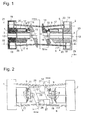
- Fig. 2 shows a side view of the hydraulic machine according to a second embodiment of the invention. Again, the jacket connecting the end walls 1, 2 is omitted in order to be able to show the interior of the machine.
- the several cylinder bores 7, 8 of each axial piston unit is shown on each axial piston unit 5, 6 only one.
- the control disk 13 carries two rod-shaped or rib-shaped supports 26, the tips of which slide slidably against contact blocks 27 of the control disk 14.
- the supports 26 and contact blocks 27 transmit the forces exerted by the pistons 9 of one of the axial piston units 5, 6 on the control disc 13 or 14 opposite them to the respective other control disc 14 or 13, so that the pressures of the axial piston units compensate each other and not the storage of the pivot axes 15, 16 am Housing or from the rods 17 must be collected.
- the tips of the posts 26 are slidable along the contact blocks 27 and remain in contact therewith when the control discs 13 are out of the in Fig. 2 shown, the strongest possible inclination ⁇ max or maximum possible amount of swallowing the axial piston units 5, 6 corresponding position in the in Fig. 3 be shown rotated position.
- the position of Fig. 3 is the inclination of the control discs 13, 14 only ⁇ min , and the tip of the upper support 26 is located directly on the border of a centered on the pivot axis 15 arcuate edge 28 of the upper contact block 27th
- the distance between the surfaces of the two control disks 13, 14 touched by the sliding shoes 11 is equal to the distance between them Swivel axes 15, 16 and regardless of the orientation of the discs, since the pivot axes 15, 16, the longitudinal axis 12 crossing along the respective piston 9 facing the surface of the control discs 13, 14 extend. Accordingly, the total amount of oil in the cylinder bores 7, 8 of the two axial piston units 5, 6 regardless of the orientation of the control discs 13, 14, and losses, on a, albeit small, compressibility of the circulating in the cylinder bores 7, 8 hydraulic oil are independent of the orientation of the control discs 13, 14.
- Fig. 5 shows one too Fig. 2 analogous view of a hydrostatic machine according to a third embodiment of the invention.
- the housing of the machine and the axial piston units 5, 6 are the same as in the previously considered embodiments and will not be described again.
- a plane perpendicular to the plane of the drawing, along the longitudinal axis 12 extending plane 29 divides the two control discs 13, 14 each in two halves, one of the associated axial piston unit 5 and 6 facing Half 13 'or 14' and a facing away from her half 13 "or 14".
- the pivot axes 15, 16 are offset parallel to the said plane 29 and are located respectively on the same side of the plane 29 as the axial piston units facing halves 13 'and 14' of the control discs.
- the pivot axes 15, 16 each intersect the longitudinal axis of a cylinder bore 7 and 8, whose (in the case of the axial piston unit 6 not shown) piston 9 is located at its top dead center. At this top dead center, the volume of the cylinder in question is practically zero, and it does not change depending on the orientation of the control disk 13 or 14. As a result, due to the compressibility of the hydraulic oil efficiency losses in this embodiment are negligible.
- Fig. 5 shows the control discs 13, 14 in a maximum inclined stop position, again with an inclined position of ⁇ max , in which the projection 32 is located at one end of the slot 31. Starting from this end, the course of the oblong hole 31 is initially dictated by the requirement that the two control disks 13, 14 should always pivot parallel to one another.
- Fig. 6 shows the control discs 13, 14 with the lowest possible inclination ⁇ min , which can reach the control disk 14.
- the projection 32 has not yet reached the opposite end of the slot 31 in this position.
- the portion 33 of the slot 31, which differs from the in Fig. 6 shown position of the projection 32 extends to the opposite end of the slot 31, is a circular arc whose center coincides with the pivot axis 15.
- the control disk 14 no longer follows a pivoting movement of the control disk 13, when this over the in Fig. 6 shown position strives to zero position.
Landscapes
- Engineering & Computer Science (AREA)
- Mechanical Engineering (AREA)
- General Engineering & Computer Science (AREA)
- Chemical & Material Sciences (AREA)
- Combustion & Propulsion (AREA)
- Reciprocating Pumps (AREA)
Applications Claiming Priority (1)
| Application Number | Priority Date | Filing Date | Title |
|---|---|---|---|
| DE201010021708 DE102010021708A1 (de) | 2010-05-27 | 2010-05-27 | Hydrostatische Maschine |
Publications (3)
| Publication Number | Publication Date |
|---|---|
| EP2390497A2 true EP2390497A2 (fr) | 2011-11-30 |
| EP2390497A3 EP2390497A3 (fr) | 2014-07-30 |
| EP2390497B1 EP2390497B1 (fr) | 2019-07-10 |
Family
ID=44484151
Family Applications (1)
| Application Number | Title | Priority Date | Filing Date |
|---|---|---|---|
| EP11004291.8A Active EP2390497B1 (fr) | 2010-05-27 | 2011-05-25 | Machine hydrostatique |
Country Status (4)
| Country | Link |
|---|---|
| US (1) | US9074586B2 (fr) |
| EP (1) | EP2390497B1 (fr) |
| CN (1) | CN102261316B (fr) |
| DE (1) | DE102010021708A1 (fr) |
Families Citing this family (3)
| Publication number | Priority date | Publication date | Assignee | Title |
|---|---|---|---|---|
| CN102434415B (zh) * | 2011-12-02 | 2014-09-03 | 浙江大学 | 一种基于串联泵转位角的低噪音轴向柱塞泵 |
| DE102014211664A1 (de) * | 2014-06-18 | 2015-12-24 | Zf Friedrichshafen Ag | Anordnung mit mehreren Axialkolbenmaschinen |
| EP4183936B1 (fr) * | 2021-11-22 | 2024-06-12 | Nabtesco Corporation | Dispositif d'entraînement et engin de chantier |
Citations (1)
| Publication number | Priority date | Publication date | Assignee | Title |
|---|---|---|---|---|
| DE102007022022A1 (de) | 2007-05-08 | 2008-11-13 | Claas Selbstfahrende Erntemaschinen Gmbh | Hydrostatische Maschine und diese verwendender Wandler |
Family Cites Families (13)
| Publication number | Priority date | Publication date | Assignee | Title |
|---|---|---|---|---|
| US3126707A (en) * | 1964-03-31 | Hydrostatic transmission | ||
| GB663648A (en) * | 1948-11-02 | 1951-12-27 | Richard Wagner Hautzenroeder | Improvements in or relating to a fluid displacement device |
| US2957462A (en) * | 1957-12-17 | 1960-10-25 | Clark Charles William | Internal combustion engines of the swash or wobble plate type |
| US3213619A (en) * | 1964-04-22 | 1965-10-26 | Ford Motor Co | Hydrostatic transmission |
| JPS55153872A (en) * | 1979-05-16 | 1980-12-01 | Honda Motor Co Ltd | Swash plate type hydraulic cylinder device |
| US5531072A (en) * | 1995-03-31 | 1996-07-02 | Martin Marietta Corporation | Continuously variable hydrostatic transmission having swashplate-mounted cylinder blocks |
| JPWO2005024233A1 (ja) * | 2003-09-02 | 2006-11-02 | 株式会社豊田自動織機 | 容量可変型斜板式圧縮機 |
| US7021904B2 (en) * | 2003-09-29 | 2006-04-04 | Kayaba Industry Co., Ltd. | Swash plate type hydraulic pump or motor |
| US20050238501A1 (en) * | 2004-04-26 | 2005-10-27 | Brailovskiy Aleksandr M | Revolving yoke load-sensitive displacement-varying mechanism for axial piston hydraulic pump |
| EP1770260A1 (fr) * | 2005-09-23 | 2007-04-04 | Van Rossem, Gerrit-Jan | Moteur à combustion avec pistons alignés parallèlement à l'arbre d'entrainement |
| CN101415944B (zh) * | 2006-03-14 | 2010-12-22 | 朱荣辉 | 轴向柱塞泵或马达 |
| JP5225597B2 (ja) * | 2007-03-16 | 2013-07-03 | カヤバ工業株式会社 | 対向式斜板型ピストンポンプ・モータ |
| DE102007049389A1 (de) * | 2007-10-15 | 2009-04-16 | Linde Material Handling Gmbh | Axialkolbenmaschine in Schrägscheibenbauweise |
-
2010
- 2010-05-27 DE DE201010021708 patent/DE102010021708A1/de not_active Withdrawn
-
2011
- 2011-05-25 EP EP11004291.8A patent/EP2390497B1/fr active Active
- 2011-05-25 US US13/115,312 patent/US9074586B2/en not_active Expired - Fee Related
- 2011-05-27 CN CN201110146953.5A patent/CN102261316B/zh active Active
Patent Citations (1)
| Publication number | Priority date | Publication date | Assignee | Title |
|---|---|---|---|---|
| DE102007022022A1 (de) | 2007-05-08 | 2008-11-13 | Claas Selbstfahrende Erntemaschinen Gmbh | Hydrostatische Maschine und diese verwendender Wandler |
Also Published As
| Publication number | Publication date |
|---|---|
| CN102261316B (zh) | 2015-12-02 |
| EP2390497A3 (fr) | 2014-07-30 |
| US9074586B2 (en) | 2015-07-07 |
| US20110315006A1 (en) | 2011-12-29 |
| EP2390497B1 (fr) | 2019-07-10 |
| DE102010021708A1 (de) | 2011-12-01 |
| CN102261316A (zh) | 2011-11-30 |
Similar Documents
| Publication | Publication Date | Title |
|---|---|---|
| EP2999885B1 (fr) | Machine à piston axial du type à plateau en biais | |
| EP0162238B1 (fr) | Machine à pistons axiaux, en particulier pompe du type à plateau incliné | |
| DE102007048316B4 (de) | Hydraulische Axialkolbenmaschine | |
| EP1510269A1 (fr) | Presse radiale pour sertir des corps creux à symétrie de rotation | |
| WO2010108582A1 (fr) | Dispositif destiné à faire varier le rapport de compression dans un moteur à combustion interne | |
| EP2145105B1 (fr) | Machine à pistons axiaux | |
| DE102007022568A1 (de) | Niederhaltesegment | |
| DE102011105544A1 (de) | Hydraulische Axialkolbenmaschine | |
| DE102020211284A1 (de) | Hydrostatische Axialkolbenmaschine in Schrägscheibenbauweise | |
| DE102007033008A1 (de) | Hydrostatisches Getriebe mit zwei Axialkolbentriebwerken | |
| EP2390497B1 (fr) | Machine hydrostatique | |
| DE3725525A1 (de) | Verstellbare axialkolbenmaschine in schraegachsenbauweise | |
| EP2010789A1 (fr) | Dispositif d'entrainement lineaire hydraulique | |
| WO2015086336A1 (fr) | Machine à plateau oscillant, plateau oscillant et procédé d'équilibrage hydrostatique d'un raccordement d'élément de réglage d'une machine à plateau oscillant | |
| DE4125706C1 (fr) | ||
| WO2015086337A1 (fr) | Machine à plateau oscillant, plateau oscillant et procédé d'équilibrage hydrostatique d'un raccordement d'élément de réglage d'une machine à plateau oscillant et de réduction de la pression d'un fluide de travail au cours d'un processus d'inversion de marche de la machine à plateau oscillant | |
| DE1528405A1 (de) | Hydraulische Vorrichtung | |
| EP2861348B1 (fr) | Concasseur à mâchoires | |
| DE3627375C2 (fr) | ||
| DE102013008681A1 (de) | Axialkolbenpumpe in Schrägscheibenbauart | |
| WO2008034808A1 (fr) | pompe à piston radial | |
| DE102021212098A1 (de) | Gleitschuh für eine Axialkolbenmaschine und Axialkolbenmaschine damit | |
| DE102018218547A1 (de) | Hydrostatische Axialkolbenmaschine | |
| DE10226492B4 (de) | Axialkolbenmaschine mit verstellbarem Kolbenhub | |
| DE102018003207A1 (de) | Axialkolbenpumpe in Schrägscheibenbauart |
Legal Events
| Date | Code | Title | Description |
|---|---|---|---|
| 17P | Request for examination filed |
Effective date: 20110617 |
|
| AK | Designated contracting states |
Kind code of ref document: A2 Designated state(s): AL AT BE BG CH CY CZ DE DK EE ES FI FR GB GR HR HU IE IS IT LI LT LU LV MC MK MT NL NO PL PT RO RS SE SI SK SM TR |
|
| AX | Request for extension of the european patent |
Extension state: BA ME |
|
| PUAI | Public reference made under article 153(3) epc to a published international application that has entered the european phase |
Free format text: ORIGINAL CODE: 0009012 |
|
| PUAL | Search report despatched |
Free format text: ORIGINAL CODE: 0009013 |
|
| AK | Designated contracting states |
Kind code of ref document: A3 Designated state(s): AL AT BE BG CH CY CZ DE DK EE ES FI FR GB GR HR HU IE IS IT LI LT LU LV MC MK MT NL NO PL PT RO RS SE SI SK SM TR |
|
| AX | Request for extension of the european patent |
Extension state: BA ME |
|
| RIC1 | Information provided on ipc code assigned before grant |
Ipc: F03C 1/40 20060101ALI20140624BHEP Ipc: F04B 1/22 20060101ALI20140624BHEP Ipc: F04B 1/32 20060101ALI20140624BHEP Ipc: F03C 1/06 20060101AFI20140624BHEP |
|
| RAP1 | Party data changed (applicant data changed or rights of an application transferred) |
Owner name: CLAAS SELBSTFAHRENDE ERNTEMASCHINEN GMBH |
|
| GRAP | Despatch of communication of intention to grant a patent |
Free format text: ORIGINAL CODE: EPIDOSNIGR1 |
|
| STAA | Information on the status of an ep patent application or granted ep patent |
Free format text: STATUS: GRANT OF PATENT IS INTENDED |
|
| INTG | Intention to grant announced |
Effective date: 20190321 |
|
| GRAS | Grant fee paid |
Free format text: ORIGINAL CODE: EPIDOSNIGR3 |
|
| GRAA | (expected) grant |
Free format text: ORIGINAL CODE: 0009210 |
|
| STAA | Information on the status of an ep patent application or granted ep patent |
Free format text: STATUS: THE PATENT HAS BEEN GRANTED |
|
| AK | Designated contracting states |
Kind code of ref document: B1 Designated state(s): AL AT BE BG CH CY CZ DE DK EE ES FI FR GB GR HR HU IE IS IT LI LT LU LV MC MK MT NL NO PL PT RO RS SE SI SK SM TR |
|
| REG | Reference to a national code |
Ref country code: GB Ref legal event code: FG4D Free format text: NOT ENGLISH |
|
| REG | Reference to a national code |
Ref country code: CH Ref legal event code: EP Ref country code: AT Ref legal event code: REF Ref document number: 1153834 Country of ref document: AT Kind code of ref document: T Effective date: 20190715 |
|
| REG | Reference to a national code |
Ref country code: DE Ref legal event code: R096 Ref document number: 502011015888 Country of ref document: DE |
|
| REG | Reference to a national code |
Ref country code: IE Ref legal event code: FG4D Free format text: LANGUAGE OF EP DOCUMENT: GERMAN |
|
| REG | Reference to a national code |
Ref country code: NL Ref legal event code: MP Effective date: 20190710 |
|
| REG | Reference to a national code |
Ref country code: LT Ref legal event code: MG4D |
|
| PG25 | Lapsed in a contracting state [announced via postgrant information from national office to epo] |
Ref country code: BG Free format text: LAPSE BECAUSE OF FAILURE TO SUBMIT A TRANSLATION OF THE DESCRIPTION OR TO PAY THE FEE WITHIN THE PRESCRIBED TIME-LIMIT Effective date: 20191010 Ref country code: SE Free format text: LAPSE BECAUSE OF FAILURE TO SUBMIT A TRANSLATION OF THE DESCRIPTION OR TO PAY THE FEE WITHIN THE PRESCRIBED TIME-LIMIT Effective date: 20190710 Ref country code: NL Free format text: LAPSE BECAUSE OF FAILURE TO SUBMIT A TRANSLATION OF THE DESCRIPTION OR TO PAY THE FEE WITHIN THE PRESCRIBED TIME-LIMIT Effective date: 20190710 Ref country code: PT Free format text: LAPSE BECAUSE OF FAILURE TO SUBMIT A TRANSLATION OF THE DESCRIPTION OR TO PAY THE FEE WITHIN THE PRESCRIBED TIME-LIMIT Effective date: 20191111 Ref country code: HR Free format text: LAPSE BECAUSE OF FAILURE TO SUBMIT A TRANSLATION OF THE DESCRIPTION OR TO PAY THE FEE WITHIN THE PRESCRIBED TIME-LIMIT Effective date: 20190710 Ref country code: LT Free format text: LAPSE BECAUSE OF FAILURE TO SUBMIT A TRANSLATION OF THE DESCRIPTION OR TO PAY THE FEE WITHIN THE PRESCRIBED TIME-LIMIT Effective date: 20190710 Ref country code: FI Free format text: LAPSE BECAUSE OF FAILURE TO SUBMIT A TRANSLATION OF THE DESCRIPTION OR TO PAY THE FEE WITHIN THE PRESCRIBED TIME-LIMIT Effective date: 20190710 Ref country code: NO Free format text: LAPSE BECAUSE OF FAILURE TO SUBMIT A TRANSLATION OF THE DESCRIPTION OR TO PAY THE FEE WITHIN THE PRESCRIBED TIME-LIMIT Effective date: 20191010 |
|
| PG25 | Lapsed in a contracting state [announced via postgrant information from national office to epo] |
Ref country code: AL Free format text: LAPSE BECAUSE OF FAILURE TO SUBMIT A TRANSLATION OF THE DESCRIPTION OR TO PAY THE FEE WITHIN THE PRESCRIBED TIME-LIMIT Effective date: 20190710 Ref country code: ES Free format text: LAPSE BECAUSE OF FAILURE TO SUBMIT A TRANSLATION OF THE DESCRIPTION OR TO PAY THE FEE WITHIN THE PRESCRIBED TIME-LIMIT Effective date: 20190710 Ref country code: IS Free format text: LAPSE BECAUSE OF FAILURE TO SUBMIT A TRANSLATION OF THE DESCRIPTION OR TO PAY THE FEE WITHIN THE PRESCRIBED TIME-LIMIT Effective date: 20191110 Ref country code: LV Free format text: LAPSE BECAUSE OF FAILURE TO SUBMIT A TRANSLATION OF THE DESCRIPTION OR TO PAY THE FEE WITHIN THE PRESCRIBED TIME-LIMIT Effective date: 20190710 Ref country code: GR Free format text: LAPSE BECAUSE OF FAILURE TO SUBMIT A TRANSLATION OF THE DESCRIPTION OR TO PAY THE FEE WITHIN THE PRESCRIBED TIME-LIMIT Effective date: 20191011 Ref country code: RS Free format text: LAPSE BECAUSE OF FAILURE TO SUBMIT A TRANSLATION OF THE DESCRIPTION OR TO PAY THE FEE WITHIN THE PRESCRIBED TIME-LIMIT Effective date: 20190710 |
|
| PG25 | Lapsed in a contracting state [announced via postgrant information from national office to epo] |
Ref country code: TR Free format text: LAPSE BECAUSE OF FAILURE TO SUBMIT A TRANSLATION OF THE DESCRIPTION OR TO PAY THE FEE WITHIN THE PRESCRIBED TIME-LIMIT Effective date: 20190710 |
|
| PG25 | Lapsed in a contracting state [announced via postgrant information from national office to epo] |
Ref country code: RO Free format text: LAPSE BECAUSE OF FAILURE TO SUBMIT A TRANSLATION OF THE DESCRIPTION OR TO PAY THE FEE WITHIN THE PRESCRIBED TIME-LIMIT Effective date: 20190710 Ref country code: EE Free format text: LAPSE BECAUSE OF FAILURE TO SUBMIT A TRANSLATION OF THE DESCRIPTION OR TO PAY THE FEE WITHIN THE PRESCRIBED TIME-LIMIT Effective date: 20190710 Ref country code: PL Free format text: LAPSE BECAUSE OF FAILURE TO SUBMIT A TRANSLATION OF THE DESCRIPTION OR TO PAY THE FEE WITHIN THE PRESCRIBED TIME-LIMIT Effective date: 20190710 Ref country code: DK Free format text: LAPSE BECAUSE OF FAILURE TO SUBMIT A TRANSLATION OF THE DESCRIPTION OR TO PAY THE FEE WITHIN THE PRESCRIBED TIME-LIMIT Effective date: 20190710 |
|
| PG25 | Lapsed in a contracting state [announced via postgrant information from national office to epo] |
Ref country code: IS Free format text: LAPSE BECAUSE OF FAILURE TO SUBMIT A TRANSLATION OF THE DESCRIPTION OR TO PAY THE FEE WITHIN THE PRESCRIBED TIME-LIMIT Effective date: 20200224 Ref country code: SK Free format text: LAPSE BECAUSE OF FAILURE TO SUBMIT A TRANSLATION OF THE DESCRIPTION OR TO PAY THE FEE WITHIN THE PRESCRIBED TIME-LIMIT Effective date: 20190710 Ref country code: SM Free format text: LAPSE BECAUSE OF FAILURE TO SUBMIT A TRANSLATION OF THE DESCRIPTION OR TO PAY THE FEE WITHIN THE PRESCRIBED TIME-LIMIT Effective date: 20190710 Ref country code: CZ Free format text: LAPSE BECAUSE OF FAILURE TO SUBMIT A TRANSLATION OF THE DESCRIPTION OR TO PAY THE FEE WITHIN THE PRESCRIBED TIME-LIMIT Effective date: 20190710 |
|
| REG | Reference to a national code |
Ref country code: DE Ref legal event code: R097 Ref document number: 502011015888 Country of ref document: DE |
|
| PLBE | No opposition filed within time limit |
Free format text: ORIGINAL CODE: 0009261 |
|
| STAA | Information on the status of an ep patent application or granted ep patent |
Free format text: STATUS: NO OPPOSITION FILED WITHIN TIME LIMIT |
|
| PG2D | Information on lapse in contracting state deleted |
Ref country code: IS |
|
| 26N | No opposition filed |
Effective date: 20200603 |
|
| PG25 | Lapsed in a contracting state [announced via postgrant information from national office to epo] |
Ref country code: SI Free format text: LAPSE BECAUSE OF FAILURE TO SUBMIT A TRANSLATION OF THE DESCRIPTION OR TO PAY THE FEE WITHIN THE PRESCRIBED TIME-LIMIT Effective date: 20190710 |
|
| PG25 | Lapsed in a contracting state [announced via postgrant information from national office to epo] |
Ref country code: MC Free format text: LAPSE BECAUSE OF FAILURE TO SUBMIT A TRANSLATION OF THE DESCRIPTION OR TO PAY THE FEE WITHIN THE PRESCRIBED TIME-LIMIT Effective date: 20190710 Ref country code: LI Free format text: LAPSE BECAUSE OF NON-PAYMENT OF DUE FEES Effective date: 20200531 Ref country code: CH Free format text: LAPSE BECAUSE OF NON-PAYMENT OF DUE FEES Effective date: 20200531 |
|
| GBPC | Gb: european patent ceased through non-payment of renewal fee |
Effective date: 20200525 |
|
| PG25 | Lapsed in a contracting state [announced via postgrant information from national office to epo] |
Ref country code: LU Free format text: LAPSE BECAUSE OF NON-PAYMENT OF DUE FEES Effective date: 20200525 |
|
| PG25 | Lapsed in a contracting state [announced via postgrant information from national office to epo] |
Ref country code: IE Free format text: LAPSE BECAUSE OF NON-PAYMENT OF DUE FEES Effective date: 20200525 Ref country code: FR Free format text: LAPSE BECAUSE OF NON-PAYMENT OF DUE FEES Effective date: 20200531 Ref country code: GB Free format text: LAPSE BECAUSE OF NON-PAYMENT OF DUE FEES Effective date: 20200525 |
|
| REG | Reference to a national code |
Ref country code: AT Ref legal event code: MM01 Ref document number: 1153834 Country of ref document: AT Kind code of ref document: T Effective date: 20200525 |
|
| PG25 | Lapsed in a contracting state [announced via postgrant information from national office to epo] |
Ref country code: AT Free format text: LAPSE BECAUSE OF NON-PAYMENT OF DUE FEES Effective date: 20200525 |
|
| PG25 | Lapsed in a contracting state [announced via postgrant information from national office to epo] |
Ref country code: MT Free format text: LAPSE BECAUSE OF FAILURE TO SUBMIT A TRANSLATION OF THE DESCRIPTION OR TO PAY THE FEE WITHIN THE PRESCRIBED TIME-LIMIT Effective date: 20190710 Ref country code: CY Free format text: LAPSE BECAUSE OF FAILURE TO SUBMIT A TRANSLATION OF THE DESCRIPTION OR TO PAY THE FEE WITHIN THE PRESCRIBED TIME-LIMIT Effective date: 20190710 |
|
| PG25 | Lapsed in a contracting state [announced via postgrant information from national office to epo] |
Ref country code: MK Free format text: LAPSE BECAUSE OF FAILURE TO SUBMIT A TRANSLATION OF THE DESCRIPTION OR TO PAY THE FEE WITHIN THE PRESCRIBED TIME-LIMIT Effective date: 20190710 |
|
| P01 | Opt-out of the competence of the unified patent court (upc) registered |
Effective date: 20230515 |
|
| REG | Reference to a national code |
Ref country code: DE Ref legal event code: R084 Ref document number: 502011015888 Country of ref document: DE |
|
| PGFP | Annual fee paid to national office [announced via postgrant information from national office to epo] |
Ref country code: BE Payment date: 20250521 Year of fee payment: 15 Ref country code: IT Payment date: 20250527 Year of fee payment: 15 |
|
| PGFP | Annual fee paid to national office [announced via postgrant information from national office to epo] |
Ref country code: DE Payment date: 20250521 Year of fee payment: 15 |