EP2390727A2 - Bilderzeugungsvorrichtung - Google Patents
Bilderzeugungsvorrichtung Download PDFInfo
- Publication number
- EP2390727A2 EP2390727A2 EP11166667A EP11166667A EP2390727A2 EP 2390727 A2 EP2390727 A2 EP 2390727A2 EP 11166667 A EP11166667 A EP 11166667A EP 11166667 A EP11166667 A EP 11166667A EP 2390727 A2 EP2390727 A2 EP 2390727A2
- Authority
- EP
- European Patent Office
- Prior art keywords
- image forming
- image
- value
- humidity
- developing device
- Prior art date
- Legal status (The legal status is an assumption and is not a legal conclusion. Google has not performed a legal analysis and makes no representation as to the accuracy of the status listed.)
- Withdrawn
Links
- 230000015572 biosynthetic process Effects 0.000 claims abstract description 21
- 238000001514 detection method Methods 0.000 claims abstract description 8
- 239000000463 material Substances 0.000 claims description 15
- 238000003756 stirring Methods 0.000 claims description 8
- 238000012546 transfer Methods 0.000 description 43
- XLYOFNOQVPJJNP-UHFFFAOYSA-N water Substances O XLYOFNOQVPJJNP-UHFFFAOYSA-N 0.000 description 31
- 230000008859 change Effects 0.000 description 29
- 230000007613 environmental effect Effects 0.000 description 29
- 238000000034 method Methods 0.000 description 27
- 230000006870 function Effects 0.000 description 26
- 230000006399 behavior Effects 0.000 description 15
- 230000000875 corresponding effect Effects 0.000 description 15
- 238000012545 processing Methods 0.000 description 8
- 230000001276 controlling effect Effects 0.000 description 7
- 230000000694 effects Effects 0.000 description 7
- 230000014509 gene expression Effects 0.000 description 7
- 238000002474 experimental method Methods 0.000 description 6
- 239000010410 layer Substances 0.000 description 6
- 239000002245 particle Substances 0.000 description 6
- 239000003086 colorant Substances 0.000 description 5
- 238000005259 measurement Methods 0.000 description 5
- 229920005989 resin Polymers 0.000 description 5
- 239000011347 resin Substances 0.000 description 5
- 238000007796 conventional method Methods 0.000 description 4
- BGPVFRJUHWVFKM-UHFFFAOYSA-N N1=C2C=CC=CC2=[N+]([O-])C1(CC1)CCC21N=C1C=CC=CC1=[N+]2[O-] Chemical compound N1=C2C=CC=CC2=[N+]([O-])C1(CC1)CCC21N=C1C=CC=CC1=[N+]2[O-] BGPVFRJUHWVFKM-UHFFFAOYSA-N 0.000 description 3
- 238000013459 approach Methods 0.000 description 3
- 239000002344 surface layer Substances 0.000 description 3
- 230000009471 action Effects 0.000 description 2
- 239000003795 chemical substances by application Substances 0.000 description 2
- 238000004140 cleaning Methods 0.000 description 2
- 239000011248 coating agent Substances 0.000 description 2
- 238000000576 coating method Methods 0.000 description 2
- 238000012937 correction Methods 0.000 description 2
- 238000010586 diagram Methods 0.000 description 2
- 238000005192 partition Methods 0.000 description 2
- 238000006116 polymerization reaction Methods 0.000 description 2
- 230000000379 polymerizing effect Effects 0.000 description 2
- 239000000843 powder Substances 0.000 description 2
- 230000001105 regulatory effect Effects 0.000 description 2
- KXGFMDJXCMQABM-UHFFFAOYSA-N 2-methoxy-6-methylphenol Chemical compound [CH]OC1=CC=CC([CH])=C1O KXGFMDJXCMQABM-UHFFFAOYSA-N 0.000 description 1
- 239000004925 Acrylic resin Substances 0.000 description 1
- 229920000178 Acrylic resin Polymers 0.000 description 1
- 238000010521 absorption reaction Methods 0.000 description 1
- 239000000654 additive Substances 0.000 description 1
- 230000000996 additive effect Effects 0.000 description 1
- XAGFODPZIPBFFR-UHFFFAOYSA-N aluminium Chemical compound [Al] XAGFODPZIPBFFR-UHFFFAOYSA-N 0.000 description 1
- 229910052782 aluminium Inorganic materials 0.000 description 1
- 230000002238 attenuated effect Effects 0.000 description 1
- 230000033228 biological regulation Effects 0.000 description 1
- 238000004891 communication Methods 0.000 description 1
- 230000002596 correlated effect Effects 0.000 description 1
- 238000000151 deposition Methods 0.000 description 1
- 230000005684 electric field Effects 0.000 description 1
- 239000000284 extract Substances 0.000 description 1
- 238000010438 heat treatment Methods 0.000 description 1
- 230000010365 information processing Effects 0.000 description 1
- SZVJSHCCFOBDDC-UHFFFAOYSA-N iron(II,III) oxide Inorganic materials O=[Fe]O[Fe]O[Fe]=O SZVJSHCCFOBDDC-UHFFFAOYSA-N 0.000 description 1
- 238000004898 kneading Methods 0.000 description 1
- 239000000696 magnetic material Substances 0.000 description 1
- 239000006247 magnetic powder Substances 0.000 description 1
- 230000000873 masking effect Effects 0.000 description 1
- 239000011159 matrix material Substances 0.000 description 1
- 239000000203 mixture Substances 0.000 description 1
- 238000012986 modification Methods 0.000 description 1
- 230000004048 modification Effects 0.000 description 1
- 229920001568 phenolic resin Polymers 0.000 description 1
- 239000005011 phenolic resin Substances 0.000 description 1
- 229920000728 polyester Polymers 0.000 description 1
- 238000003825 pressing Methods 0.000 description 1
- 230000008569 process Effects 0.000 description 1
- 238000010298 pulverizing process Methods 0.000 description 1
- 229920002050 silicone resin Polymers 0.000 description 1
- 238000003860 storage Methods 0.000 description 1
- 230000001629 suppression Effects 0.000 description 1
- 238000010557 suspension polymerization reaction Methods 0.000 description 1
- 238000011144 upstream manufacturing Methods 0.000 description 1
- 229910000859 α-Fe Inorganic materials 0.000 description 1
Images




Classifications
-
- G—PHYSICS
- G03—PHOTOGRAPHY; CINEMATOGRAPHY; ANALOGOUS TECHNIQUES USING WAVES OTHER THAN OPTICAL WAVES; ELECTROGRAPHY; HOLOGRAPHY
- G03G—ELECTROGRAPHY; ELECTROPHOTOGRAPHY; MAGNETOGRAPHY
- G03G21/00—Arrangements not provided for by groups G03G13/00 - G03G19/00, e.g. cleaning, elimination of residual charge
- G03G21/20—Humidity or temperature control also ozone evacuation; Internal apparatus environment control
-
- G—PHYSICS
- G03—PHOTOGRAPHY; CINEMATOGRAPHY; ANALOGOUS TECHNIQUES USING WAVES OTHER THAN OPTICAL WAVES; ELECTROGRAPHY; HOLOGRAPHY
- G03G—ELECTROGRAPHY; ELECTROPHOTOGRAPHY; MAGNETOGRAPHY
- G03G15/00—Apparatus for electrographic processes using a charge pattern
- G03G15/06—Apparatus for electrographic processes using a charge pattern for developing
- G03G15/065—Arrangements for controlling the potential of the developing electrode
-
- G—PHYSICS
- G03—PHOTOGRAPHY; CINEMATOGRAPHY; ANALOGOUS TECHNIQUES USING WAVES OTHER THAN OPTICAL WAVES; ELECTROGRAPHY; HOLOGRAPHY
- G03G—ELECTROGRAPHY; ELECTROPHOTOGRAPHY; MAGNETOGRAPHY
- G03G15/00—Apparatus for electrographic processes using a charge pattern
- G03G15/14—Apparatus for electrographic processes using a charge pattern for transferring a pattern to a second base
- G03G15/16—Apparatus for electrographic processes using a charge pattern for transferring a pattern to a second base of a toner pattern, e.g. a powder pattern, e.g. magnetic transfer
-
- G—PHYSICS
- G03—PHOTOGRAPHY; CINEMATOGRAPHY; ANALOGOUS TECHNIQUES USING WAVES OTHER THAN OPTICAL WAVES; ELECTROGRAPHY; HOLOGRAPHY
- G03G—ELECTROGRAPHY; ELECTROPHOTOGRAPHY; MAGNETOGRAPHY
- G03G15/00—Apparatus for electrographic processes using a charge pattern
- G03G15/50—Machine control of apparatus for electrographic processes using a charge pattern, e.g. regulating differents parts of the machine, multimode copiers, microprocessor control
-
- G—PHYSICS
- G03—PHOTOGRAPHY; CINEMATOGRAPHY; ANALOGOUS TECHNIQUES USING WAVES OTHER THAN OPTICAL WAVES; ELECTROGRAPHY; HOLOGRAPHY
- G03G—ELECTROGRAPHY; ELECTROPHOTOGRAPHY; MAGNETOGRAPHY
- G03G21/00—Arrangements not provided for by groups G03G13/00 - G03G19/00, e.g. cleaning, elimination of residual charge
- G03G21/20—Humidity or temperature control also ozone evacuation; Internal apparatus environment control
- G03G21/203—Humidity
Definitions
- the present invention relates to an image forming apparatus of an electrophotographic type.
- a toner image is formed by depositing charged toner on an electrostatic latent image formed on an electrostatic photosensitive member and is transferred onto a transfer material to obtain a recording image.
- an operation of the image forming apparatus has been controlled depending on a relationship between ambient temperature and humidity of the image forming apparatus and a toner charge amount.
- Japanese Laid-Open Patent Application No. 2006-139140 describes a control method in which relative humidity in the apparatus is detected by a humidity detecting means and an image forming condition is changed on the basis of a detected value and a control method in which absolute humidity (absolute water content per unit volume) is detected and the image forming condition is changed on the basis of a detected value.
- Japanese Patent No. 2808108 discloses that an image forming condition is controlled by storing history of humidity in the neighborhood of a toner hopper or a developing device, obtaining an average of humidity values in a past certain period and by judging that whether or not a predetermined high-humidity state is continued for the certain period to estimate a current moisture absorption state.
- a principal object of the present invention is to provide an image forming apparatus capable of effecting image forming condition control with higher accuracy by taking into consideration a developer humidity control behavior during drive and stop of drive of a developing device.
- an image forming apparatus comprising:
- Figure 1 is a schematic sectional vie of an image forming apparatus 100 in this embodiment.
- the image forming apparatus 100 is a tandem-type laser beam printer capable of forming a full-color image by an electrophotographic image forming process.
- the image forming apparatus 100 includes first, second, third and fourth image forming portions 10Y, 10M, 10C and 10K for forming color images of yellow, cyan, magenta and black, respectively.
- drum cartridges 20Y, 20M, 20C and 20K for performing image forming operations of the respective color toner images are disposed.
- These four drum cartridges 20Y, 20M, 20C and 20K are disposed in parallel along a movement direction of an image transfer surface of an intermediary transfer belt 24. For example, during formation of a full-color image (in a color mode), the toner images formed by the respective drum cartridges 20Y, 20M, 20C and 20K are superposedly transferred onto the intermediary transfer belt 24 which is a toner image receiving member.
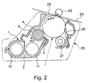
- FIG. 2 is a schematic sectional vie of the drum cartridge 20 of the image forming apparatus 100 in this embodiment.
- the toner image forming operation in the drum cartridge 20 will be described with reference to also Figure 2 .
- a surface of a drum type (cylindrical) electrophotographic photosensitive member as an image bearing to be rotationally driven in an arrow R1 direction i.e., a surface of a photosensitive drum 28 is electrically charged uniformly by a primary charger 21 as a charging means.
- the charged surface of the photosensitive drum 28 is exposed to laser light emitted from an exposure device (laser scanner) 22 as an exposure means in accordance with image information.
- an electrostatic latent image electrostatic image
- This electrostatic latent image is developed as a toner image by using a developer by a developing device 1 as a developing means.
- This toner image is transferred (primary-transferred), by a primary transfer roller 23 as a primary transfer means, onto an endless belt-like intermediary transfer belt 24 as an intermediary transfer member to be rotationally driven in an arrow R2 direction.
- a primary transfer bias which is a DC voltage of an opposite polarity to a normal charge polarity (negative in this embodiment) of the toner is applied from a primary transfer bias voltage source (not shown) as a primary transfer voltage applying means.
- the toner (primary transfer residual toner remaining on the photosensitive drum 28 after the toner images are transferred onto the intermediary transfer belt 24 is removed by a photosensitive member cleaner 26 as a photosensitive member cleaning means.
- the toner images transferred onto the intermediary transfer belt 24 are collectively transferred (secondary-transferred) onto a transfer material P, such as a recording sheet, which is a toner image receiving member by a secondary transfer roller 27 as a secondary transfer means.
- a secondary transfer bias which is a DC voltage of the opposite polarity to the normal charge polarity of the toner is applied from a secondary transfer bias voltage source (not shown) as a secondary transfer voltage applying means.
- the toner images transferred onto the transfer material P are fixed on the transfer material P by pressing and heating the transfer material P by a fixing device 25 as a fixing means.
- the transfer material P on which the toner images have been fixed is discharged to the outside of the image forming apparatus 100. Thus, a full-color recording image is obtained.
- the toner (secondary transfer residual toner) remaining on the intermediary transfer belt 24 after the toner images are transferred onto the transfer material P is removed by a belt cleaner 29 as an intermediary transfer member cleaning means.
- the toner image is formed only at an associated image forming portion 10 and may only be required to be transferred onto the transfer material P through the intermediary transfer belt 24.
- the photosensitive drum 28 in this embodiment is a negatively chargeable OPC (organic photoconductor) photosensitive member and is prepared by providing function layers principally formed of resin materials successively on a drum support, of aluminum, which has been grounded.
- the surface of the photosensitive drum 28 is uniformly charged by the primary charger 21.
- a potential at this uniformly charged portion is referred to as a white background portion potential or Vd (V).
- Vd white background portion potential
- Vd white background portion potential
- the negative electric charge on the surface of the photosensitive drum 28 is cancelled by a positive electric charge transported generated from the above-described function layer, so that the surface potential becomes a potential close to the ground potential.
- a potential at this portion where the electric charge is attenuated is referred to as an image portion potential or Vl (V).
- the primary charger 21 is a roller-shaped contact charger (charging roller) for charging the surface of the photosensitive drum 28 in contact with the surface of the photosensitive drum 28. At least during the formation of the electrostatic latent image on the photosensitive drum 28, to the primary charger 21, a predetermined charging bias is applied from a primary charging bias voltage source (not shown) as a primary charging voltage applying means. In this embodiment, a negative DC voltage is applied, as the primary charging bias, to the primary charging roller 21.
- a primary charging bias voltage source not shown
- a negative DC voltage is applied, as the primary charging bias, to the primary charging roller 21.
- the developing device 1 includes a developing container 2. At an opening of the developing container 2, a developing sleeve 3 as a developer carrying member is disposed.
- a two-component developing method is employed as a developing method.
- the developer a two-component developer in which negatively chargeable non-magnetic toner and a magnetic carrier are mixed is used.
- the non-magnetic toner toner which was prepared by kneading and polymerizing a colorant, a wax component and the like in a resin material principally of polyester and then by pulverizing and classifying a resultant product to obtain powder of about 7 ⁇ m in volume-average particle size was used.
- a carrier which was prepared by coating a silicone resin material on a surface layer of a ferrite core to have the volume-average particle size of 50 ⁇ m was used.
- a toner content in the developer (a weight ratio of the toner in the developer) in an initial state is 7 %.
- the developing sleeve 3 is constituted by a non-magnetic material and contains a stationary magnet 4 as a magnetic field generating means.
- the magnet 4 has a plurality of magnetic poles along its outer periphery. Further, during a developing operation, the developing sleeve 3 is rotated in an arrow R3 direction to hold the two-component developer, in a layer, contained in the developing container 2.
- the developer carried on the developing sleeve 3 forms an erected chain of a magnetic brush in a developing area.
- This magnetic brush is brought into a contact with or brought near to the surface of the photosensitive drum 28, so that the toner in the two-component developer is supplied to the photosensitive drum 28 depending on the electrostatic latent image formed on the surface of the photosensitive drum 28.
- the electrostatic latent image is developed as the toner image.
- a blade 5 for regulating a layer thickness of the developer by the action of the magnetic field in a cooperation with the magnet 4 at an upstream side of the developing area with respect to a rotational direction of the developing sleeve 3 is provided.
- the developer after the electrostatic (latent) image is developed on the photosensitive drum 28 is fed by the rotation of the developing sleeve 3 and is collected in a developing chamber (first developer accommodating chamber), which will be described later, of the developing container 2.
- the developing container 2 is roughly divided by a partition wall 15 into two chambers consisting of the developing chamber (first developer accommodating chamber) 11 (at a side close to the developing sleeve 3) and a stirring chamber (second developer accommodating chamber) 12 (at a side remote from the developing sleeve 3).
- Each of the developing chamber 11 and the stirring chamber 12 is extended along an axial direction of the developing sleeve 3 in this embodiment.
- the partition wall 15 does not reach each of inner side walls the developing container 2 at longitudinal end portions of the developing container 2, so that communication portions for permitting passing of the developer between the developing chamber 11 and the stirring chamber 12 are formed.
- the developing chamber 11 and the stirring chamber 12 are provided with a first screw 13 and a second screw 14, respectively, as a circulating and feeding member (stirring means) for circulating the developer between the developing chamber 11 and the stirring chamber 12.
- the developing sleeve 3, the first screw 13 and the second screw 14 are configured to be connected and driven by a gear train (not shown) and are rotated by receiving a driving force from a developing device driving gear (not shown). By rotation of these first and second screws 13 and 14, the developer is mixed and stirred while being circulated.
- the developing bias is in the form of a DC component Vdev (V) biased (superposed) with an AC component.
- V contrast potential
- Vcont contrast potential
- Vback V
- each of the voltage source (power source) for applying the primary charging bias to the primary charger 21 and the voltage source (power source) for applying the developing bias to the developing sleeve 3 is provided as two power sources for the first, second and third image forming portions 10Y, 10M and 10C and for the fourth image forming portion 10K.
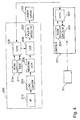
- FIG. 4 is a block diagram showing a system constitution of the image forming apparatus 100 in this embodiment.
- an image forming unit 200 inputs color image data as RGB image data, as desired, from an external device (not shown) such as an original scanner or a computer (information processing apparatus) through an external input interface (I/F) 213.
- An LOG converter 204 converts luminance (brightness) data of the inputted RGB image data into density data of respective colors or yellow (Y), magenta (M) and cyan (YMC image data) on the basis of a look-up table (LUT) constituted by data stored in ROM 210.
- LUT look-up table
- a masking/VCR portion 205 extracts component data for back (K) and subjects YMCK image data to matrix operation in order to correct color tubidity of a colorants for recording.
- a look-up table portion (LUT portion) 206 subjects the inputted YMCK image data to density correction every color by using ⁇ look-up table so as to match an ideal gradation characteristic of the image forming apparatus 100.
- the ⁇ look-up table is prepared on the basis of data developed on RAM 211 and contents thereof are set by a CPU 209.
- a pulse width modulating portion 207 outputs a pulse signal with a pulse width corresponding to a level of the image data (image signal) inputted from the LUT portion 206.
- a laser driver 102 drives the exposure device 22 to irradiate the surface of the photosensitive drum 28 with laser light, so that the electrostatic latent image is formed on the photosensitive drum 28.
- an operation of an apparatus main assembly A of the image forming apparatus 100 is collectively effected by a main assembly controller 301, inclusive of image forming condition control which will be described later.
- the main assembly controller 301 operates with a CPU 302, as a basic portion, which is provided therein.
- the CPU 302 controls respective portions of the apparatus by effecting computing (processing) in accordance with a program and data stored in ROM 304 and a data memory holding means (data memory) 303. Further, the CPU 302 of the main assembly controller 301 cooperates with the CPU 209 on the image forming unit side through an interface.
- the data memory 303 is, as described later, a storing means for storing environmental information and time information relating to the environmental information based on a measurement result of a temperature/humidity sensor 51.
- the CPU 302 functions, as described later, as a control means for controlling the image forming condition on the basis of a plurality of pieces of environmental information and pieces of time information relating to the pieces of the environmental information which are based on the measurement result of the temperature/humidity sensor 51 and on the basis of information relating to a driving state of the developing device 1.
- the temperature/humidity sensor 51 for measuring ambient temperature and humidity of the image forming apparatus 100 is provided as an environment detecting means (environment sensor). Further, as will be specifically described later, the image forming condition is determined by effecting processing by the CPU 302 on the basis of a detection result or the like of the temperature/humidity sensor 51.
- the present inventor conducted the following experiment. That is, a plurality of small-sized temperature/humidity sensors ("SHT 15", mfd. by Sensiron AG, Switzerland) were disposed at portions in a developing container of a drum cartridge of a laser beam printer ("LBP 5900", mfd. by Canon K.K.) so as to be contacted to or buried in the developer. Then, a behavior of a change in humidity measured by the temperature/humidity sensors was checked in detail.
- SHT 15 small-sized temperature/humidity sensors
- LBP 5900 laser beam printer
- the present invention is not applied but basic mechanical and electrical constitutions of the laser beam printer are identical to those of the image forming apparatus in this embodiment.
- a humidity control speed of the developer largely varies depending on a position of the developer. Specifically, the developer coated with a thin layer on the developing sleeve is quickly (in units of several tens of seconds) humidity-controlled. Further, a surface layer of the developer in the developing container is also relatively quickly (in units of several minutes) humidity-controlled. An area, of the developer in the developing container, confined inside the developer is slowly humidity-controlled in several tens of minutes to several hours.
- the "humidity control speed” is expressed by a time constant when a change curve of the measured humidity of the developer is approximately by an exponential function.
- the humidity of the developer in the developing container exhibits the following behavior. That is, when the developing device is not driven, the developer on the developing sleeve and the surface layer of the developer in the developing container are humidity-controlled but the inside of the developer in the developing container is not readily humidity-controlled. When drive of the developing device is started, the developer is successively humidity-controlled quickly by passing through the surface of the developer on the developing sleeve and in the developing container.
- one of objects in this embodiment is to effect the control with high accuracy by accurately grasp the developer humidity control behavior during the drive and stop of the drive of the developing device. Further, as a result, satisfaction of the high required level regulating the stability of the density and color in recent years is also one of the objects in this embodiment.
- the most simple conventional control method of the image forming condition is a method in which at least one of Vcont, Vback and ⁇ look-up table is controlled correspondingly to an output of the temperature/humidity sensor.
- a time until a function member such as the developer is adapted to the ambient humidity of the image forming apparatus is not taken into consideration. For this reason, as described in Japanese Patent No. 2808108 , the method in which the current image forming condition is controlled by using environmental history information.
- ABS absolute water content value
- the value ABS is obtained by calculation from the following data in the main assembly controller 301.
- current absolute water content data ABSn which are obtained from values of current temperature (°C) and relative humidity (%) which were measured by the temperature/humidity sensor 51, and current time data tn (year, month, day and hour, minute, second). These data are updated and stored in the data memory 303 of the main assembly controller 301.
- a battery is mounted and therefore can drive a time measuring means and a data memory holding means even when the power source of the apparatus main assembly A is not turned on.
- the value ABS may be obtained by collinear approximation in accordance with a predetermined slope obtained from two absolute water content data different in time or may also be obtained by approximately the behavior between the two absolute water content data different in time by using exponential function.
- the value ABS is obtained by the approximation by using the exponential function.
- a difference between tn and tm is calculated in units of 0.01 minute, and ⁇ which is a time constant of the exponential function is 240 minutes.
- ABS is regarded as the absolute water content of the inside ambience of the image forming apparatus 100, estimated from progression of ambient temperature and humidity at the periphery of the image forming apparatus, i.e., an absolute water content (predicted temperature and humidity information) of air contained in the developer in the developing container 2.
- the latest set value Vcont1 of Vcont which is one of the image forming conditions is calculated by making reference to a predetermined Vcont look-up table and is stored in the data memory 303 of the main assembly controller 301, so that the image forming apparatus 100 is placed in a print stand-by state (S904). Further, at the same time, the absolute water content data ABSm is updated to a newly calculated value ABS and is stored. A relationship between ABS and Vcont was obtained in advance by an experiment and has been stored, as a look-up table, in the ROM 304 of the main assembly controller 301.
- the reason why the history of the AWC is used as the environmental history information in this embodiment is that the toner charge amount of the two-component developer used in this embodiment is highly correlated with the absolute water content compared with the relative humidity.
- the absolute water content at the inside of the image forming apparatus 100 is estimated.
- This estimated absolute water content at the inside of the image forming apparatus 100 is regarded as the absolute water content of air contained in the developer at the inside of the developing container 2.
- a current developing characteristic of the developer is determined.
- the value of Vcont as the image forming condition is determined.
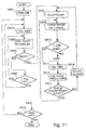
- Figure 5 is a flow chart of control in this specific example.
- a power source of an apparatus main assembly A is turned on (S101).
- the stop of drive of the developing device 1 or the drive of the developing device 1 as described later can be detected by checking an operation state of a driving means for transmitting a driving force to the developing device 1.
- the operation state such as an ON/OFF state of a driving motor or an ON/OFF state of a driving connection device (clutch) may be checked.
- ABS absolute water content value
- the value ABS is obtained by calculation from the following data in the main assembly controller 301.
- absolute water content data ABSm which have been stored immediately before the calculation, and time data tm (year, month, day and hour, minute, second) when the data ABSm is obtained.
- current absolute water content data ABSn which are obtained from values of current temperature (°C) and relative humidity (%) which were measured by the temperature/humidity sensor 51, and current time data tn (year, month, day and hour, minute, second). These data are updated and stored in the data memory 303 of the main assembly controller 301.
- a battery is mounted and therefore can drive a time measuring means and a data memory holding means even when the power source of the apparatus main assembly A is not turned on.
- ABS is obtained by approximately the behavior between the two absolute water content data different in time by using exponential function.
- a difference between tn and tm is calculated in units of 0.01 minute, and ⁇ w which is a time constant of the exponential function is 240 minutes.
- the latest set value Vcont 1 of Vcont which is one of the image forming conditions is calculated by making reference to a predetermined Vcont look-up table and is stored in the data memory 303 of the main assembly controller 301, so that the image forming apparatus 100 is placed in a print stand-by state (S104). Further, at the same time, the absolute water content data ABSm is updated to a newly calculated value ABS and is stored. A relationship between ABS and Vcont was obtained in advance by an experiment and has been stored, as a look-up table, in the ROM 304 of the main assembly controller 301.
- S105 whether or not a print instruction is provided is judged.
- a value of tn-tm is calculated and is judged as to whether or not the value is not less than 1 minute (S106).
- the procedure is returned to S103 in which the value ABS is calculated again.
- the value ABS is not calculated again and the procedure is returned to S104 in which the image forming apparatus is placed in a print stand-by state.
- values of high-voltage biases to be applied to the primary charger 21 and the developing sleeve 3 are set so that the value of Vcont equals to the value of Vcont 1 (S107). Then, at this setting, image formation for one page is effected (S108).
- ABS g / m 3 ABSm - ABSn x exp - tn - tm / ⁇ p + ABSn
- a difference between tn and tm is calculated in units of 0.01 minute, and ⁇ p which is a time constant of the exponential function is 5 minutes.
- a value of Vcont2 corresponding to the newly calculated value ABS is calculated (S112). Further, at the same time, the absolute water content data ABSm stored in the data memory 303 of the main assembly controller 301 is updated to the newly calculated value ABS and then is stored.
- the manner of obtaining the value ABS for obtaining Vcont2 is different and therefore in the case where the image forming apparatus, the value of Vcont2 used for the judgment in S113 and used as Vcont is different from that in the above-described reference example.
- the temperature/humidity environment measured by the temperature/humidity sensor 51 is changed to that different from the temperature/humidity environment indicated by the environmental information (ABSm) at a first time stored in the data memory 303.
- the CPU 302 which is the control means controls the image forming condition as described below when the image forming condition is changed to that different from the image forming condition corresponding to the temperature/humidity environment indicated by the environmental information at the first time after the temperature /humidity environment is changed as described above.
- the image forming condition is changed to different image forming conditions between the case where the developing device 1 is driven before the change of the image forming condition and the case where the developing device 1 is not driven before the change of the image forming condition.
- the drive of the developing device 1 includes at least one of an operation for feeding the developer inside the developing device 1 and an operation for stirring the developer inside the developing device 1 but in this embodiment, both of the operations are performed.
- the CPU 302 calculates the estimated temperature/humidity environment, to be reflected in the image forming condition control, at the inside of the image forming apparatus 100 by using the predetermined correlating equation obtained from the plurality of pieces of the environmental information on the basis of the measurement result of the temperature/humidity sensor 51 and from the time information (environmental history information) relating to the respective pieces of the environmental information. That is, the environmental information at the first time (ABSm) and the time information relating to the environmental information (ABSm), and the environmental information at the second time (ABSn) and the time information relating to the environmental information (ABSn) are applied to the predetermined correlating equation.
- the estimated temperature/humidity (ABS) different from the temperature/humidity environment indicated by the environmental information at the second time is calculated.
- the CPU 302 set the image forming condition at the second time as the image forming condition corresponding to this estimated temperature/humidity environment. Then, the CPU 302 changes the image forming condition after the change of the image forming condition by providing different predetermined correlating equations between the case where the developing device 1 is driven before the change of the image forming condition and the case where the developing device 1 is not driven before the change of the image forming condition.
- the CPU 302 controls the image forming condition, on the basis of the different exponential function approximation expressions in the case where the environment is changed, so as to be stepwisely changed to the image forming condition corresponding to the environment after the change of the image forming condition (the environmental information at the second time (ABSn)). Then, the CPU 302 is provided with the different exponential function approximation expressions corresponding to the case where the developing device is driven and the case where the developing device is not driven. As a result, it is possible to control the image forming condition so that a reaching time in which the image forming condition before the change in environment reaches the image forming condition corresponding to the environment after the change is shorter with a longer time of the drive of the developing device after the change in environment. Accordingly, the behavior of the humidity control of the developer (the phenomenon that the developer is adapted from the previously placed ambient state to the currently placed ambient state) can be controlled correspondingly to the developer humidity control behavior during the drive and stop of the drive of the developing device.
- the image forming condition control was explained by focusing the attention on that regarding one image forming portion 10.
- an example of an application manner of the image forming condition control regarding the respective image forming portions 10 will be described.
- the primary charging bias voltage sources and developing bias voltage sources for the first, second and third image forming portions 10Y, 10M and 10C are collectively controlled, and the primary charging bias voltage source and developing bias voltage source for the fourth image forming portion 10K are collectively controlled.
- the image forming condition control as shown in Figure 5 may be effected only for the fourth image forming portion 10K and there is no need to effect the image forming condition control as shown in Figure 5 for the first to third image forming portions 10Y, 10M and 10C.
- Figure 6 shows progression with time of the calculated value ABS.
- the progression of the value ABS in the reference example only shows a monotonical change (with a constant small slope in the graph).
- the progression of the value ABS in the specific example is largely changed in change rate per unit time (with an increasing slope in the graph) during the drive of the developing device 1 in the image forming operation.
- Figure 7 shows progression with time of the value Vcont set as the image forming condition.
- the value Vcont is changed so that the toner amount of the toner image, i.e., the image density is kept constant correspondingly to the progress of the humidity control of the developer in the developing device 1 by the drive of the developing device 1. That is, the progression of the value Vcont in the specific example is such that the change rate per unit time is largely changed (the slope in the graph is increased) during the drive of the developing device 1 in the image forming operation.
- the change in Vcont does not catch up with the humidity control speed of the developer and therefore the image density is gradually lowered.
- the progression of the value Vcont in the reference example shows only a monotonical change (with a constant small slope in the graph).
- the assumption that the time constant is adjusted so that the change in Vcont approaches that in the image forming condition control in the specific example is made. Even when such an adjustment is made, it would be considered that the adjustment is suitable only in the case where the image forming operation such that "the A4-sized image was outputted on 30 sheets (for 1 minute in LBP5900) and then the output was paused for 10 minutes" is repeated and therefore, this lacks versatility and thus is not practical.
- the condition after the change is closer to the condition corresponding to the temperature/humidity environment at the first time when the developing device 1 is not driven before the change than when the developing device 1 is driven before the change. That is, in the graph in Figure 7 , the value Vcont is closer to the value Vcont corresponding to the environment at the first time during start of the control in a period after the slope is increased by the drive of the developing device 1 than in a period before the slope is increased from that during the start of the control in which the developing device 1 is not driven.
- the change rate of the image forming condition is larger in the case where the developing device is not driven before the changes of the respective image forming conditions are made than in the case where the developing device is driven before the changes of the respective image forming conditions are made. That is, in the graph of Figure 7 , the change rate of the value Vcont is larger, in the period in which the developing device 1 is driven before the changes of the respective values Vcont and the slope is increased, than in the period in which the developing device 1 is not driven before the changes of the respective values Vcont and the slope is small.
- a polymerization toner produced by using a suspension polymerization was used as the toner.
- the polymerization toner has a volume-average particle size of 6 ⁇ m.
- a magnetic resin carrier prepared by dispersing and polymerizing magnetic powder such as magnetite powder in a phenolic resin to form particles and by surface-coating the particles with an acrylic resin was used.
- the magnetic carrier has the volume-average particle size of 35 ⁇ m.
- the toner charge amount of the two-component developer used in this embodiment has higher correlativity with the relative humidity than the absolute water content. This is presumably because the materials different from those in Embodiment 1 are used for the two-component developer. It would be considered that whether or not such a toner charge amount depends on what humidity index (the absolute water content, the relative humidity or an assumed intermediate index between the absolute water content and the relative humidity) varies depending on charge control agents to be added to the resin for the toner, and the resin for the carrier and on an external additive for the toner, and the like. Accordingly, in general, there is a need to check, through an experiment, whether or not the toner charge amount depends on what humidity index. In this embodiment, on the basis of the result of the experiment conducted in advance, a history of the relative humidity was used as the environmental history information in the image forming condition control.
- the image forming apparatus 100 independently includes the bias voltage sources (not shown) for generating the primary charging bias and the developing bias with respect to the first, second, third and fourth image forming portions 10Y, 10M, 10C and 10K.
- the description will be made by focusing attention on the image forming condition control with respect to one image forming portion 10.
- the image forming condition control density correction using ⁇ look-up tables ( ⁇ LUTs) is made in addition to the control of the value Vcont.
- the relative humidity values of RH which will be described later
- the value Vcont is set. A relationship between each environmental section and the value Vcont is stored in advance in the ROM 304 of the main assembly controller 301. Further, each of the divided 8 sections is further divided into 5 sub-sections.
- ⁇ look-up tables each determined from the value Vcont and the relative humidity, i.e., 40 ⁇ look-up tables for each of the 8 sections (160 ⁇ look-up tables in total for the four colors) are stored in the ROM 210.
- These ⁇ look-up tables are developed on the RAM 211 in accordance with an instruction from the CPU 201 and then are used.
- the ⁇ look-up table refers to a table, for determining 256 output levels with respect to 256 input levels, in which description that an output product of the image forming apparatus can obtain a desired density gradation level when laser light exposure with what pulse width is effected with respect to an inputted image signal has been made.
- Figure 8 is a flow chart of control in this embodiment.
- a power source of an apparatus main assembly A is turned on (S201).
- relative humidity value RH (%) used for determining a value of Vcont 1 described later is calculated (S203).
- the relative humidity is obtained as a ratio of current water vapor pressure to saturated water vapor pressure at a temperature and a humidity at measurement time. Incidentally, it may be considered that the pressure in an ambience in which the image forming apparatus 100 in this embodiment is used is substantially constant.
- the value RH is obtained by calculation, through exponential function approximation, from the following data in the main assembly controller 301.
- time data tm year, month, day and hour, minute, second
- current relative humidity data RHn measured by the temperature/humidity sensor 51
- current time data tn year, month, day and hour, minute, second.
- ABS is obtained by approximately the behavior between the two absolute water content data different in time by using exponential function.
- a difference between tn and tm is calculated in units of 0.01 minute, and ⁇ w which is a time constant of the exponential function is 240 minutes.
- the CPU 302 selects a value Vcont1 in the environmental section depending on the value RH. Further, via the CPU 302, the CPU 209 selects the ⁇ look-up table, from the 5 look-up tables in the associated environmental section, depending on the value RH and develops data of the selected ⁇ look-up table on the RAM 211, so that the image forming apparatus 100 is placed in a print stand-by state (S204). Further, at the same time, the relative humidity data RHm is updated to a newly calculated value RH and is stored. As a result, even when the value Vcont is roughly changed, tone gradation of the output image is kept by finely changing the ⁇ look-up table.
- S205 whether or not a print instruction is provided is judged (S205).
- a value of tn-tm is calculated and is judged as to whether or not the value is not less than 1 minute (S206).
- the procedure is returned to S203 in which the value RH is calculated again.
- the value RH is not calculated again and the procedure is returned to S204 in which the image forming apparatus is placed in a print stand-by state.
- values of high-voltage biases to be applied to the primary charger 21 and the developing sleeve 3 are set so that the value of Vcont equals to the value of Vcont 1 (S207). Then, at this setting of the value Vcont, the exposure by the exposure device 22 is effected on the basis of the ⁇ look-up table selected as described above, so that image formation for one page is effected (S208).
- a difference between tn and tm is calculated in units of 0.01 minute, and ⁇ p which is a time constant of the exponential function is 5 minutes.
- the relative humidity data RHm stored in the data memory 303 of the main assembly controller 301 is updated to the newly calculated value RH and then is stored.
- Vcont1 is judged (S213).
- the value Vcont2 is judged as being equal to the value Vcont1 in S213, the value of Vcont is kept at Vcont1 and the ⁇ look-up table based on the newly calculated value RH is selected (S214), and the procedure is returned to S208 in which subsequent image formation is effected.
- the value Vcont2 is judged as being changed from the value Vcont1 in S213, the value of Vcont1 is replaced with the value Vcont2 (S215), and the ⁇ look-up table based on the newly calculated value RH is selected (S216). Then, the procedure is returned to S207 in which the high-voltage bias values are set again so that the value of Vcont equals to the newly replaced value of Vcont1.
- the value Vcont in each environmental section was fixed at a predetermined value.
- the value Vcont may also be calculated by complementing an intermediate value of each value Vcont depending on the value RH. In this case, whether or not the change in Vcont exceeds a certain value may be checked in a step corresponding to S213.
- the plurality of ⁇ look-up tables in the respective environmental sections were prepared and were selectively used. However, in order to reduce the amount of storage of the ROM, a single ⁇ look-up table is prepared for the respective environmental sections and may also be changed by performing multiplication of a predetermined ratio or by adjusting a difference.
- Embodiment 1 similarly as in Embodiment 1, it is possible to effect the control with high accuracy by accurately grasping the developer humidity control behavior during the drive and stop of the drive of the developing device. As a result, it is possible to meet the high required level in recent years with respect to the stability of density and color.
- the drive of the developing sleeve 3 and the drive of the first and second screws 13 and 14 are independent from each other, so that the developing sleeve 3 and the first and second screws 13 and 14 can be independently actuated. Then, when the power source of the apparatus main assembly A is turned on, whether or not the value ABSn calculated from the detection result of the temperature/humidity sensor 51 at the time when the power source is turned on is changed by a predetermined value or more with respect to the value ABSm stored at the time of the last turning-off of the power source of the apparatus main assembly A is judged when the power source of the apparatus main assembly A is turned on.
- the developer inside the developing container 2 is stirred by rotating only the first and second screws 13 and 14 without rotating the developing sleeve 3, so that the ambient humidity at the periphery of the developer is mixed with that at the periphery of the image forming apparatus 100.
- the reason why the developing sleeve 3 is not rotated is that stress exerted on the developer by layer thickness regulation is alleviated as much as possible.
- FIG 9 shows a flow chart of the control in this embodiment. Incidentally, the operations identical to those in the steps in the flow chart of Figure 3 are represented by the same step numbers.
- the power source of the apparatus main assembly A is turned on (S101).
- the value ABSn is calculated (S301).
- an absolute value of the difference (ABSm-ABSn) is judged as to whether or not the absolute value is 5 (g/m 3 ) or less (S302).
- the procedure goes to S102 and subsequent processing is performed in the same manner as in S102 to S115 in Figure 5 .
- an operation in the screw drive mode (in which only the first and second screws 13 and 14 are rotated without rotating the developing sleeve 3) is executed for 1 minute (S304).
- the value ABS is calculated (S305).
- the absolute water content data ABSm stored in the data memory 303 of the main assembly controller 301 is updated to the newly calculated value ABS and is stored.
- whether or not an absolute value of a difference between the newly calculated value ABS and the value ABSn calculated during the turning-on of the power source of the apparatus main assembly A is 5 (g/m 3 ) or less is judged (S306).
- the procedure goes to S102 and subsequent processing is performed in the same manner as in S102 to S115 in Figure 5 . Further, in the case where the absolute value is judged as being not 5 (g/m 3 ) or less, the procedure is returned to S304.
- the ambient humidity of the image forming apparatus 100 is, during the turning-on of the power source, largely different from that at the time of the last use, the ambient humidity of the developer can be quickly brought near to the current ambient humidity of the image forming apparatus 100, so that the resultant image density can be further stabilized.
- the primary transfer bias to be applied to the primary transfer roller 23 is also controlled.
- a primary transfer bias look-up table is stored in advance in the ROM 304 and at the same time as timing of reading from a Vcont look-up table, an optimum primary transfer bias (electric) current value is selected from the primary transfer bias look-up table. Then, the primary transfer bias is controlled so as to be equal to the selected primary transfer bias (electric) current value.
- the control of the current value may be effected by an electric circuit capable of constant-current control or may also be effected by measuring a current passing through a constant-voltage circuit in advance and then by controlling a voltage value so that the current can flow. As a result, it becomes possible to more properly meet a change in transfer characteristic due to the change in toner charge amount.
- a temperature sensor 52 is provided in the neighborhood of the drum cartridge.
- the two-component driver used in this embodiment is somewhat different in composition from that used in Embodiment 2 and therefore the charge amount of the toner depends on not only the relative humidity but also the temperature.
- the temperature in the neighborhood of the developer is actually measured by using the temperature sensor 52 and from its result and the estimated relative humidity value, the calculation of the value Vcont and the selection of the ⁇ look-up table are effected. That is, the image forming condition is determined by using the actually measured temperature data in addition to the result of the humidity estimation control. For that reason, the stability of the image density is further increased.
- the present invention is not limited to the constitution in which the temperature sensor 52 is disposed in the neighborhood of the drum cartridge but may also employ a constitution in which temperature sensors 52 are disposed at proper positions such as on outer walls of the developing containers 2 for the respective colors.
- the image forming condition controlled in accordance with the present invention was the developing contrast Vcont, the exposure amount of the exposure device or the transfer bias.
- the image forming condition to be changed includes at least one image formation parameter selected from the surface potential of the photosensitive member, the exposure amount of the exposure device, the DC component of the developing bias, the AC component of the developing bias, the transfer bias voltage, the transfer bias current and a difference between the DC component of the developing bias and the surface potential of the photosensitive member.
- the image density is adjusted by changing the AC component (amplitude, waveform, frequency or the like) of the developing bias depending on the measurement result of the temperature/humidity sensor.
- parameter values to be changed in the cases where the developing device is not driven and is driven are taken as Pw and Pp, respectively, these parameter values may preferably satisfy the following formula: 1.5 x Pw ⁇ Pp ⁇ 100 x Pw
- Examples of the parameter values Pw and Pp may include the developing contrast Vcont, the time constants at the time of obtaining the values ABS and RH and the exposure amount of the exposure device as the result of application of the ⁇ look-up table.
- the humidity control speed also varies depending on a ratio between the volume of the developer and the surface area of the developer, thus depending on the constitution of the developing device.
- Pp ⁇ 1.5 x Pw a difference in time constant between the cases where the developing device is driven and is not driven becomes small, so that the effect of the present invention becomes small.
- Pp > 100 x Pw the image forming condition control using the environmental history information when the developing device is not driven becomes excessively slow or that when the developing device is driven becomes excessively fast, thus being not preferable.
- the present invention it becomes possible to effect the image forming condition control with high accuracy by taking into consideration the developer humidity control behavior during the drive and stop of the drive of the developing device.
- An image forming apparatus including an image bearing member; a developing device for developing with toner an electrostatic latent image formed on the image bearing member; a humidity sensor for providing information on ambient humidity of said image forming apparatus; and a controller for controlling a parameter on a density of an image to be formed on a recording material on the basis of pieces of the information provided by the humidity sensor at different times.
- the controller is capable of controlling the parameter so that, when a first image forming job is ended at an ending time and then a second image forming job is executed after a lapse of a predetermined time from the ending time and in a period in which a detection result of the humidity sensor changes and then is constant, a difference between a first set value which is the parameter set during formation of a final image in a first image forming job and a second set value which is the parameter set during image formation on a first sheet in the second image forming job after the lapse of the predetermined time from the ending time, increases with an increase of proportion of a time in which the developing device is driven during the lapse of the predetermined time.
Landscapes
- Physics & Mathematics (AREA)
- General Physics & Mathematics (AREA)
- Engineering & Computer Science (AREA)
- Life Sciences & Earth Sciences (AREA)
- Atmospheric Sciences (AREA)
- Biodiversity & Conservation Biology (AREA)
- Ecology (AREA)
- Environmental & Geological Engineering (AREA)
- Environmental Sciences (AREA)
- Microelectronics & Electronic Packaging (AREA)
- Control Or Security For Electrophotography (AREA)
- Dry Development In Electrophotography (AREA)
Applications Claiming Priority (1)
| Application Number | Priority Date | Filing Date | Title |
|---|---|---|---|
| JP2010122133A JP5174086B2 (ja) | 2010-05-27 | 2010-05-27 | 画像形成装置 |
Publications (2)
| Publication Number | Publication Date |
|---|---|
| EP2390727A2 true EP2390727A2 (de) | 2011-11-30 |
| EP2390727A3 EP2390727A3 (de) | 2012-08-08 |
Family
ID=44342767
Family Applications (1)
| Application Number | Title | Priority Date | Filing Date |
|---|---|---|---|
| EP11166667A Withdrawn EP2390727A3 (de) | 2010-05-27 | 2011-05-19 | Bilderzeugungsvorrichtung |
Country Status (5)
| Country | Link |
|---|---|
| US (2) | US8666269B2 (de) |
| EP (1) | EP2390727A3 (de) |
| JP (1) | JP5174086B2 (de) |
| KR (1) | KR101342714B1 (de) |
| CN (2) | CN102262380A (de) |
Families Citing this family (16)
| Publication number | Priority date | Publication date | Assignee | Title |
|---|---|---|---|---|
| JP5743506B2 (ja) | 2010-11-30 | 2015-07-01 | キヤノン株式会社 | 画像形成装置 |
| DE102011056735B3 (de) * | 2011-12-21 | 2012-10-25 | OCé PRINTING SYSTEMS GMBH | Verfahren zum Steuern des Leistungsbedarfs eines digitalen Hochleistungsdrucksystems und Hochleistungsdrucksystem zum Ausführen dieses Verfahrens |
| JP2013145264A (ja) | 2012-01-13 | 2013-07-25 | Canon Inc | 画像形成装置 |
| JP5611267B2 (ja) * | 2012-04-25 | 2014-10-22 | 京セラドキュメントソリューションズ株式会社 | 現像装置及び画像形成装置 |
| JP2014170197A (ja) | 2013-03-05 | 2014-09-18 | Canon Inc | 画像形成装置 |
| JP6641701B2 (ja) * | 2014-03-14 | 2020-02-05 | 株式会社リコー | 雰囲気センサとその製造方法、及び印刷物の製造方法 |
| JP6507661B2 (ja) * | 2015-01-16 | 2019-05-08 | 富士ゼロックス株式会社 | 画像形成装置 |
| JP6635815B2 (ja) * | 2016-02-05 | 2020-01-29 | キヤノン株式会社 | 画像形成装置 |
| CN107436549B (zh) * | 2016-05-27 | 2020-08-25 | 佳能株式会社 | 图像形成装置 |
| JP2018155782A (ja) * | 2017-03-15 | 2018-10-04 | コニカミノルタ株式会社 | 制御装置、画像形成装置およびプログラム |
| JP6865109B2 (ja) * | 2017-05-31 | 2021-04-28 | 株式会社東芝 | 画像処理装置 |
| US10852692B1 (en) * | 2019-09-16 | 2020-12-01 | Toshiba Tec Kabushiki Kaisha | Image forming apparatus and image forming method |
| US10852682B1 (en) * | 2019-09-18 | 2020-12-01 | Toshiba Tec Kabushiki Kaisha | Image forming apparatus, fixing temperature determination method, and non-transitory computer readable medium |
| CN111170161B (zh) * | 2019-12-28 | 2021-06-18 | 贵州云腾未来科技有限公司 | 基于场景检测的模式设定系统 |
| US11226586B1 (en) * | 2020-09-24 | 2022-01-18 | Toshiba Tec Kabushiki Kaisha | Image forming apparatus and processing method |
| CN115494708A (zh) * | 2022-09-23 | 2022-12-20 | 珠海奔图电子有限公司 | 图像形成设备、图像形成设备的控制方法及装置 |
Citations (2)
| Publication number | Priority date | Publication date | Assignee | Title |
|---|---|---|---|---|
| JP2808108B2 (ja) | 1987-01-19 | 1998-10-08 | キヤノン株式会社 | 画像形成装置 |
| JP2006139140A (ja) | 2004-11-12 | 2006-06-01 | Canon Inc | 画像形成装置 |
Family Cites Families (10)
| Publication number | Priority date | Publication date | Assignee | Title |
|---|---|---|---|---|
| JPH0434563A (ja) * | 1990-05-31 | 1992-02-05 | Toshiba Corp | 画像形成装置 |
| JPH08146752A (ja) | 1994-11-24 | 1996-06-07 | Hitachi Ltd | 電子写真装置 |
| JP2000029295A (ja) * | 1998-07-14 | 2000-01-28 | Minolta Co Ltd | 画像形成装置 |
| JP2001147620A (ja) * | 1999-11-19 | 2001-05-29 | Canon Inc | 電子写真画像形成装置およびカートリッジ |
| JP2004264756A (ja) * | 2003-03-04 | 2004-09-24 | Canon Inc | 画像形成装置 |
| JP2005140917A (ja) | 2003-11-05 | 2005-06-02 | Sharp Corp | 現像装置,画像形成装置,現像方法 |
| JP2006189562A (ja) | 2005-01-05 | 2006-07-20 | Konica Minolta Business Technologies Inc | 画像形成装置 |
| JP2008029295A (ja) * | 2006-07-31 | 2008-02-14 | Iseki & Co Ltd | 脱穀装置 |
| JP2008131152A (ja) * | 2006-11-17 | 2008-06-05 | Fujitsu Media Device Kk | 弾性表面波デバイス |
| JP5006625B2 (ja) * | 2006-12-01 | 2012-08-22 | キヤノン株式会社 | 画像形成装置 |
-
2010
- 2010-05-27 JP JP2010122133A patent/JP5174086B2/ja not_active Expired - Fee Related
-
2011
- 2011-05-12 US US13/106,186 patent/US8666269B2/en not_active Expired - Fee Related
- 2011-05-19 EP EP11166667A patent/EP2390727A3/de not_active Withdrawn
- 2011-05-27 CN CN2011101393042A patent/CN102262380A/zh active Pending
- 2011-05-27 KR KR1020110050786A patent/KR101342714B1/ko not_active Expired - Fee Related
- 2011-05-27 CN CN201410038132.3A patent/CN103777489B/zh not_active Expired - Fee Related
-
2014
- 2014-01-08 US US14/150,088 patent/US9158273B2/en not_active Expired - Fee Related
Patent Citations (2)
| Publication number | Priority date | Publication date | Assignee | Title |
|---|---|---|---|---|
| JP2808108B2 (ja) | 1987-01-19 | 1998-10-08 | キヤノン株式会社 | 画像形成装置 |
| JP2006139140A (ja) | 2004-11-12 | 2006-06-01 | Canon Inc | 画像形成装置 |
Also Published As
| Publication number | Publication date |
|---|---|
| JP5174086B2 (ja) | 2013-04-03 |
| CN103777489A (zh) | 2014-05-07 |
| CN103777489B (zh) | 2017-10-03 |
| EP2390727A3 (de) | 2012-08-08 |
| CN102262380A (zh) | 2011-11-30 |
| JP2011248154A (ja) | 2011-12-08 |
| US20110293300A1 (en) | 2011-12-01 |
| KR20110130370A (ko) | 2011-12-05 |
| US9158273B2 (en) | 2015-10-13 |
| US20140119754A1 (en) | 2014-05-01 |
| US8666269B2 (en) | 2014-03-04 |
| KR101342714B1 (ko) | 2013-12-18 |
Similar Documents
| Publication | Publication Date | Title |
|---|---|---|
| US8666269B2 (en) | Image forming apparatus | |
| US8385754B2 (en) | Image forming apparatus featuring forced discharging of excessive developer | |
| EP1580615B1 (de) | Bilderzeugungsgerät zur Optimierung des Glanz eines auf Aufzeichnungsmaterial mit transparentem oder weissem Toner geformten Bildes | |
| US8582995B2 (en) | Image forming apparatus with image forming condition control feature based on difference in patch densities | |
| US9454109B2 (en) | Image forming apparatus controlling transfer conditions based on resistance of transfer member | |
| US10303103B2 (en) | Image forming apparatus | |
| US9057985B2 (en) | Image forming apparatus | |
| US20130251387A1 (en) | Image forming apparatus | |
| US20130183052A1 (en) | Image forming apparatus | |
| US9557683B2 (en) | Image forming apparatus with forced supply mode for forcedly supplying toner | |
| US9152114B2 (en) | Image forming apparatus | |
| US9280137B2 (en) | Image forming apparatus with development contrast control | |
| JP4650718B2 (ja) | 画像形成装置及び画像形成装置のトナー補給制御方法 | |
| JP2007036411A (ja) | 画像処理装置および画像処理方法 | |
| JP2000259059A (ja) | 画像形成装置及び画像形成方法 | |
| JP2024046314A (ja) | 画像形成装置、かぶりマージン決定方法およびかぶりマージン決定プログラム | |
| JPH08286441A (ja) | 電子写真プロセス制御装置 | |
| JP2023085891A (ja) | 画像形成装置 | |
| JP2006126821A (ja) | 画像形成装置 | |
| JP2012123099A (ja) | 画像形成装置 | |
| JP2013195987A (ja) | 画像形成装置 | |
| JP2010060660A (ja) | 画像形成装置 |
Legal Events
| Date | Code | Title | Description |
|---|---|---|---|
| AK | Designated contracting states |
Kind code of ref document: A2 Designated state(s): AL AT BE BG CH CY CZ DE DK EE ES FI FR GB GR HR HU IE IS IT LI LT LU LV MC MK MT NL NO PL PT RO RS SE SI SK SM TR |
|
| AX | Request for extension of the european patent |
Extension state: BA ME |
|
| PUAI | Public reference made under article 153(3) epc to a published international application that has entered the european phase |
Free format text: ORIGINAL CODE: 0009012 |
|
| PUAL | Search report despatched |
Free format text: ORIGINAL CODE: 0009013 |
|
| AK | Designated contracting states |
Kind code of ref document: A3 Designated state(s): AL AT BE BG CH CY CZ DE DK EE ES FI FR GB GR HR HU IE IS IT LI LT LU LV MC MK MT NL NO PL PT RO RS SE SI SK SM TR |
|
| AX | Request for extension of the european patent |
Extension state: BA ME |
|
| RIC1 | Information provided on ipc code assigned before grant |
Ipc: G03G 15/06 20060101ALI20120629BHEP Ipc: G03G 15/00 20060101AFI20120629BHEP |
|
| 17P | Request for examination filed |
Effective date: 20130208 |
|
| STAA | Information on the status of an ep patent application or granted ep patent |
Free format text: STATUS: THE APPLICATION HAS BEEN WITHDRAWN |
|
| 18W | Application withdrawn |
Effective date: 20180530 |