EP2390751B1 - Verfahren zur Verfolgung des maximalen Leistungspunkts, Fotovoltaiksystemsteuerung und Fotovoltaiksystem - Google Patents
Verfahren zur Verfolgung des maximalen Leistungspunkts, Fotovoltaiksystemsteuerung und Fotovoltaiksystem Download PDFInfo
- Publication number
- EP2390751B1 EP2390751B1 EP20100164393 EP10164393A EP2390751B1 EP 2390751 B1 EP2390751 B1 EP 2390751B1 EP 20100164393 EP20100164393 EP 20100164393 EP 10164393 A EP10164393 A EP 10164393A EP 2390751 B1 EP2390751 B1 EP 2390751B1
- Authority
- EP
- European Patent Office
- Prior art keywords
- voltage
- photovoltaic system
- power output
- value
- duty cycle
- Prior art date
- Legal status (The legal status is an assumption and is not a legal conclusion. Google has not performed a legal analysis and makes no representation as to the accuracy of the status listed.)
- Not-in-force
Links
- 238000000034 method Methods 0.000 title claims description 60
- 230000008859 change Effects 0.000 claims description 28
- 238000005259 measurement Methods 0.000 claims description 16
- 230000003247 decreasing effect Effects 0.000 claims description 9
- 230000007423 decrease Effects 0.000 claims description 5
- 238000004590 computer program Methods 0.000 claims description 4
- 230000006870 function Effects 0.000 claims description 4
- 230000000977 initiatory effect Effects 0.000 claims description 2
- 238000005070 sampling Methods 0.000 claims description 2
- 210000004027 cell Anatomy 0.000 description 11
- 238000005286 illumination Methods 0.000 description 10
- 230000008901 benefit Effects 0.000 description 5
- 230000009897 systematic effect Effects 0.000 description 5
- 238000003491 array Methods 0.000 description 4
- 238000001514 detection method Methods 0.000 description 4
- 230000008569 process Effects 0.000 description 3
- 238000013459 approach Methods 0.000 description 2
- 230000005611 electricity Effects 0.000 description 2
- 239000002803 fossil fuel Substances 0.000 description 2
- 238000012544 monitoring process Methods 0.000 description 2
- 230000009471 action Effects 0.000 description 1
- 238000006243 chemical reaction Methods 0.000 description 1
- 230000000052 comparative effect Effects 0.000 description 1
- 238000013461 design Methods 0.000 description 1
- 239000005431 greenhouse gas Substances 0.000 description 1
- 238000003306 harvesting Methods 0.000 description 1
- 210000001357 hemopoietic progenitor cell Anatomy 0.000 description 1
- 238000004519 manufacturing process Methods 0.000 description 1
- 239000000463 material Substances 0.000 description 1
- 238000001167 microscope projection photolithography Methods 0.000 description 1
- 230000002250 progressing effect Effects 0.000 description 1
- 238000013139 quantization Methods 0.000 description 1
- 230000009467 reduction Effects 0.000 description 1
- 238000011160 research Methods 0.000 description 1
- 238000004088 simulation Methods 0.000 description 1
- 238000010408 sweeping Methods 0.000 description 1
Images

Classifications
-
- G—PHYSICS
- G05—CONTROLLING; REGULATING
- G05F—SYSTEMS FOR REGULATING ELECTRIC OR MAGNETIC VARIABLES
- G05F1/00—Automatic systems in which deviations of an electric quantity from one or more predetermined values are detected at the output of the system and fed back to a device within the system to restore the detected quantity to its predetermined value or values, i.e. retroactive systems
- G05F1/66—Regulating electric power
- G05F1/67—Regulating electric power to the maximum power available from a generator, e.g. from solar cell
-
- Y—GENERAL TAGGING OF NEW TECHNOLOGICAL DEVELOPMENTS; GENERAL TAGGING OF CROSS-SECTIONAL TECHNOLOGIES SPANNING OVER SEVERAL SECTIONS OF THE IPC; TECHNICAL SUBJECTS COVERED BY FORMER USPC CROSS-REFERENCE ART COLLECTIONS [XRACs] AND DIGESTS
- Y02—TECHNOLOGIES OR APPLICATIONS FOR MITIGATION OR ADAPTATION AGAINST CLIMATE CHANGE
- Y02E—REDUCTION OF GREENHOUSE GAS [GHG] EMISSIONS, RELATED TO ENERGY GENERATION, TRANSMISSION OR DISTRIBUTION
- Y02E10/00—Energy generation through renewable energy sources
- Y02E10/50—Photovoltaic [PV] energy
- Y02E10/56—Power conversion systems, e.g. maximum power point trackers
Definitions
- the present invention relates to a method of tracking a maximum power point of a photovoltaic system comprising a circuit including a controller controlling a direct current (DC) voltage to DC voltage converter for converting an output current of the photovoltaic system.
- a direct current (DC) voltage to DC voltage converter for converting an output current of the photovoltaic system.
- the present invention further relates to a photovoltaic system controller implementing such a method.
- the present invention yet further relates to a photovoltaic system comprising such a photovoltaic system controller.
- renewable energy generation is attracting considerable attention for a number of reasons. Firstly, renewable energy is considered the preferred alternative to fossil fuel based energy generation in order to combat greenhouse gas emissions such as CO 2 , which are held responsible for the changes to global climates. Secondly, with supplies of fossil fuels, and in particular oil, expected to run out in the foreseeable future, alternative energy supplies must be found for future generations.
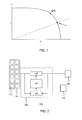
- FIG. 1 in which the I-V curve (solid line) of the photovoltaic system at a given irradiation intensity is depicted together with such a load (dashed line).
- the system's operating point is determined by the intersection of the I-V curve with the load profile.
- the operating point is at a lower power point instead of at the maximum power point (MPP), which is the point on the I-V curve where the product of the operating voltage and current, i.e. the output power is at a maximum.
- MPP maximum power point
- photovoltaic systems typically comprise a photovoltaic system controller that matches the load or impedance of the circuit connected to the photovoltaic cells in order to ensure that the photovoltaic system operates at the maximum power point by means of controlling the duty cycle of a DC voltage -DC voltage converter that converts the direct current voltage generated by photovoltaic cells into a further voltage.
- a photovoltaic system controller that matches the load or impedance of the circuit connected to the photovoltaic cells in order to ensure that the photovoltaic system operates at the maximum power point by means of controlling the duty cycle of a DC voltage -DC voltage converter that converts the direct current voltage generated by photovoltaic cells into a further voltage.
- a drawback of the P&O algorithm is that its convergence to the maximum power point can be slow, and that shifts in the maximum power point during execution of the algorithm can cause the power point of the photovoltaic system to oscillate around the maximum power point, or even diverge from the maximum power point.
- INC incremental conductance
- MPP tracking is the constant voltage algorithm, which is based on the realization that the ratio between the maximum power voltage of the photovoltaic cell array and the open-circuit voltage is more or less constant for different I-V curves of the photovoltaic system.
- a drawback of this algorithm is that the MPP voltage is not always a fixed percentage of the open circuit voltage, as it depends on manufacturing process, quality of materials and other factors, and therefore requires frequent measurement of the open-circuit voltage in order to accurately track MPP, as the MPP can vary quite often due to changes in e.g. irradiance, temperature and partial shadowing.
- the battery of the photovoltaic system cannot be charged, i.e. the power output of the photovoltaic cell array is lost, thereby reducing the efficiency of the photovoltaic system.
- the present invention seeks to provide an improved method of tracking the maximum power point of a photovoltaic system.
- the present invention further seeks to provide a photovoltaic system controller implementing the improved method.
- the present invention yet further seeks to provide a photovoltaic system including such a photovoltaic system controller.
- the present invention yet further seeks to provide a computer program product for implementing the improved method of the present invention.
- a method of tracking a maximum power point of a photovoltaic system comprising a circuit including a controller controlling a DC voltage -DC voltage converter for converting an output current of the photovoltaic system, the controller further comprising a memory, the method comprising measuring a first value of a photovoltaic system voltage at an initial maximum power point; storing said first value in said memory; periodically sampling a power output level of said photovoltaic system, and upon detecting a change in said power output level exceeding a first threshold, reading the first value from the memory and adjusting a duty cycle of the DC voltage -DC voltage converter until the circuit voltage matches said first value; the method further comprising fine-tuning the duty cycle of the DC voltage - DC voltage converter to a further maximum power point following detecting a change in said power output level exceeding a first threshold.
- This MPP tracking method of the present invention has the advantage that can more rapidly converge to an adjusted MPP compared to P&O and INC methods for large changes in the illumination conditions of the photovoltaic system, whereas compared to the CV method, an improved efficiency is achieved because the tracking of the variation in power output does not require the frequent measurement of the open circuit voltage of the photovoltaic system.
- the method further comprises, upon detecting a change in said power output level exceeding a first threshold, determining the actual value of the photovoltaic system voltage and comparing said actual value with the first value, wherein the execution of the steps of reading the first value from the memory and adjusting a duty cycle of the DC voltage - DC voltage converter until the circuit voltage matches said first value is conditional upon a difference between the actual value with the first value exceeding a further threshold.
- detecting said change in power level comprises detecting said change as a function of the delay between subsequent samples.
- dP/dt differential power output
- said fine-tuning comprises tracking the power output of the photovoltaic system following said adjusting step; and adjusting the power output of the photovoltaic system by alternately increasing and decreasing the duty cycle of the DC voltage -DC voltage converter until a further maximum power point of the photovoltaic system is reached.
- the step of increasing the duty cycle of the DC voltage - DC voltage converter comprises stepwise increasing the duty cycle of the DC voltage - DC voltage converter in a number of steps each having a defined step size and measuring the power output of the photovoltaic system after each step until the power output measured after the penultimate step exceeds the power output measured after the last step;
- the step of decreasing the duty cycle of the DC voltage - DC voltage converter comprises stepwise decreasing the duty cycle of the DC voltage - DC voltage converter in a number of steps each having a defined step size and measuring the power output of the photovoltaic system after each step until the power output measured after the penultimate step exceeds the power output measured after the last step; and reducing the defined step size following the termination of a stepwise increasing or stepwise decreasing of said duty cycle.
- the total number of alternate increases and decreases of the duty cycle is 3, as it has been found that three cycles, e.g. increase-decrease-increase or decrease-increase-decrease is sufficient to converge at the MPP, especially when the step size is reduced for each subsequent step sequence.
- the method may further comprise measuring a second value of the circuit voltage at said further maximum power point; and storing said second value in said memory.
- This second value may be used in a next MPP tracking step, where it may provide a more accurate estimation than the first value, especially when both changes in power output were in the same direction.
- the step of tracking the power output of the photovoltaic system following said adjusting step comprises performing a two-point power output measurement for determining a differential power output of the photovoltaic system; and initiating said adjusting step if the differential power output lies below a second threshold.
- the method may further comprise performing a two-point power output measurement for determining a differential power output of the photovoltaic system during said fine-tuning; and restarting said fine-tuning upon said determined differential power output exceeding a third threshold.
- a fine-tuning process is aborted and restarted if during the fine-tuning a substantial shift in the power output, indicative of a change in illumination levels, is detected. This prevents the MPP tracking to diverge from the MPP due to such sudden changes in illumination levels, which shift the MPP away from its previous location.
- a photovoltaic system controller comprising a DC voltage -DC voltage converter for converting the direct current from a photovoltaic system into a further current; and a controller for controlling the duty cycle of the DC voltage - DC voltage converter, wherein the controller comprises a memory and a microprocessor having a set of instructions for implementing the MPP tracking method of the present invention.
- Such instructions may be made available in a soft-coded form in an instruction memory accessible to the controller for controlling the duty cycle of the DC voltage -DC voltage converter, or in hard-coded form, e.g. instructions provided in the form of hardware functionality of the microprocessor.
- a photovoltaic system comprising the photovoltaic system controller of the present invention, the system further comprising at least one photovoltaic cell having an output conductively coupled to an input of the DC voltage - DC voltage converter.
- the photovoltaic system may further comprise at least one battery having an input conductively coupled to an output of the DC voltage - DC voltage converter for storing the charge generated by the at least one photovoltaic cell.
- the photovoltaic system further comprises a sensor for sensing the power output of the at least one photovoltaic cell, the controller being responsive to said sensor.
- a computer program product comprising program code for, when executed on a computer processor, executing the steps of the method of the present invention.
- Such a computer program product may be made available on any suitable computer-readable medium, such as a CD-ROM, DVD, memory stack, portable hard disk, a network-accessible server and so on.
- FIG. 2 depicts a typical PV system 100, comprising an array 110 of PV cells 112 coupled to a battery 130 via a charge unit 120 , which comprises a DC voltage -DC voltage converter 126, the duty cycle of which is controlled by a controller 124, which in turn is responsive to one or more sensors 122 arranged to measure the output power and output voltage of the one or more PV cells 112.
- the duty cycle of the DC voltage - DC voltage converter 126 may be controlled in any suitable fashion, e.g. by means of pulse width modulation. Such techniques are well-known per se and will therefore not be further discussed for the sake of brevity.
- the solar charger 120 and battery 130 represent a load 140 sensed by the array 110, which governs the operating point on the I-V curve of the array 110 as previously explained with the aid of FIG. 1 .
- the impedance of the load may be varied, such that the load characteristics and the I-V curve may be tuned to intersect at the MPP.
- a PV system 100 initially exhibits I-V characteristics as depicted by I-V curve A, with the DC voltage - DC voltage converter 126 being configured to operate at MPP(A) by appropriate control of the duty cycle of the DC voltage- DC voltage converter 126.
- the I-V characteristics of the PV system 100 may change, e.g. because of changing illumination conditions, causing the PV system 100 to adopt I-V characteristics depicted by I-V curve B.
- controller 124 is capable of rapidly adjusting the duty cycle of the DC voltage -DC voltage converter 126 such that the operating point of the PV system 100 is shifted towards MPP(B). This is achieved by configuring the controller 124 to execute an embodiment of the method of the present invention.
- the method of the present invention uses differential power or deviation in PV voltage tracking to define a cause of action to be taken.
- the sensors 122 are configured to measure the power output of the PV array 110, with the controller 124 being configured to determine the dP/dt, i.e. the differential power between two unperturbed power measurements.
- an unperturbed power measurement is a measurement in which the user-defined settings of the PV system are unaltered with respect to the previous mesasurement.
- the controller 124 will calculate the difference between the power outputs measured in these two measurements and divide this difference by the time delay between the two measurements to determine the differential power.
- the present invention is based on the realization that for relatively small dP/dt values, a modified P&O-based tracking algorithm can suffice to rapidly converge to the shifted MPP value, as the actual operating voltage of the PV system 100 is still relatively near the operating voltage of the MPP of the adjusted I-V curve of the PV system 100, whereas for larger dP/dt values, a novel and inventive two-step algorithm is applied in which in a first step the operating voltage of the PV system 100 is brought to a value that is expected to lie in the vicinity of the operating voltage at the MPP, after which the aforementioned tracking algorithm may be used to fine-tune the operating voltage to arrive to the MPP voltage.
- FIG. 3 which depicts different I-V curves A and B with their respective open circuit voltages Vopen(A) and Vopen (B) as well as their respective MPPs MPP(A) and MPP(B), by the shift in operating voltage from point 300, which is the effective operating voltage on I-V curve (B) for the duty cycle value of the DC voltage -DC voltage converter 126 at MPP(A), to point 310, which is the operating voltage of MPP(A) on I-V curve (B).
- This change may be effected by adjusting the duty cycle of the DC converter 126 with the microcontroller 124 whilst monitoring the operating voltage of the PV system 100 until the operating voltage reaches the value stored in the memory of the microcontroller 124.
- the change in the I-V characteristics caused by a change in the PV array irradiation intensity levels is typically much larger than a change caused by a change in the operating temperature of the PV system 100.
- the threshold against which the determined dP/dt value is compared it is possible to only invoke the two-step MPP tracking algorithm when the change in I-V characteristics is dominated by a change in the irradiation intensity levels.
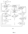
- step 402 starts in step 402
- step 404 it is checked if a full scan of the I-V curve has been performed within a predefined time window.
- the load may be varied from zero to infinity to track the PV panel IV curve from short circuit current to open circuit voltage in order to determine the maximum power point afresh. In an embodiment of the present invention, this is done by sweeping the duty cycle of the DC voltage -DC voltage converter 126 through its full range, i.e. from its minimum to maximum feasible duty cycle value.
- step 412 the operating voltage of the PV system 100 is measured and stored in the memory of the controller 124. If a recent full scan has been performed, the method may proceed to step 406 instead.
- the method may proceed to step 414, in which the operating point of the PV system 100 is fine-tuned using a modified P&O tracking algorithm, which will be explained in more detail later.
- the MPP tracking method enters a dormant state, in which it is assumed that the PV system operates at the MPP until a change in dP/dt, i.e. the differential power output of the system, exceeds a predefined threshold, as indicated in steps 406 and 416.
- the method executed by the controller 124 periodically determines an output power of the PV array 110 with the aid of the one or more sensors 122.
- the determination of dP/dt by the controller 124 also takes place during execution of modified tracking step 414. This is reflected by step 418, where it is checked if upon detection of dP/dt becoming non-negligible but not exceeding the predefined threshold, e.g. 0 ⁇ dP/dt ⁇ threshold, the modified tracking step 414 has successfully completed. If not, the method reverts back to step 414 to restart the modified tracking step 414 from the beginning.
- the P&O based tracking algorithm is prevented from oscillating around or diverging from the actual MPP of the PV system 100.
- step 420 upon completing the modified tracking step 414 and determining in step 418 that the modified tracking step 414 has resulted in the PV system 100 latching onto its actual MPP, it may be checked in step 420 if the difference between the actual MPP operating voltage and the MPP operating voltage stored in the memory of the controller exceeds a predefined threshold. This useful because as previously explained, the values of the MPP operating voltage exhibit relatively small variations under strongly varying illumination conditions for the PV array 110.
- the detection of a larger than expected difference between a previously determined MPP operating voltage and the operating voltage measured in step 420 is an indication of the PV system 100 operating under sub-optimal conditions, for instance because of system drift or because of the modified tracking step 414 latching onto a pseudo-peak of the actual I-V curve of the PV system 100.
- This may be rectified by performing a partial scan of the I-V characteristics of the PV system 100 in step 424 to bring the operating point of the PV system into the vicinity of its actual MPP, after which the modified tracking of the MPP, i.e. step 414, may be repeated to latch onto the actual MPP.
- a partial scan is typically performed in a predefined subrange of the full PV voltage range, for instance from 12V to 19V by changing the duty cycle over a smaller range. This is faster than a full scan and therefore leads to a lower PV power loss.
- the method may proceed to step 422 in which the measured voltage of the latched MPP is stored in the memory of the controller 124. This may be done by overwriting the previously stored MPP voltage or by adding the latched MPP voltage to the memory.
- the latter option has the advantage that the sign of the dP/dt measurement may be used to decide which MPP value is to be retrieved from the memory.
- the controller 124 may keep track of which is the most recent MPP voltage value stored in its memory and, upon a dP/dt measurement exceeding a predefined threshold indicative of an increase in illumination levels of the PV array 110, may check if a higher value MPP voltage is available in its memory and decide to restore this value instead of the most recently stored MPP voltage value, as the higher MPP voltage value can be expected to provide a more accurate estimate of the altered MPP voltage of the PV system 110.
- the controller 124 may check if a lower value MPP voltage is available in its memory and decide to restore this value instead of the most recently stored MPP voltage value, as the lower MPP voltage value can be expected to provide a more accurate estimate of the altered MPP voltage of the PV system 110.
- step 406 dP/dt has exceeded a predefined threshold, as this is indicative of the operating point of the PV system having moved away from its MPP. If the determined dP/dt does not exceed the predefined threshold, it may be assumed that the PV system 100 still operates at its MPP, such that the method may revert back to step 404 to check if the last performed full scan is still up to date, the outcome of this check leading to the method progressing to either step 412 or 406.
- step 406 if it is determined in step 406 that the absolute value of dP/dt exceeds the predefined threshold, it will be necessary to adjust the duty cycle of the DC voltage -DC voltage converter 126 to bring the operating point of the PV system 100 back to its MPP.
- this may be achieved by reactivating the MPP tracking algorithm in step 414, whereas for larger changes in the output power of the PV system 100, a two-step recalibration approach in which the operating voltage corresponding to the last known MPP of the PV system 100 is restored, after which the method may proceed to step 414 for fine-tuning the operating voltage of the PV system 100 using the tracking algorithm.
- step 408 it may be checked in step 408 if the difference between the actual operating voltage of the PV system 100 and the MPP voltage stored in the memory of the controller 120 exceeds a predefined threshold. If this difference is small enough, this is an indication that the current operating point of the PV system 100 still lies in the vicinity of its current MPP, such that the method 400 may immediately proceed to step 414. However, if this difference is relatively large, i.e. exceeds the predefined threshold, the operating point has shifted substantially, such that a faster convergence to the current MPP is achieved by first restoring the operating voltage of the last known MPP by appropriate adjustment of the duty cycle of the DC voltage -DC voltage converter 126 in step 410 before proceeding to step 414 or reverting to step 412. Reverting back to step 412 is preferred as this facilitates detection of further changes to the operation conditions of the PV system 100 which may have occurred during restoration of the MPP voltage in step 410.
- step 408 may be omitted from the method 400, in which case step 406 may be amended to compare the determined value of dP/dt against two thresholds T1 and T2, with T1 ⁇ T2.
- T1 is indicative of a change in operating conditions caused by e.g. temperature variations
- T2 is indicative of a change in operating conditions caused by e.g. illumination intensity variations.
- the proposed tracking algorithm is based on an alternating pattern of tracking runs in opposite directions on the I-V curve of the PV system 100.
- the duty cycle of the DC voltage -DC voltage converter 126 is systematically varied in one direction, e.g. systematically increased or systematically decreased, with the next tracking run being performed in the opposite direction.
- Each tracking run comprises a number of steps having a predefined step size, with the sensors 122 determining an output power of the PV array 110 after each step, with the controller 124 comparing the most recently measured output power (P act ) with the output power sampled after the previously performed step (P act-1 ).
- a tracking run is terminated when P act ⁇ P act-1 , after the next tracking run in the opposite direction is initiated.
- the step size of the next tracking run is reduced with respect to the step size of the last performed tracking run.
- the step size is the amount by which the duty cycle, e.g. the pulse width, of the DC voltage -DC voltage converter 126 is varied.
- the step size may be adjusted within a single tracking run based on the magnitude of the difference between P act and P act-1 , with the step size being reduced if this difference becomes smaller, such that an even faster convergence to MPP can be achieved.
- FIG. 5 An advantageous aspect of the above tracking algorithm is that the direction of the initial tracking run is independent of on which side of MPP the actual operating point of the PV system 100 lies. This is demonstrated in FIG. 5 , in which a three-run tracking algorithm implementing an alternating pattern of a systematic decrease (1), a systematic increase (2) and a systematic decrease (3) of the duty cycle of the DC voltage -DC voltage converter 126 results in the convergence to MPP from a starting operating voltage having a lower value than MPP as shown in the left pane of FIG. 5 , as well as from a starting operating voltage having a higher value than MPP as shown in the right pane of FIG. 5 .
Landscapes
- Engineering & Computer Science (AREA)
- Life Sciences & Earth Sciences (AREA)
- Sustainable Development (AREA)
- Sustainable Energy (AREA)
- Power Engineering (AREA)
- Physics & Mathematics (AREA)
- Electromagnetism (AREA)
- General Physics & Mathematics (AREA)
- Radar, Positioning & Navigation (AREA)
- Automation & Control Theory (AREA)
- Control Of Electrical Variables (AREA)
- Dc-Dc Converters (AREA)
Claims (13)
- Ein Verfahren (400) zum Tracking eines Maximum Power Points (MPP) eines Photovoltaiksystems (100), welches eine Schaltung (120) aufweist, die eine Steuerung (124) enthält, welche einen DC Spannung - DC Spannungs-Wandler (126) zum Wandeln eines Ausgangsstroms des Photovoltaiksystems steuert, wobei die Steuerung ferner einen Speicher aufweist, das Verfahren aufweisend:Messen (412) eines ersten Wertes einer Photovoltaiksystem Betriebsspannung bei einem initialen Maximum Power Point;Speichern des ersten Wertes in dem Speicher;Periodisches Abtasten (406) eines Leistungsausgangsniveaus des Photovoltaiksystems und auf ein Detektieren einer Änderung in dem Leistungsausgangsniveau hin, welches einen ersten Grenzwert überschreitet,Ermitteln (408) des aktuellen Wertes der Photovoltaiksystem Betriebsspannung und Vergleichen des aktuellen Wertes mit dem ersten Wert, undbedingt durch einen Unterschied zwischen dem aktuellen Wert und dem ersten Wert, welcher einen weiteren Grenzwert überschreitet:Lesen des ersten Wertes aus dem Speicher undEinstellen (410) eines Tastverhältnisses des DC Spannung - DC Spannungs-Wandlers bis die Photovoltaiksystem Betriebsspannung dem ersten Wert entspricht;wobei das Verfahren ferner aufweist
auf ein Detektieren einer Änderung in dem Leistungsausgangsniveau hin, welches den ersten Grenzwert überschreitet, Feineinstellen (414) des Tastverhältnisses des DC Spannung - DC Spannungs-Wandlers auf einen weiteren Maximum Power Point. - Das Verfahren gemäß Anspruch 1, wobei das Detektieren (406) einer Änderung in dem Leistungsniveau ein Detektieren der Änderung als eine Funktion der Verzögerung zwischen aufeinanderfolgenden Abtastungen aufweist.
- Das Verfahren (400) gemäß Anspruch 1 oder 2, wobei das Feineinstellen (414) aufweist:Tracking des Leistungsausgangs des Photovoltaiksystems nach dem Einstellschritt; undEinstellen des Leistungsausgangs des Photovoltaiksystems mittels abwechselndem Erhöhen und Verringern des Tastverhältnisses des DC Spannung - DC Spannungs-Wandlers bis ein weiterer Maximum Power Point des Photovoltaiksystems erreicht ist.
- Das Verfahren (400) gemäß Anspruch 3, ferner aufweisend:Messen (420) eines zweiten Wertes der Photovoltaiksystem Betriebsspannung bei dem weiteren Maximum Power Point; undSpeichern (422) des zweiten Wertes in dem Speicher mittels Überschreiben des ersten Wertes oder mittels Hinzufügen des zweiten Wertes in den Speicher.
- Das Verfahren (400) gemäß den Ansprüchen 3 oder 4, wobei:der Schritt des Erhöhens des Tastverhältnisses des DC Spannung - DC Spannungs-Wandlers aufweist
schrittweises Erhöhen des Tastverhältnisses des DC Spannung - DC Spannungs-Wandlers in einer Anzahl von Schritten, von denen jeder eine definierte Schrittweite hat, und
Messen des Leistungsausgangs des Photovoltaiksystems nach jedem Schritt bis der Leistungsausgang, der nach dem zweitletzten Schritt gemessen wurde, denLeistungsausgang überschreitet, der nach dem letzten Schritt gemessen wurde; wobei der Schritt des Verringerns des Tastverhältnisses des DC Spannung - DC Spannungs-Wandlers aufweist
schrittweises Verringern des Tastverhältnisses des DC Spannung - DC Spannungs-Wandlers in einer Anzahl von Schritten, von denen jeder eine definierte Schrittweite hat und
Messen des Leistungsausgangs des Photovoltaiksystems nach jedem Schritt bis der Leistungsausgang, der nach dem zweitletzten Schritt gemessen wurde, den Leistungsausgang überschreitet, der nach dem letzten Schritt gemessen wurde; undReduzieren der definierten Schrittweite nach der Beendigung des schrittweisen Erhöhens oder schrittweisen Verringerns des Tastverhältnisses. - Das Verfahren (400) gemäß irgendeinem der Ansprüche 3 bis 5, wobei die Gesamtanzahl des abwechselnden Erhöhens und Verringerns des Tastverhältnisses 3 ist.
- Das Verfahren (400) gemäß irgendeinem der Ansprüche 3 bis 6, wobei der Schritt (414) des Trackings des Leistungsausgangs des Photovoltaiksystems nach dem Einstellschritt aufweist
Ausführen einer Zweipunkt Leistungsausgangsmessung zum Ermitteln eines differentiellen Leistungsausgangs des Photovoltaiksystems; und
Initiieren des Einstellschritts, falls der differentielle Leistungsausgang unter einem zweiten Grenzwert liegt. - Das Verfahren (400) gemäß Anspruch 7, ferner aufweisend:Ausführen (416) der Zweipunkt Leistungsausgangsmessung zum Ermitteln eines differentiellen Leistungsausgangs des Photovoltaiksystems während der Feineinstellung; undNeustarten der Feineinstellung, wenn der ermittelte differentielle Leistungsausgang einen dritten Grenzwert überschreitet.
- Eine Photovoltaiksystem Steuerung (120), welche aufweist:einen DC Spannung - DC Spannungs-Wandler (126) zum Wandeln des Gleichstroms von einem Photovoltaiksystem in einen weiteren Strom; undeine Steuerung (124) zum Steuern des Tastverhältnisses des DC Spannung - DC Spannungs-Wandlers, wobei die Steuerung einen Speicher und einen Mikroprozessor aufweist, welcher Mikroprozessor einen Satz von Anweisungen zum Implementieren des Verfahrens gemäß irgendeinem der Ansprüche 1 bis 8 hat.
- Ein Photovoltaiksystem (100), welches die Photovoltaiksteuerung (120) gemäß Anspruch 9 aufweist, wobei das System ferner zumindest eine Photovoltaikzelle (112) aufweist, die einen Ausgang hat, der leitfähig mit einem Eingang des DC Spannung - DC Spannungs-Wandlers (126) gekoppelt ist.
- Das Photovoltaiksystem (100) gemäß Anspruch 10, welches ferner zumindest eine Batterie (130) aufweist, welche einen Eingang hat, der leitend an einen Ausgang des DC Spannung - DC Spannungs-Wandler (126) gekoppelt ist.
- Das Photovoltaiksystem (100) gemäß Anspruch 10 oder 11, welches ferner einen Sensor (122) zum Abtasten des Leistungsausgangs von der zumindest einen Photovoltaikzelle (112) aufweist, wobei die Steuerung (124) auf den Sensor (122) reagiert.
- Ein Computerprogramm Produkt, welches Programmcode zum Ausführen der Schritte des Verfahrens (400) gemäß irgendeinem der Ansprüche 1 bis 8 aufweist, wenn er auf einem Computerprozessor ausgeführt wird.
Priority Applications (3)
| Application Number | Priority Date | Filing Date | Title |
|---|---|---|---|
| EP20100164393 EP2390751B1 (de) | 2010-05-28 | 2010-05-28 | Verfahren zur Verfolgung des maximalen Leistungspunkts, Fotovoltaiksystemsteuerung und Fotovoltaiksystem |
| CN2011101406682A CN102354247A (zh) | 2010-05-28 | 2011-05-26 | 最大功率点跟踪方法、光致电压系统控制器、光致电压系统 |
| US13/117,380 US8963368B2 (en) | 2010-05-28 | 2011-05-27 | Maximum power point tracking method, photovoltaic system controller and photovoltaic system |
Applications Claiming Priority (1)
| Application Number | Priority Date | Filing Date | Title |
|---|---|---|---|
| EP20100164393 EP2390751B1 (de) | 2010-05-28 | 2010-05-28 | Verfahren zur Verfolgung des maximalen Leistungspunkts, Fotovoltaiksystemsteuerung und Fotovoltaiksystem |
Publications (2)
| Publication Number | Publication Date |
|---|---|
| EP2390751A1 EP2390751A1 (de) | 2011-11-30 |
| EP2390751B1 true EP2390751B1 (de) | 2013-09-04 |
Family
ID=42829912
Family Applications (1)
| Application Number | Title | Priority Date | Filing Date |
|---|---|---|---|
| EP20100164393 Not-in-force EP2390751B1 (de) | 2010-05-28 | 2010-05-28 | Verfahren zur Verfolgung des maximalen Leistungspunkts, Fotovoltaiksystemsteuerung und Fotovoltaiksystem |
Country Status (3)
| Country | Link |
|---|---|
| US (1) | US8963368B2 (de) |
| EP (1) | EP2390751B1 (de) |
| CN (1) | CN102354247A (de) |
Families Citing this family (36)
| Publication number | Priority date | Publication date | Assignee | Title |
|---|---|---|---|---|
| US8482156B2 (en) | 2009-09-09 | 2013-07-09 | Array Power, Inc. | Three phase power generation from a plurality of direct current sources |
| US8952672B2 (en) | 2011-01-17 | 2015-02-10 | Kent Kernahan | Idealized solar panel |
| US9136732B2 (en) * | 2011-10-15 | 2015-09-15 | James F Wolter | Distributed energy storage and power quality control in photovoltaic arrays |
| WO2013067429A1 (en) | 2011-11-03 | 2013-05-10 | Arraypower, Inc. | Direct current to alternating current conversion utilizing intermediate phase modulation |
| CN102768555A (zh) * | 2011-12-19 | 2012-11-07 | 国网电力科学研究院 | 一种适用于光伏系统的高效mppt控制策略 |
| TWI463290B (zh) * | 2012-03-22 | 2014-12-01 | 中原大學 | 具使用變頻及固定責任週期控制之功率增量輔助之增量電導最大功率點追蹤控制器之光電系統及其方法 |
| JP5894870B2 (ja) * | 2012-06-22 | 2016-03-30 | 日立アプライアンス株式会社 | 太陽光発電システム |
| CN102736661B (zh) * | 2012-07-03 | 2014-06-11 | 南京冠亚电源设备有限公司 | 一种光伏系统中的mppt控制方法 |
| EP2722724B1 (de) * | 2012-10-16 | 2017-10-11 | ABB Schweiz AG | Maximale Leistungspunktverfolgung |
| US20140103892A1 (en) * | 2012-10-16 | 2014-04-17 | Volterra Semiconductor Corporation | Scalable maximum power point tracking controllers and associated methods |
| US9939485B1 (en) * | 2012-11-14 | 2018-04-10 | National Technology & Engineering Solutions Of Sandia, Llc | Prognostics and health management of photovoltaic systems |
| JP6064642B2 (ja) * | 2013-02-08 | 2017-01-25 | オムロン株式会社 | 昇圧ユニット、パワーコンディショナ、太陽電池システム、プログラム、および電圧追従方法 |
| US9450405B2 (en) | 2013-02-25 | 2016-09-20 | Enphase Energy, Inc. | Method and apparatus for reactive power capable inverters |
| CN103777672B (zh) * | 2014-01-08 | 2015-10-28 | 西安龙腾新能源科技发展有限公司 | 光伏电池板曲线剧变后的输出功率恢复方法 |
| US10193378B2 (en) | 2014-08-15 | 2019-01-29 | Hilos Ventures, Llc | Apparatus and methods for control of power flow and battery charge |
| CN104238622B (zh) * | 2014-08-18 | 2016-04-20 | 南京航空航天大学 | 基于局部阴影下光伏阵列电流特性的输出功率获取方法 |
| CN104199507B (zh) * | 2014-08-22 | 2017-08-29 | 上海寰晟新能源科技有限公司 | 基于p‑u曲率特性的光伏最大功率跟踪系统及方法 |
| CN104238624B (zh) * | 2014-10-09 | 2016-03-30 | 阳光电源股份有限公司 | 一种最大功率点的跟踪方法及装置 |
| CN104238625B (zh) * | 2014-10-15 | 2016-02-10 | 珠海格力电器股份有限公司 | 最大功率跟踪控制方法及装置 |
| CN105138066A (zh) * | 2015-09-29 | 2015-12-09 | 上海电机学院 | 光伏阵列的最大功率跟踪控制系统以及方法 |
| CN106371495B (zh) * | 2016-10-14 | 2017-08-25 | 西安电子科技大学 | 用于微能量获取的mppt控制电路及能量获取电路 |
| CN106406417B (zh) * | 2016-11-22 | 2017-12-26 | 瑞德兴阳新能源技术有限公司 | 时控型太阳能跟踪支架控制器的最大功率跟踪控制方法 |
| KR20230129243A (ko) | 2020-12-23 | 2023-09-07 | 페데랄노에 고수다르스타브노에 부유젯노에 오브라조바텔노에 우크레시데니에 빗셔고 오브라조바니야 ≪모스코브스키이 고수다르스타브니이 유니베르시티에 이메니 엠.브이.로모노소바≫ (엠지유) | 유기-무기 복합체 할로게나이드 필름의 제조 |
| CN112925377B (zh) * | 2021-02-01 | 2022-07-29 | 浙江晶科能源有限公司 | 光伏系统及光伏系统的最大功率跟踪方法 |
| JP7414045B2 (ja) * | 2021-08-10 | 2024-01-16 | 株式会社村田製作所 | 電力制御装置 |
| CN114035644B (zh) * | 2021-10-21 | 2023-07-11 | 西安理工大学 | 一种改进p&o法消除光伏发电系统稳态振荡的控制方法 |
| CN114006404B (zh) * | 2021-11-12 | 2024-04-26 | 广东电网有限责任公司 | 一种光伏电力电子变压器的运行控制方法及装置 |
| CN114154453B (zh) * | 2021-11-26 | 2025-07-22 | 南京航空航天大学 | 一种基于gmppt技术的微波整流端能量管理方法 |
| CN114200999B (zh) * | 2021-12-09 | 2023-03-10 | 国网山东省电力公司电力科学研究院 | 一种自适应变步长最大功率点跟踪控制方法、系统及应用 |
| CN114442724B (zh) * | 2021-12-30 | 2023-03-17 | 南京航空航天大学 | 基于光伏电池短路电流估计和扰动观察的最大功率点跟踪方法 |
| CN115268559B (zh) * | 2022-05-23 | 2023-07-14 | 北京华能新锐控制技术有限公司 | 用于永磁同步风力发电机的最大功率点跟踪鲁棒控制方法 |
| CN115813340A (zh) * | 2022-11-19 | 2023-03-21 | 上海电机学院 | P-v曲线快速变化情况下的mppt算法 |
| CN115951753A (zh) * | 2022-12-23 | 2023-04-11 | 惠州汇能精电科技有限公司 | 一种光伏组件mppt方法、装置、设备及介质 |
| CN116755504B (zh) * | 2023-06-29 | 2025-08-05 | 常熟市通用电器厂有限公司 | 一种大功率组串式光伏逆变器的最大功率点跟踪控制方法 |
| CN118381121B (zh) * | 2024-04-19 | 2025-09-23 | 中南大学 | 一种基于电感电流的分布式光伏电池储能系统功率优化控制方法 |
| CN119270991B (zh) * | 2024-11-01 | 2025-12-09 | 哈尔滨工业大学 | 一种基于时滞极值搜索的光伏系统最大功率点跟踪控制方法 |
Family Cites Families (6)
| Publication number | Priority date | Publication date | Assignee | Title |
|---|---|---|---|---|
| JP3554116B2 (ja) * | 1996-09-06 | 2004-08-18 | キヤノン株式会社 | 電力制御装置及びそれを用いた太陽光発電システム |
| JP4999280B2 (ja) * | 2005-03-11 | 2012-08-15 | 財団法人神奈川科学技術アカデミー | 電力制御方法および電力制御装置 |
| DE102005032864B4 (de) * | 2005-07-14 | 2011-04-14 | Sma Solar Technology Ag | Verfahren zum Auffinden eines Leistungsmaximums eines Photovoltaik-Generators |
| CN100508327C (zh) * | 2007-06-08 | 2009-07-01 | 清华大学 | 一种快速稳定实现最大功率跟踪的光伏三相并网控制方法 |
| US8390147B2 (en) * | 2009-05-13 | 2013-03-05 | Solar Semiconductor, Inc. | Methods and apparatuses for photovoltaic power management |
| CN101651436B (zh) * | 2009-09-16 | 2013-04-03 | 阳光电源股份有限公司 | 一种高精度最大功率点跟踪方法 |
-
2010
- 2010-05-28 EP EP20100164393 patent/EP2390751B1/de not_active Not-in-force
-
2011
- 2011-05-26 CN CN2011101406682A patent/CN102354247A/zh active Pending
- 2011-05-27 US US13/117,380 patent/US8963368B2/en not_active Expired - Fee Related
Also Published As
| Publication number | Publication date |
|---|---|
| US20110291480A1 (en) | 2011-12-01 |
| EP2390751A1 (de) | 2011-11-30 |
| CN102354247A (zh) | 2012-02-15 |
| US8963368B2 (en) | 2015-02-24 |
Similar Documents
| Publication | Publication Date | Title |
|---|---|---|
| EP2390751B1 (de) | Verfahren zur Verfolgung des maximalen Leistungspunkts, Fotovoltaiksystemsteuerung und Fotovoltaiksystem | |
| US7420354B2 (en) | Method and apparatus for controlling power drawn from an energy converter | |
| US9354652B2 (en) | Maximum power point tracking method and device, and photovoltaic power generation system | |
| Sera et al. | Optimized maximum power point tracker for fast changing environmental conditions | |
| Koutroulis et al. | A new technique for tracking the global maximum power point of PV arrays operating under partial-shading conditions | |
| KR101452776B1 (ko) | 태양광 시스템 | |
| US8816667B2 (en) | Maximum power point tracking method | |
| Rawat et al. | Hill climbing techniques for tracking maximum power point in solar photovoltaic systems-a review | |
| JP6173099B2 (ja) | 太陽光電源の最大電力点を検出するための電力曲線測定の発生を制御する装置及び方法 | |
| KR101598464B1 (ko) | 하이브리드 mppt제어에 의한 태양광발전시스템의 효율개선 방법 | |
| CN107742902B (zh) | 一种光伏逆变器的多路mppt输入模式判断方法 | |
| CN107168447B (zh) | 一种基于改进电导增量法的光伏逆变器多峰值mppt方法 | |
| EP4293896B1 (de) | Verfahren und vorrichtung zur verfolgung eines maximalen leistungspunktes | |
| WO2016074649A1 (zh) | 最大电力点追踪装置及太阳能电池模块的评估方法 | |
| Zhu et al. | Research and test of power-loop-based dynamic multi-peak MPPT algorithm | |
| Yang et al. | A modified P&O MPPT algorithm for single-phase PV systems based on deadbeat control | |
| WO2012020103A2 (en) | Method for operation of a photovoltaic generator at an operating point of maximum power | |
| KR20210133655A (ko) | 태양광 발전 시스템 및 최대 전력점 추적 제어 방법 | |
| JP5988208B2 (ja) | パワーコンディショナ | |
| CN119543679A (zh) | 基于特征识别模型的逆变器控制方法 | |
| JP5903341B2 (ja) | 発電制御装置、太陽光発電システム、および発電制御方法 | |
| KR101598458B1 (ko) | 태양광 발전효율 개선을 위한 태양광 인버터 시스템 및 그 제어 방법 | |
| JP6551143B2 (ja) | パワーコンディショナ及び太陽光発電システム | |
| Durusu et al. | Performance comparison of widely-used maximum power point tracker algorithms under real environmental conditions | |
| Liu et al. | A MPPT algorithm based on PSO for PV array under partially shaded condition |
Legal Events
| Date | Code | Title | Description |
|---|---|---|---|
| AK | Designated contracting states |
Kind code of ref document: A1 Designated state(s): AL AT BE BG CH CY CZ DE DK EE ES FI FR GB GR HR HU IE IS IT LI LT LU LV MC MK MT NL NO PL PT RO SE SI SK SM TR |
|
| AX | Request for extension of the european patent |
Extension state: BA ME RS |
|
| PUAI | Public reference made under article 153(3) epc to a published international application that has entered the european phase |
Free format text: ORIGINAL CODE: 0009012 |
|
| 17P | Request for examination filed |
Effective date: 20120530 |
|
| GRAP | Despatch of communication of intention to grant a patent |
Free format text: ORIGINAL CODE: EPIDOSNIGR1 |
|
| INTG | Intention to grant announced |
Effective date: 20130513 |
|
| GRAS | Grant fee paid |
Free format text: ORIGINAL CODE: EPIDOSNIGR3 |
|
| GRAA | (expected) grant |
Free format text: ORIGINAL CODE: 0009210 |
|
| AK | Designated contracting states |
Kind code of ref document: B1 Designated state(s): AL AT BE BG CH CY CZ DE DK EE ES FI FR GB GR HR HU IE IS IT LI LT LU LV MC MK MT NL NO PL PT RO SE SI SK SM TR |
|
| REG | Reference to a national code |
Ref country code: GB Ref legal event code: FG4D |
|
| REG | Reference to a national code |
Ref country code: CH Ref legal event code: EP |
|
| REG | Reference to a national code |
Ref country code: AT Ref legal event code: REF Ref document number: 630822 Country of ref document: AT Kind code of ref document: T Effective date: 20130915 |
|
| REG | Reference to a national code |
Ref country code: IE Ref legal event code: FG4D |
|
| REG | Reference to a national code |
Ref country code: DE Ref legal event code: R096 Ref document number: 602010009960 Country of ref document: DE Effective date: 20131031 |
|
| REG | Reference to a national code |
Ref country code: AT Ref legal event code: MK05 Ref document number: 630822 Country of ref document: AT Kind code of ref document: T Effective date: 20130904 |
|
| REG | Reference to a national code |
Ref country code: NL Ref legal event code: VDEP Effective date: 20130904 |
|
| PG25 | Lapsed in a contracting state [announced via postgrant information from national office to epo] |
Ref country code: HR Free format text: LAPSE BECAUSE OF FAILURE TO SUBMIT A TRANSLATION OF THE DESCRIPTION OR TO PAY THE FEE WITHIN THE PRESCRIBED TIME-LIMIT Effective date: 20130904 Ref country code: NO Free format text: LAPSE BECAUSE OF FAILURE TO SUBMIT A TRANSLATION OF THE DESCRIPTION OR TO PAY THE FEE WITHIN THE PRESCRIBED TIME-LIMIT Effective date: 20131204 Ref country code: SE Free format text: LAPSE BECAUSE OF FAILURE TO SUBMIT A TRANSLATION OF THE DESCRIPTION OR TO PAY THE FEE WITHIN THE PRESCRIBED TIME-LIMIT Effective date: 20130904 Ref country code: CY Free format text: LAPSE BECAUSE OF FAILURE TO SUBMIT A TRANSLATION OF THE DESCRIPTION OR TO PAY THE FEE WITHIN THE PRESCRIBED TIME-LIMIT Effective date: 20130731 Ref country code: AT Free format text: LAPSE BECAUSE OF FAILURE TO SUBMIT A TRANSLATION OF THE DESCRIPTION OR TO PAY THE FEE WITHIN THE PRESCRIBED TIME-LIMIT Effective date: 20130904 Ref country code: LT Free format text: LAPSE BECAUSE OF FAILURE TO SUBMIT A TRANSLATION OF THE DESCRIPTION OR TO PAY THE FEE WITHIN THE PRESCRIBED TIME-LIMIT Effective date: 20130904 |
|
| REG | Reference to a national code |
Ref country code: NL Ref legal event code: VDEP Effective date: 20130904 |
|
| REG | Reference to a national code |
Ref country code: LT Ref legal event code: MG4D |
|
| PG25 | Lapsed in a contracting state [announced via postgrant information from national office to epo] |
Ref country code: GR Free format text: LAPSE BECAUSE OF FAILURE TO SUBMIT A TRANSLATION OF THE DESCRIPTION OR TO PAY THE FEE WITHIN THE PRESCRIBED TIME-LIMIT Effective date: 20131205 Ref country code: PL Free format text: LAPSE BECAUSE OF FAILURE TO SUBMIT A TRANSLATION OF THE DESCRIPTION OR TO PAY THE FEE WITHIN THE PRESCRIBED TIME-LIMIT Effective date: 20130904 Ref country code: LV Free format text: LAPSE BECAUSE OF FAILURE TO SUBMIT A TRANSLATION OF THE DESCRIPTION OR TO PAY THE FEE WITHIN THE PRESCRIBED TIME-LIMIT Effective date: 20130904 Ref country code: SI Free format text: LAPSE BECAUSE OF FAILURE TO SUBMIT A TRANSLATION OF THE DESCRIPTION OR TO PAY THE FEE WITHIN THE PRESCRIBED TIME-LIMIT Effective date: 20130904 Ref country code: FI Free format text: LAPSE BECAUSE OF FAILURE TO SUBMIT A TRANSLATION OF THE DESCRIPTION OR TO PAY THE FEE WITHIN THE PRESCRIBED TIME-LIMIT Effective date: 20130904 |
|
| PG25 | Lapsed in a contracting state [announced via postgrant information from national office to epo] |
Ref country code: BE Free format text: LAPSE BECAUSE OF FAILURE TO SUBMIT A TRANSLATION OF THE DESCRIPTION OR TO PAY THE FEE WITHIN THE PRESCRIBED TIME-LIMIT Effective date: 20130904 Ref country code: CY Free format text: LAPSE BECAUSE OF FAILURE TO SUBMIT A TRANSLATION OF THE DESCRIPTION OR TO PAY THE FEE WITHIN THE PRESCRIBED TIME-LIMIT Effective date: 20130904 |
|
| PG25 | Lapsed in a contracting state [announced via postgrant information from national office to epo] |
Ref country code: SK Free format text: LAPSE BECAUSE OF FAILURE TO SUBMIT A TRANSLATION OF THE DESCRIPTION OR TO PAY THE FEE WITHIN THE PRESCRIBED TIME-LIMIT Effective date: 20130904 Ref country code: IS Free format text: LAPSE BECAUSE OF FAILURE TO SUBMIT A TRANSLATION OF THE DESCRIPTION OR TO PAY THE FEE WITHIN THE PRESCRIBED TIME-LIMIT Effective date: 20140104 Ref country code: NL Free format text: LAPSE BECAUSE OF FAILURE TO SUBMIT A TRANSLATION OF THE DESCRIPTION OR TO PAY THE FEE WITHIN THE PRESCRIBED TIME-LIMIT Effective date: 20130904 Ref country code: EE Free format text: LAPSE BECAUSE OF FAILURE TO SUBMIT A TRANSLATION OF THE DESCRIPTION OR TO PAY THE FEE WITHIN THE PRESCRIBED TIME-LIMIT Effective date: 20130904 Ref country code: RO Free format text: LAPSE BECAUSE OF FAILURE TO SUBMIT A TRANSLATION OF THE DESCRIPTION OR TO PAY THE FEE WITHIN THE PRESCRIBED TIME-LIMIT Effective date: 20130904 Ref country code: CZ Free format text: LAPSE BECAUSE OF FAILURE TO SUBMIT A TRANSLATION OF THE DESCRIPTION OR TO PAY THE FEE WITHIN THE PRESCRIBED TIME-LIMIT Effective date: 20130904 |
|
| PG25 | Lapsed in a contracting state [announced via postgrant information from national office to epo] |
Ref country code: ES Free format text: LAPSE BECAUSE OF FAILURE TO SUBMIT A TRANSLATION OF THE DESCRIPTION OR TO PAY THE FEE WITHIN THE PRESCRIBED TIME-LIMIT Effective date: 20130904 |
|
| REG | Reference to a national code |
Ref country code: DE Ref legal event code: R097 Ref document number: 602010009960 Country of ref document: DE |
|
| PG25 | Lapsed in a contracting state [announced via postgrant information from national office to epo] |
Ref country code: PT Free format text: LAPSE BECAUSE OF FAILURE TO SUBMIT A TRANSLATION OF THE DESCRIPTION OR TO PAY THE FEE WITHIN THE PRESCRIBED TIME-LIMIT Effective date: 20140106 |
|
| PLBE | No opposition filed within time limit |
Free format text: ORIGINAL CODE: 0009261 |
|
| STAA | Information on the status of an ep patent application or granted ep patent |
Free format text: STATUS: NO OPPOSITION FILED WITHIN TIME LIMIT |
|
| 26N | No opposition filed |
Effective date: 20140605 |
|
| PG25 | Lapsed in a contracting state [announced via postgrant information from national office to epo] |
Ref country code: IT Free format text: LAPSE BECAUSE OF FAILURE TO SUBMIT A TRANSLATION OF THE DESCRIPTION OR TO PAY THE FEE WITHIN THE PRESCRIBED TIME-LIMIT Effective date: 20130904 |
|
| REG | Reference to a national code |
Ref country code: DE Ref legal event code: R097 Ref document number: 602010009960 Country of ref document: DE Effective date: 20140605 |
|
| PG25 | Lapsed in a contracting state [announced via postgrant information from national office to epo] |
Ref country code: DK Free format text: LAPSE BECAUSE OF FAILURE TO SUBMIT A TRANSLATION OF THE DESCRIPTION OR TO PAY THE FEE WITHIN THE PRESCRIBED TIME-LIMIT Effective date: 20130904 |
|
| PG25 | Lapsed in a contracting state [announced via postgrant information from national office to epo] |
Ref country code: LU Free format text: LAPSE BECAUSE OF FAILURE TO SUBMIT A TRANSLATION OF THE DESCRIPTION OR TO PAY THE FEE WITHIN THE PRESCRIBED TIME-LIMIT Effective date: 20140528 |
|
| REG | Reference to a national code |
Ref country code: CH Ref legal event code: PL |
|
| GBPC | Gb: european patent ceased through non-payment of renewal fee |
Effective date: 20140528 |
|
| PG25 | Lapsed in a contracting state [announced via postgrant information from national office to epo] |
Ref country code: CH Free format text: LAPSE BECAUSE OF NON-PAYMENT OF DUE FEES Effective date: 20140531 Ref country code: MC Free format text: LAPSE BECAUSE OF FAILURE TO SUBMIT A TRANSLATION OF THE DESCRIPTION OR TO PAY THE FEE WITHIN THE PRESCRIBED TIME-LIMIT Effective date: 20130904 Ref country code: LI Free format text: LAPSE BECAUSE OF NON-PAYMENT OF DUE FEES Effective date: 20140531 |
|
| REG | Reference to a national code |
Ref country code: IE Ref legal event code: MM4A |
|
| REG | Reference to a national code |
Ref country code: FR Ref legal event code: ST Effective date: 20150130 |
|
| PG25 | Lapsed in a contracting state [announced via postgrant information from national office to epo] |
Ref country code: IE Free format text: LAPSE BECAUSE OF NON-PAYMENT OF DUE FEES Effective date: 20140528 |
|
| PG25 | Lapsed in a contracting state [announced via postgrant information from national office to epo] |
Ref country code: GB Free format text: LAPSE BECAUSE OF NON-PAYMENT OF DUE FEES Effective date: 20140528 Ref country code: FR Free format text: LAPSE BECAUSE OF NON-PAYMENT OF DUE FEES Effective date: 20140602 |
|
| REG | Reference to a national code |
Ref country code: DE Ref legal event code: R081 Ref document number: 602010009960 Country of ref document: DE Owner name: LLL HOLDINGS 6, LLC, WILMINGTON, US Free format text: FORMER OWNER: NXP B.V., EINDHOVEN, NL Ref country code: DE Ref legal event code: R081 Ref document number: 602010009960 Country of ref document: DE Owner name: III HOLDINGS 6, LLC, WILMINGTON, US Free format text: FORMER OWNER: NXP B.V., EINDHOVEN, NL |
|
| PG25 | Lapsed in a contracting state [announced via postgrant information from national office to epo] |
Ref country code: MT Free format text: LAPSE BECAUSE OF FAILURE TO SUBMIT A TRANSLATION OF THE DESCRIPTION OR TO PAY THE FEE WITHIN THE PRESCRIBED TIME-LIMIT Effective date: 20130904 |
|
| PG25 | Lapsed in a contracting state [announced via postgrant information from national office to epo] |
Ref country code: SM Free format text: LAPSE BECAUSE OF FAILURE TO SUBMIT A TRANSLATION OF THE DESCRIPTION OR TO PAY THE FEE WITHIN THE PRESCRIBED TIME-LIMIT Effective date: 20130904 |
|
| PG25 | Lapsed in a contracting state [announced via postgrant information from national office to epo] |
Ref country code: BG Free format text: LAPSE BECAUSE OF FAILURE TO SUBMIT A TRANSLATION OF THE DESCRIPTION OR TO PAY THE FEE WITHIN THE PRESCRIBED TIME-LIMIT Effective date: 20130904 |
|
| PG25 | Lapsed in a contracting state [announced via postgrant information from national office to epo] |
Ref country code: TR Free format text: LAPSE BECAUSE OF FAILURE TO SUBMIT A TRANSLATION OF THE DESCRIPTION OR TO PAY THE FEE WITHIN THE PRESCRIBED TIME-LIMIT Effective date: 20130904 Ref country code: HU Free format text: LAPSE BECAUSE OF FAILURE TO SUBMIT A TRANSLATION OF THE DESCRIPTION OR TO PAY THE FEE WITHIN THE PRESCRIBED TIME-LIMIT; INVALID AB INITIO Effective date: 20100528 |
|
| REG | Reference to a national code |
Ref country code: DE Ref legal event code: R082 Ref document number: 602010009960 Country of ref document: DE Representative=s name: MUELLER-BORE & PARTNER PATENTANWAELTE PARTG MB, DE Ref country code: DE Ref legal event code: R081 Ref document number: 602010009960 Country of ref document: DE Owner name: III HOLDINGS 6, LLC, WILMINGTON, US Free format text: FORMER OWNER: LLL HOLDINGS 6, LLC, WILMINGTON, DEL., US |
|
| PG25 | Lapsed in a contracting state [announced via postgrant information from national office to epo] |
Ref country code: MK Free format text: LAPSE BECAUSE OF FAILURE TO SUBMIT A TRANSLATION OF THE DESCRIPTION OR TO PAY THE FEE WITHIN THE PRESCRIBED TIME-LIMIT Effective date: 20130904 |
|
| PG25 | Lapsed in a contracting state [announced via postgrant information from national office to epo] |
Ref country code: AL Free format text: LAPSE BECAUSE OF FAILURE TO SUBMIT A TRANSLATION OF THE DESCRIPTION OR TO PAY THE FEE WITHIN THE PRESCRIBED TIME-LIMIT Effective date: 20130904 |
|
| PGFP | Annual fee paid to national office [announced via postgrant information from national office to epo] |
Ref country code: DE Payment date: 20220527 Year of fee payment: 13 |
|
| REG | Reference to a national code |
Ref country code: DE Ref legal event code: R119 Ref document number: 602010009960 Country of ref document: DE |
|
| PG25 | Lapsed in a contracting state [announced via postgrant information from national office to epo] |
Ref country code: DE Free format text: LAPSE BECAUSE OF NON-PAYMENT OF DUE FEES Effective date: 20231201 |