EP2390974B1 - Elektrische Schalttafel mit verbesserter Bogenschutzanordnung - Google Patents
Elektrische Schalttafel mit verbesserter Bogenschutzanordnung Download PDFInfo
- Publication number
- EP2390974B1 EP2390974B1 EP10163878.1A EP10163878A EP2390974B1 EP 2390974 B1 EP2390974 B1 EP 2390974B1 EP 10163878 A EP10163878 A EP 10163878A EP 2390974 B1 EP2390974 B1 EP 2390974B1
- Authority
- EP
- European Patent Office
- Prior art keywords
- openings
- opening
- venting area
- barrier element
- switchgear panel
- Prior art date
- Legal status (The legal status is an assumption and is not a legal conclusion. Google has not performed a legal analysis and makes no representation as to the accuracy of the status listed.)
- Active
Links
Images




Classifications
-
- H—ELECTRICITY
- H02—GENERATION; CONVERSION OR DISTRIBUTION OF ELECTRIC POWER
- H02B—BOARDS, SUBSTATIONS OR SWITCHING ARRANGEMENTS FOR THE SUPPLY OR DISTRIBUTION OF ELECTRIC POWER
- H02B13/00—Arrangement of switchgear in which switches are enclosed in, or structurally associated with, a casing, e.g. cubicle
- H02B13/02—Arrangement of switchgear in which switches are enclosed in, or structurally associated with, a casing, e.g. cubicle with metal casing
- H02B13/025—Safety arrangements, e.g. in case of excessive pressure or fire due to electrical defect
-
- H—ELECTRICITY
- H02—GENERATION; CONVERSION OR DISTRIBUTION OF ELECTRIC POWER
- H02B—BOARDS, SUBSTATIONS OR SWITCHING ARRANGEMENTS FOR THE SUPPLY OR DISTRIBUTION OF ELECTRIC POWER
- H02B1/00—Frameworks, boards, panels, desks, casings; Details of substations or switching arrangements
- H02B1/015—Boards, panels, desks; Parts thereof or accessories therefor
- H02B1/04—Mounting thereon of switches or of other devices in general, the switch or device having, or being without, casing
- H02B1/056—Mounting on plugboards
- H02B1/0565—Mounting on plugboards by means of an adapter carrying one or more apparatuses
Definitions
- the present invention relates to an electric switchgear panel with an improved arc protection assembly.
- switchgear panels are electrical components used as node points, while cables and overhead lines represent the conjunction of the various nodes.
- switchgear panels which can be also indicated with the equivalent terms of electric switchboards, or simply switchgear or electric panels, or similar definitions, usually comprise a metallic enclosure that is internally divided into several compartments or cells housing various apparatuses and equipment.
- a switching unit such as a circuit breaker
- main cables such as bus-bars, feeding power from an electrical source
- a further compartment houses a system of cables suitable to be connected to a load, for example an electrical motor.
- switchgear panels may comprise other components, such as current transformers, fuses, voltage transformers, et cetera.
- Arcing events e.g. arcing faults or flashes, occur when electric current arcs strike for instance between two conductors inside the switchgear cabinet, e.g. between phase conductors, phase and neutral conductors, between the contacts of the circuit breaker used, or between a conductor and ground, et cetera.
- arcing faults occur, in particular in medium- to high-voltage power applications wherein levels of energy involved are quite significant, the ionized gas associated with them may be released at significant pressures and temperatures sufficient to severely damage or destroy the switchgear panel itself, and/or the devices and equipment housed inside, and be also potentially dangerous for operating personnel or equipment outside the enclosure.
- the materials involved in or exposed to the arc produce hot decomposition products, both gaseous and particulate either plastic and/or metallic, which may be discharged to the outside of the enclosure together with or in addition to hot gases and flames.
- a first solution foresees the evaluation of current perturbations in a conductor which are indicative of an arcing event; however, this solution may require onerous processing demands resulting in an undesirably long reaction time for identifying an arcing event.
- Another solution uses pressure sensors to monitor the increase in pressure indicative of an arcing event; also this solution may require significant time before pressure increases to detectable levels, resulting in long reaction times before mitigating an arcing event.
- optical detectors such as optical fibres
- this solution may result in erroneous detections as the light sensors may detect light from sources independent from electric arcs. This would result in unwarranted tripping of protection units which would put out of service the whole switchgear panel or parts thereof.
- arc-resistant switchgear cabinets able to mechanically withstand the pressure waves and temperatures of the hot gases associated with an arcing fault; in some other cases there are provided specific parts of the enclosure which may blow up due to an electric are occurring inside the enclosure.
- suitable paths for channelling and venting the hot gases and flames generated by an arcing fault out from the internal compartments towards a desired area For example, there are provided flaps or ducts which lead the hot gases, flames and particulate to the outside environment through the ceiling of the enclosure or in some cases even underground, i.e. towards zones far away from possible presence of operating personnel.
- a switchgear panel which comprises an enclosure having a plurality of walls which delimit an internal volume suitable to accommodate corresponding electrical or electronic equipment, at least a first wall of said plurality of walls being provided with one or more openings suitable to allow venting outside the enclosure hot gases, flames, particulates, which may be generated when an arc strikes inside the panel.
- the switchgear panel according to the invention comprises in particular an arc protection assembly which is positioned outside the enclosure and is operatively associated to at least said first wall and comprises at least a first barrier element having a first surface which is provided with one or more first through openings defining each a first venting area through which said hot gases, flames, particulates, coming from the inside of the enclosure can pass through, and a second barrier element which is operatively associated to said first barrier element and comprises a second surface provided with one or more second through openings defining each a second venting area through which can pass the hot gases, flames, particulates, coming from the inside of the enclosure and having already passed said one or more openings and the first openings.
- the first venting area of each first through opening of said one or more first through openings is different from the second venting area of each second through opening of said one or more second through openings.
- figure 1 is a perspective view showing an electric switchgear panel provided with an arc protection assembly according to the invention
- Figure 1 shows an example of an electric switchgear panel according to the invention, indicated by the overall numeral reference 100 which comprises, according to known solutions, an enclosure having a plurality of walls, namely a rear wall 1, a front wall 2, two lateral walls 3, 6, a top wall 4 and a bottom wall 5, which all together define an internal volume suitable to accommodate various electrical or electronic equipment and/or devices, such as for example, a circuit breaker, bus-bars, cables, electronic relays et cetera.
- a circuit breaker, bus-bars, cables, electronic relays et cetera such as for example, a circuit breaker, bus-bars, cables, electronic relays et cetera.
- At least one of the walls of the enclosure in the embodiment illustrated preferably the rear wall 1 (hereinafter referred to as the "first wall"), is provided with one or more openings 7, e.g. two as illustrated schematically in figure 1 with dotted lines; such one or more opening(s) 7 are suitable to allow venting outside the enclosure the hot gases, flames, particulate, and the like, which may be generated when an electric arc strikes inside the panel 100.
- the switchgear panel 100 according to the present invention comprises an arc protection assembly which is globally indicated by the reference number 10 and is operatively associated to the enclosure of the panel 100.
- the arc protection assembly 10 is positioned outside the enclosure and is operatively associated to at least the first wall 1 and - as it will result more clearly from the following description- it is devised to mitigate the effects resulting from any electric arc striking inside the enclosure, e.g. hot gases, flames, particulates.
- the arc protection assembly 10 preferably comprises at least a first barrier element 11 and a second barrier element 21, some exemplary embodiments of which are illustrated in figures 2 and 3 , respectively.
- the first barrier element 11 comprises a first surface 15 which is provided with one or more first through openings 12.
- each first opening 12 delimit a through area 13, i.e. a venting area 13 through which the hot gases, flames, particulates, coming from the inside of the enclosure can pass through; the various venting areas 13 defined by each of the first openings 12 are equal to each other.
- the one or more first through openings 12 which delimit all a respective equal venting area 13 are randomly positioned on the first surface 15.
- the first barrier element 11 is constituted by a metallic plate which, seen in section from a top or bottom plan view, is U-shaped.
- the central side of the U-shaped plate constitutes the first surface 15 and is suitably perforated so as to have the one or more, preferably a plurality of, first though openings 12.
- the first through openings 12 are constituted by circular through holes 12, with the front area of each circle forming the respective venting area 13 (an exemplary one of which is marked with points in the magnified portion (A)).
- first through openings of whatever shape provided it is compatible for the scope of the present invention, e.g. there can be squared through openings, or elliptic through openings, et cetera, delimiting each the same respective venting area 13; in addition, one or more first through openings 12 can be also provided on the two lateral sides 16, 17 of the U-shaped plate 11.
- the barrier element 11 can be provided with other openings whose perimetrical rims may delimit a different through area; for example, some openings 18, 19 may be used just for receiving fixing screws, as well as to contribute to venting.
- the number of first through openings 12 defining each a respective same venting area 13 provided on the first surface 15 is preferably predominant, i.e. at least more than half the holes provided on the first surface 15 is constituted by the indicated first through openings 12.
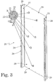
- the second barrier element 21 is operatively associated to the first barrier element 11 and comprises, as illustrated in figure 3 , a second surface 25 which is provided with one or more second through openings 22.
- a portion (B) of the second surface 25 has been magnified; it has to be understood that the magnified portion (B) extends over at least a predominant (i.e. more than 50%) part of, if not almost all, the entire second surface 25.
- each second opening 22 delimit a through area 23, i.e. a venting area 23 through which can pass the hot gases, flames, particulates, coming from the inside of the enclosure and having already passed the opening(s) 7 and the first openings 12; the various venting areas 23 defined by each of the second openings 22 are equal to each other.
- the one or more second through openings 22 which delimit all a respective equal venting area 23 are randomly positioned on the second surface 25.
- the second barrier element 21 is constituted by a metallic plate which, seen in section from a top or bottom plan view, is substantially U-shaped.
- the central side of the U-shaped plate 21 constitutes the second surface 25 and is suitably perforated so as to have the one or more, preferably a plurality of, second though openings 22.
- the second through openings 22 are constituted by circular through holes 22, with the front area of each circle forming the respective venting area 23 (an exemplary one of which is marked with points in the magnified portion (B)).
- second barrier element 21 through openings of whatever shape as also indicated above for the first barrier element 21, e.g. squared, elliptic, et cetera, delimiting each a respective same area 23; in addition, one or more second through openings 22 can be also provided on the two lateral sides 26, 27 of the U-shaped plate 21.
- the two sides 26, 27 present an outwardly folded rim 28 suitable to allow fixing to corresponding walls of the enclosure, as it will be described hereinafter.
- the second barrier element 21 may be provided with openings 29 additional to the one or more second through openings 22 defining all the same respective venting areas 23, and whose perimetrical rims may delimit a different through area; for example, some openings 29, may be used just for receiving fixing screws, as well as to contribute to venting.
- the number of second through openings 22 defining each a respective same venting area 23 provided on the second surface 25 is preferably predominant, i.e. at least more than half the holes provided on the second surface 25 is constituted by the indicated second through openings 22.
- the first venting area 13 delimited by the rims of each first through opening 12 of the set of one or more first through openings 12 is different from the second venting area 23 delimited by the rims of each second through opening 22 of the set of one or more second through openings 22.
- the first venting area 13 defined by each first through opening 12 of the set of one or more first through openings 12 is larger than the second venting area 23 of each second through opening 22 of the set of one or more second through openings 22.
- each second venting area 23 of each second through opening 22 of the set of one or more second through openings 22 is between 5% and 50% of the first venting area 13 defined by each first through opening 12 of the set of one or more first through openings 12.
- each circular first opening 12 has a diameter D 1 of 6mm while each circular second opening 22 has a diameter D 2 of 2mm; hence, each first venting area 13 is equal to 28,26 mm 2 , while each second venting area 23 is equal to 3,14 mm 2 .
- the arc protection assembly 10 could be provided with a third barrier element 31 which is operatively associated to at least one of the first and second barrier elements 11, 12.
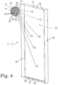
- the third barrier element 31 comprises a third surface 35 which is provided with one or more third through openings 32.
- each third opening 32 delimit a through area 33, i.e. a venting area 33 through which the hot gases, flames, particulates, coming from the inside of the enclosure can pass through; the various venting areas 33 defined by each of the one or more third openings 32 are equal to each other.
- the one or more third through openings 12 which delimit all a respective equal venting area 33 are randomly positioned on the third surface 35.
- the third barrier element 31 is constituted by a metallic plate which has a central side 35 suitably perforated so as to have the one or more, preferably a plurality of, third though openings 32, and a plurality of sides 36, 37.
- the third through openings 32 are constituted by circular through holes 32, with the front area of each circle forming the respective venting area 33 (an exemplary one of which is marked with points in the magnified portion (C)).
- third through openings of whatever shape provided it is compatible for the scope of the present invention, e.g. there can be squared through openings, or elliptic through openings, et cetera, delimiting each the same respective venting area 33.
- the barrier element 31 can be provided with other openings whose perimetrical rims may delimit a different through area; for example, some openings 38, 39 may be used just for receiving fixing screws, as well as to contribute to venting.
- the number of third through openings 32 defining each a respective same venting area 33 provided on the third surface 35 is preferably predominant, i.e. at least more than half the holes provided on the third surface 25 is constituted by the indicated third through openings 22.
- the third venting area 33 delimited by the rims of each third through opening 32 of the one or more third through openings 32 is different from at least one of the first venting area 13 of each first through opening 12 of the one or more first through openings 1.2 and the second venting area 23 defined by each second through opening 22 of the one or more second through openings 22.
- the first venting area 13 defined by each first through opening 12 of the set of one or more first through openings 12 is larger than the third venting area 33 delimited by the rims of each third through opening 32 of the set of one or more third through openings 22; more preferably, the third venting area 33 of each third through opening 32 of the one or more third through openings 32 is even smaller than the second venting area 23 defined by each second through opening 22 of the one or more second through openings 22.
- the third venting area 33 of each third through opening 32 of the set of one or more third through openings 22 is between 3% and 30% of the first venting area 13 defined by each first through opening 12 of the set of one or more first through openings 12.
- each circular third opening 32 has a diameter D 3 of 1,5 mm; hence, each first venting area 33 is equal to 1,76 mm 2 .
- the third barrier element 31 may be constituted by a full shaped plate, i.e. it is not perforated (apart from possible holes needed for fixing) in order to define one or more venting areas.
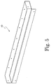
- the arc protection assembly 10 may preferably further comprise a lower cover 40 and an upper cover 50, exemplary embodiments of which are illustrated in figures 5 and 6 , respectively.
- the first barrier element 11 is positioned with the first surface 15 facing the first wall 1 provided with the opening(s) 7; preferably, the central side which forms the first surface 15 of the first barrier element 11 is fixed to the first wall 1 with its lateral sides 16, 17 protruding from the central side 15 away from the first wall 1.
- the lower cover 50 is positioned close to the bottom end of the first barrier element 11 and is fixed to the rear wall 1.
- the second barrier element 21 is positioned with the second surface 25 facing the first surface 15 so as the one or more second through openings 22 are at least partially off-set with respect to the one or more first through openings 12; preferably, the second barrier 21 is first connected to the upper cover 50 and then is positioned so as to surround the first barrier element 11 and with its central side forming the second surface 25 which faces the first surface 15 and with its lateral sides 26, 27 protruding towards and being connected to the rear wall 1 of the enclosure, by means of the folded rims 28.
- the third barrier element 31 is positioned with the third surface 35 facing the second surface 25 from the opposite side with respect to the first surface 15 and in such a way that the one or more third through openings 32 are at least partially off-set with respect to the one or more second through openings 22; preferably, the third barrier element 31 screwed to the other part of the assembly 10 from the opposite side with respect to the first barrier element 11 with reference to the second surface 25, with the sides 36, 37 substantially enclosing the corresponding parts of the barrier elements 11, 21 and the upper cover 50 as well.
- the arc protection assembly 10 defines an overall, substantially confined, interior space which receives the byproducts of an electric arc struck in the enclosure.
- the upper cover 50 and the lower cover 40 can be also used when the third barrier element 31 is not used, and therefore they may be likewise operatively connected, e.g. screwed, to the first and second barrier elements 11, 21 at the top and bottom ends thereof, respectively.
- the switchgear panel 100 offers an improved arc protection system with significant advantages over the known prior art and according to a solution extremely simple and effective.
- the assembly 10 defines, as a whole, a confined environment inside which the resulting effects of an electric arc are conveyed; then, the not perforated parts of each barrier element stop some of the arc-generated products, while the sets of first, second, and when used, third through openings, allow the passage of some other arc-generated products.
- the assembly 10 behaves like a suppressor, in particular as regard to hot gases and flames, which are extinguished inside the assembly 10 itself, or outside it at a short distance compatible with relevant safety standard requirements and tests.
- the electric switchgear panel 100 thus conceived may undergo numerous modifications and come in several variants, all falling within the scope of the inventive concept as defined by the appended claims; for the example, the various barrier elements may be differently shaped, or they may be differently positioned with respect to each other and to the associated enclosure, or differently connected; the assembly 10 can be connected to another wall of the enclosure, for instance the roof wall, et cetera.
- the component materials and dimensions of the switchgear may be of any type, according to needs and the state of the art and provided they are compatible with the scope of the invention as defined in the appended claims.
Landscapes
- Engineering & Computer Science (AREA)
- Power Engineering (AREA)
- Patch Boards (AREA)
- Switch Cases, Indication, And Locking (AREA)
- Distribution Board (AREA)
Claims (15)
- Schaltgerät-Panel (100), aufweisend:ein Gehäuse mit einer Mehrzahl an Wänden (1, 2, 3, 4, 5, 6), die ein Innenvolumen abgrenzen, das geeignet ist, eine entsprechende elektrische oder elektronische Ausrüstung aufzunehmen, wobei zumindest eine erste Wand (1) der Mehrzahl an Wänden mit einer oder mehreren Öffnungen (7) versehen ist, die geeignet sind, ein Entlüften außerhalb des Gehäuses von heißen Gasen, Flammen, Partikeln, die erzeugt werden, wenn ein Lichtbogen innerhalb des Panels (100) zündet, zu ermöglichen;dadurch gekennzeichnet, dass es Folgendes aufweist:eine Lichtbogenschutzbaugruppe (10), die außerhalb des Gehäuses positioniert ist und operativ zumindest der ersten Wand (1) zugeordnet ist, und zumindest ein erstes Barrierenelement (11) mit einer ersten Oberfläche (15) aufweist, das mit einer oder mehreren ersten Durchgangsöffnungen (12) versehen ist, die jeweils einen ersten Entlüftungsbereich (13) definieren, durch den die heißen Gase, Flammen, Partikel, die von innerhalb des Gehäuses kommen, hindurchströmen können, und ein zweites Barrierenelement (21) aufweist, das operativ dem ersten Barrierenelement (11) zugeordnet ist und eine zweite Oberfläche (25) aufweist, die mit einer oder mehreren zweiten Durchgangsöffnungen (22) versehen ist, die jeweils einen zweiten Entlüftungsbereich (23) definieren, durch den die heißen Gase, Flammen, Partikel, die von innerhalb des Gehäuses kommen und die die eine oder mehreren Öffnungen (7) und die ersten Öffnungen (12) bereits passiert haben, hindurchströmen können, wobei der erste Belüftungsbereich (13) jeder ersten Durchgangsöffnung (12) des einen oder der mehreren ersten Durchgangsöffnungen (12) von dem zweiten Entlüftungsbereich (23) der zweiten Durchgangsöffnung (22) von der einen oder den mehreren zweiten Durchgangsöffnungen (22) verschieden ist.
- Schaltgerät-Panel (100) nach Anspruch 1, dadurch gekennzeichnet, dass der erste Entlüftungsbereich (13), der durch jede erste Durchgangsöffnung (12) der einen oder mehreren ersten Durchgangsöffnungen (12) definiert ist, größer ist als der zweite Entlüftungsbereich (23) jeder zweiten Durchgangsöffnung (22) der einen oder mehreren zweiten Durchgangsöffnungen (22).
- Schaltgerät-Panel (100) nach Anspruch 2, dadurch gekennzeichnet, dass der zweite Entlüftungsbereich (23) jeder zweiten Durchgangsöffnung (22) von der einen oder den mehreren zweiten Durchgangsöffnungen (22) zwischen 5% und 50% des ersten Entlüftungsbereichs (13) einnimmt, der durch jede erste Durchgangsöffnung (12) von der einen oder den mehreren ersten Durchgangsöffnungen (12) definiert ist.
- Schaltgerät-Panel (100) nach einem oder mehreren der vorgenannten Ansprüche, dadurch gekennzeichnet, dass die eine oder die mehreren ersten Durchgangsöffnungen (12) zufällig auf der ersten Oberfläche (15) positioniert sind.
- Schaltgerät-Panel (100) nach einem oder mehreren der vorgenannten Ansprüche, dadurch gekennzeichnet, dass die eine oder die mehreren zweiten Durchgangsöffnungen (22) zufällig auf der zweiten Oberfläche (25) positioniert sind.
- Schaltgerät-Panel (100) nach einem oder mehreren der vorgenannten Ansprüche, dadurch gekennzeichnet, dass das erste Barrierenelement (11) so positioniert ist, dass die erste Oberfläche (15) der ersten Wand (1) zugewandt ist, und das zweite Barrierenelement (21) so positioniert ist, dass die zweite Oberfläche (25) der ersten Oberfläche (15) zugewandt ist, so dass die eine oder die mehreren zweiten Durchgangsöffnungen (22) im Hinblick auf die eine oder die mehreren ersten Durchgangsöffnungen (12) zumindest teilweise versetzt sind.
- Schaltgerät-Panel (100) nach einem oder mehreren der vorgenannten Ansprüche, dadurch gekennzeichnet, dass die Lichtbogenschutzbaugruppe (10) ein drittes Barrierenelement (31) aufweist, das zumindest einem von den ersten und zweiten Barrierenelementen (11 12) operativ zugeordnet ist.
- Schaltgerät-Panel (100) nach einem oder mehreren der vorgenannten Ansprüche, dadurch gekennzeichnet, dass das dritte Barrierenelement (31) eine dritte Oberfläche (35) aufweist, die über eine oder mehrere dritte Durchgangsöffnungen (32) verfügt, die jeweils einen dritten Entlüftungsbereich (33) definieren.
- Schaltgerät-Panel (100) nach Anspruch 8, dadurch gekennzeichnet, dass die eine oder die mehreren dritten Durchgangsöffnungen (32) zufällig auf der dritten Oberfläche (35) positioniert sind.
- Schaltgerät-Panel (100) nach Anspruch 8, dadurch gekennzeichnet, dass sich der dritte Entlüftungsbereich (33) jeder dritten Durchgangsöffnung (32) der einen oder der mehreren dritten Durchgangsöffnungen (32) von zumindest einem von dem ersten Entlüftungsbereich (12), der durch jede erste Durchgangsöffnung (12) von der einen oder den mehreren ersten Durchgangsöffnungen (12) definiert ist, und dem zweiten Entlüftungsbereich (23), der durch jede zweite Durchgangsöffnung (22) von der einen oder den mehreren zweiten Durchgangsöffnungen (22) definiert ist, unterscheidet.
- Schaltgerät-Panel (100) nach Anspruch 10, dadurch gekennzeichnet, dass der dritte Entlüftungsbereich (33) jeder dritten Durchgangsöffnung (32) der einen oder der mehreren dritten Durchgangsöffnungen (32) kleiner ist als der erste Entlüftungsbereich (13), der durch jede erste Durchgangsöffnung (12) der einen oder der mehreren ersten Durchgangsöffnungen (12) definiert ist.
- Schaltgerät-Panel (100) nach Anspruch 10, dadurch gekennzeichnet, dass der dritte Entlüftungsbereich (33) jeder dritten Durchgangsöffnung (32) der einen oder der mehreren dritten Durchgangsöffnungen (32) kleiner ist als der zweite Entlüftungsbereich (23), der durch jede zweite Durchgangsöffnung (22) der einen oder der mehreren zweiten Durchgangsöffnungen (22) definiert ist.
- Schaltgerät-Panel (100) nach einem oder mehreren der vorgenannten Ansprüche, dadurch gekennzeichnet, dass der dritte Entlüftungsbereich (33) jeder dritten Durchgangsöffnung (32) der einen oder mehreren dritten Durchgangsöffnungen (32) zwischen 3% und 30% des ersten Entlüftungsbereichs (13) ausmacht, der durch die erste Durchgangsöffnung (12) der einen oder der mehreren ersten Durchgangsöffnungen (12) definiert ist.
- Schaltgerät-Panel (100) nach einem oder mehreren der vorgenannten Ansprüche, dadurch gekennzeichnet, dass das dritte Barrierenelement (31) so positioniert ist, dass die dritte Oberfläche (35) der zweiten Oberfläche (25) von der gegenüberliegenden Seite im Verhältnis zu der ersten Oberfläche (15) zugewandt ist, und zwar so, dass die eine oder die mehreren dritten Durchgangsöffnungen (32) im Verhältnis zu der einen oder den mehreren zweiten Durchgangsöffnungen (22) zumindest teilweise versetzt sind.
- Schaltgerät-Panel (100) nach einem oder mehreren der vorgenannten Ansprüche, dadurch gekennzeichnet, dass das erste Barrierenelement (11) U-förmig ist, wobei seine mittige Seite, die die erste Oberfläche (15) bildet, die an der ersten Wand (1) und ihren seitlichen Seiten (16, 17) befestigt ist, von der mittigen Seite aus von der ersten Wand (1) weg hervorstehen, und wobei das zweite Barrierenelement (21) U-förmig ist und so positioniert ist, dass es das erste Barrierenelement (11) umgibt, wobei seine mittige Seite die zweite Oberfläche (25) bildet, und der ersten Oberfläche (15) zugewandt ist und ihre seitlichen Seiten (26, 27) in Richtung entsprechender Gehäusewände hervorsteht und mit ihnen verbunden ist, und wobei das dritte Barrierenelement (31) im Verhältnis zu der zweiten Oberfläche (25) von der gegenüberliegenden Seite aus im Verhältnis zu dem ersten Barrierenelement (11) positioniert ist, und wobei die Lichtbogenschutzbaugruppe (10) ferner eine obere Abdeckung (50) und eine untere Abdeckung (40) aufweist, die einem oder mehreren der ersten, zweiten, und dritten Barrierenelementen (11, 21, 31) operativ zugeordnet sind.
Priority Applications (4)
| Application Number | Priority Date | Filing Date | Title |
|---|---|---|---|
| ES10163878.1T ES2602463T3 (es) | 2010-05-26 | 2010-05-26 | Panel de conmutador eléctrico con ensamblaje de protección de arco mejorado |
| EP10163878.1A EP2390974B1 (de) | 2010-05-26 | 2010-05-26 | Elektrische Schalttafel mit verbesserter Bogenschutzanordnung |
| US13/109,834 US8748771B2 (en) | 2010-05-26 | 2011-05-17 | Electric switchgear panel with improved arc protection assembly |
| CN201110139795.0A CN102263380B (zh) | 2010-05-26 | 2011-05-24 | 具有改进的电弧保护组件的电开关装置面板 |
Applications Claiming Priority (1)
| Application Number | Priority Date | Filing Date | Title |
|---|---|---|---|
| EP10163878.1A EP2390974B1 (de) | 2010-05-26 | 2010-05-26 | Elektrische Schalttafel mit verbesserter Bogenschutzanordnung |
Publications (2)
| Publication Number | Publication Date |
|---|---|
| EP2390974A1 EP2390974A1 (de) | 2011-11-30 |
| EP2390974B1 true EP2390974B1 (de) | 2016-08-10 |
Family
ID=43014224
Family Applications (1)
| Application Number | Title | Priority Date | Filing Date |
|---|---|---|---|
| EP10163878.1A Active EP2390974B1 (de) | 2010-05-26 | 2010-05-26 | Elektrische Schalttafel mit verbesserter Bogenschutzanordnung |
Country Status (4)
| Country | Link |
|---|---|
| US (1) | US8748771B2 (de) |
| EP (1) | EP2390974B1 (de) |
| CN (1) | CN102263380B (de) |
| ES (1) | ES2602463T3 (de) |
Families Citing this family (7)
| Publication number | Priority date | Publication date | Assignee | Title |
|---|---|---|---|---|
| CN103200795A (zh) * | 2012-01-05 | 2013-07-10 | 通用电气公司 | 电力设备机壳和相关方法 |
| US8922977B2 (en) * | 2012-04-20 | 2014-12-30 | Schneider Electric USA, Inc. | Passive arc management system with a flue chamber |
| US9425591B2 (en) * | 2013-10-31 | 2016-08-23 | Schneider Electric Industries Sas | ARC deflecting and ventilation assembly for electrical enclosures and systems for ARC deflecting and ventilation |
| DE102017112159A1 (de) * | 2017-06-01 | 2018-12-06 | R. Stahl Schaltgeräte GmbH | Explosionssicheres Gehäuse mit innerer Druckentlastung |
| US10375843B2 (en) | 2017-06-06 | 2019-08-06 | Automatisation Grimard Inc. | Switchgear exhaust assembly |
| DE102018120877B4 (de) * | 2018-08-27 | 2021-09-30 | R.Stahl Schaltgeräte GmbH | Explosionsgeschütztes Gehäuse |
| DE102019113195B4 (de) * | 2019-05-17 | 2021-02-25 | R.Stahl Schaltgeräte GmbH | Explosionsgeschütztes Gehäuse |
Family Cites Families (15)
| Publication number | Priority date | Publication date | Assignee | Title |
|---|---|---|---|---|
| DE7232011U (de) | 1972-08-30 | 1972-11-23 | Bbc,Dt | Kapselungs und Schottungswand |
| SE430738B (sv) * | 1982-05-06 | 1983-12-05 | Asea Ab | Anordning vid en ventilationsoppning for en kapslad elektrisk kopplingsutrustning |
| DE8901423U1 (de) | 1989-02-08 | 1989-03-23 | SAN-Schaltanlagenbau GmbH & Co. KG, 8500 Nürnberg | Gehäuse zur Elektroinstallation in Gebäuden |
| US5767440A (en) | 1995-12-12 | 1998-06-16 | Square D Company | Protective enclosure for medium and high voltage circuit breakers |
| US5710402A (en) * | 1996-07-30 | 1998-01-20 | Abb Power T&D Company Inc. | Arc-resistant switchgear enclosure employing a toggle flap venting system |
| DE19811714C2 (de) * | 1998-03-18 | 2000-04-13 | Loh Kg Rittal Werk | Bausatz für einen Schaltschrank |
| US6407331B1 (en) * | 2001-03-21 | 2002-06-18 | Eaton Corporation | Pressure relief panel for arc resistant cabinets |
| US6417443B1 (en) * | 2001-03-29 | 2002-07-09 | Eaton Corporation | Exhaust chamber for arc resistant cabinets |
| JP2002291919A (ja) * | 2001-03-30 | 2002-10-08 | Nec Corp | 電子機器の防火方式 |
| AU2003277318A1 (en) * | 2002-10-11 | 2004-05-04 | S And C Electric Company | Switchgear with arc-resistant features |
| WO2008136113A1 (ja) * | 2007-04-26 | 2008-11-13 | Mitsubishi Electric Corporation | 金属閉鎖形スイッチギヤ |
| DE102007022363A1 (de) * | 2007-05-04 | 2008-11-06 | Siemens Ag | Schottvorrichtung für eine Stromverteilereinheit |
| US7821774B2 (en) * | 2008-02-12 | 2010-10-26 | Siemens Industry, Inc. | Mounting base with arc plenum |
| US8242395B2 (en) * | 2008-02-21 | 2012-08-14 | Siemens Industry, Inc. | Circuit breaker compartment arc flash venting system |
| US8375566B2 (en) * | 2011-02-28 | 2013-02-19 | Abb Inc. | Method of providing arc-resistant dry type transformer enclosure |
-
2010
- 2010-05-26 EP EP10163878.1A patent/EP2390974B1/de active Active
- 2010-05-26 ES ES10163878.1T patent/ES2602463T3/es active Active
-
2011
- 2011-05-17 US US13/109,834 patent/US8748771B2/en active Active
- 2011-05-24 CN CN201110139795.0A patent/CN102263380B/zh active Active
Also Published As
| Publication number | Publication date |
|---|---|
| US20110292575A1 (en) | 2011-12-01 |
| CN102263380B (zh) | 2015-11-25 |
| EP2390974A1 (de) | 2011-11-30 |
| US8748771B2 (en) | 2014-06-10 |
| CN102263380A (zh) | 2011-11-30 |
| ES2602463T3 (es) | 2017-02-21 |
Similar Documents
| Publication | Publication Date | Title |
|---|---|---|
| EP2390974B1 (de) | Elektrische Schalttafel mit verbesserter Bogenschutzanordnung | |
| US9117607B2 (en) | Muffler for enhanced arc protection | |
| US8733855B2 (en) | Arc resistant switchgear modular compartment for instrumentation and circuit breakers | |
| US20140118887A1 (en) | Plenum assembly | |
| CN108292830B (zh) | 气体绝缘开关装置 | |
| EP2472683B1 (de) | Vorrichtung und Verfahren für den Schaltungsschutz | |
| JP2012143136A (ja) | 機器エンクロージャ内の回路保護用のシステムおよび装置 | |
| EP2501001B1 (de) | Elektrische Schaltanlage mit Gasgkühlanordnung | |
| US8279573B2 (en) | Circuit protection device and system | |
| US10784660B1 (en) | Enhancing an auxiliary compartment of a modular bucket assembly in an arc resistant switchgear | |
| US11159000B2 (en) | Front connected switchgear assembly having an integrated arc flash venting system | |
| KR100583791B1 (ko) | 고집적형 폐쇄수전반 | |
| EP2408076A1 (de) | Elektrische Schaltgerätefläche mit verbessertem Lichtbogenerkennungssystem und entsprechendes Lichtbogenerkennungsverfahren | |
| EP2515399A1 (de) | Schutzfilteranordnung für eine Schalttafel und Schalttafel damit | |
| KR101237875B1 (ko) | 일체형 수배전반 | |
| US9429312B2 (en) | Component for electric power system and method of determining whether a power circuit in an electric power system is open or closed | |
| CN103872612A (zh) | 用于避免地闪击的电弧减轻组件和组装方法 | |
| KR200398674Y1 (ko) | 고집적형 폐쇄수전반 | |
| KR100573023B1 (ko) | 배전반의 콘트롤 엔클로저 | |
| Kumpulainen | Aspects and directions of internal arc protectio | |
| KR20190017693A (ko) | 아크방출기능이 강화된 고압 배전반 외함장치 | |
| Kay | Considerations for installing and applying arc resistant low and medium voltage control equipment in forest products industries | |
| Bugaris et al. | Arc resistant equipment for low voltage motor control center applications |
Legal Events
| Date | Code | Title | Description |
|---|---|---|---|
| AK | Designated contracting states |
Kind code of ref document: A1 Designated state(s): AL AT BE BG CH CY CZ DE DK EE ES FI FR GB GR HR HU IE IS IT LI LT LU LV MC MK MT NL NO PL PT RO SE SI SK SM TR |
|
| AX | Request for extension of the european patent |
Extension state: BA ME RS |
|
| PUAI | Public reference made under article 153(3) epc to a published international application that has entered the european phase |
Free format text: ORIGINAL CODE: 0009012 |
|
| 17P | Request for examination filed |
Effective date: 20120524 |
|
| GRAP | Despatch of communication of intention to grant a patent |
Free format text: ORIGINAL CODE: EPIDOSNIGR1 |
|
| RIC1 | Information provided on ipc code assigned before grant |
Ipc: H02B 13/025 20060101AFI20160129BHEP |
|
| INTG | Intention to grant announced |
Effective date: 20160308 |
|
| GRAS | Grant fee paid |
Free format text: ORIGINAL CODE: EPIDOSNIGR3 |
|
| GRAA | (expected) grant |
Free format text: ORIGINAL CODE: 0009210 |
|
| AK | Designated contracting states |
Kind code of ref document: B1 Designated state(s): AL AT BE BG CH CY CZ DE DK EE ES FI FR GB GR HR HU IE IS IT LI LT LU LV MC MK MT NL NO PL PT RO SE SI SK SM TR |
|
| REG | Reference to a national code |
Ref country code: GB Ref legal event code: FG4D |
|
| REG | Reference to a national code |
Ref country code: CH Ref legal event code: EP Ref country code: AT Ref legal event code: REF Ref document number: 819797 Country of ref document: AT Kind code of ref document: T Effective date: 20160815 |
|
| REG | Reference to a national code |
Ref country code: IE Ref legal event code: FG4D |
|
| REG | Reference to a national code |
Ref country code: DE Ref legal event code: R096 Ref document number: 602010035286 Country of ref document: DE |
|
| REG | Reference to a national code |
Ref country code: DE Ref legal event code: R081 Ref document number: 602010035286 Country of ref document: DE Owner name: ABB SCHWEIZ AG, CH Free format text: FORMER OWNER: ABB TECHNOLOGY AG, ZUERICH, CH Ref country code: DE Ref legal event code: R082 Ref document number: 602010035286 Country of ref document: DE Representative=s name: KUHNEN & WACKER PATENT- UND RECHTSANWALTSBUERO, DE |
|
| RAP2 | Party data changed (patent owner data changed or rights of a patent transferred) |
Owner name: ABB SCHWEIZ AG |
|
| REG | Reference to a national code |
Ref country code: LT Ref legal event code: MG4D |
|
| REG | Reference to a national code |
Ref country code: NL Ref legal event code: MP Effective date: 20160810 |
|
| REG | Reference to a national code |
Ref country code: NO Ref legal event code: T2 Effective date: 20160810 |
|
| REG | Reference to a national code |
Ref country code: AT Ref legal event code: MK05 Ref document number: 819797 Country of ref document: AT Kind code of ref document: T Effective date: 20160810 |
|
| PG25 | Lapsed in a contracting state [announced via postgrant information from national office to epo] |
Ref country code: LT Free format text: LAPSE BECAUSE OF FAILURE TO SUBMIT A TRANSLATION OF THE DESCRIPTION OR TO PAY THE FEE WITHIN THE PRESCRIBED TIME-LIMIT Effective date: 20160810 Ref country code: HR Free format text: LAPSE BECAUSE OF FAILURE TO SUBMIT A TRANSLATION OF THE DESCRIPTION OR TO PAY THE FEE WITHIN THE PRESCRIBED TIME-LIMIT Effective date: 20160810 Ref country code: IS Free format text: LAPSE BECAUSE OF FAILURE TO SUBMIT A TRANSLATION OF THE DESCRIPTION OR TO PAY THE FEE WITHIN THE PRESCRIBED TIME-LIMIT Effective date: 20161210 Ref country code: NL Free format text: LAPSE BECAUSE OF FAILURE TO SUBMIT A TRANSLATION OF THE DESCRIPTION OR TO PAY THE FEE WITHIN THE PRESCRIBED TIME-LIMIT Effective date: 20160810 |
|
| REG | Reference to a national code |
Ref country code: NO Ref legal event code: CREP Representative=s name: ZACCO NORWAY AS, POSTBOKS 2003 VIKA, 0125 OSLO |
|
| REG | Reference to a national code |
Ref country code: ES Ref legal event code: FG2A Ref document number: 2602463 Country of ref document: ES Kind code of ref document: T3 Effective date: 20170221 |
|
| PG25 | Lapsed in a contracting state [announced via postgrant information from national office to epo] |
Ref country code: GR Free format text: LAPSE BECAUSE OF FAILURE TO SUBMIT A TRANSLATION OF THE DESCRIPTION OR TO PAY THE FEE WITHIN THE PRESCRIBED TIME-LIMIT Effective date: 20161111 Ref country code: AT Free format text: LAPSE BECAUSE OF FAILURE TO SUBMIT A TRANSLATION OF THE DESCRIPTION OR TO PAY THE FEE WITHIN THE PRESCRIBED TIME-LIMIT Effective date: 20160810 Ref country code: LV Free format text: LAPSE BECAUSE OF FAILURE TO SUBMIT A TRANSLATION OF THE DESCRIPTION OR TO PAY THE FEE WITHIN THE PRESCRIBED TIME-LIMIT Effective date: 20160810 Ref country code: PL Free format text: LAPSE BECAUSE OF FAILURE TO SUBMIT A TRANSLATION OF THE DESCRIPTION OR TO PAY THE FEE WITHIN THE PRESCRIBED TIME-LIMIT Effective date: 20160810 Ref country code: SE Free format text: LAPSE BECAUSE OF FAILURE TO SUBMIT A TRANSLATION OF THE DESCRIPTION OR TO PAY THE FEE WITHIN THE PRESCRIBED TIME-LIMIT Effective date: 20160810 Ref country code: PT Free format text: LAPSE BECAUSE OF FAILURE TO SUBMIT A TRANSLATION OF THE DESCRIPTION OR TO PAY THE FEE WITHIN THE PRESCRIBED TIME-LIMIT Effective date: 20161212 |
|
| PG25 | Lapsed in a contracting state [announced via postgrant information from national office to epo] |
Ref country code: EE Free format text: LAPSE BECAUSE OF FAILURE TO SUBMIT A TRANSLATION OF THE DESCRIPTION OR TO PAY THE FEE WITHIN THE PRESCRIBED TIME-LIMIT Effective date: 20160810 Ref country code: RO Free format text: LAPSE BECAUSE OF FAILURE TO SUBMIT A TRANSLATION OF THE DESCRIPTION OR TO PAY THE FEE WITHIN THE PRESCRIBED TIME-LIMIT Effective date: 20160810 |
|
| REG | Reference to a national code |
Ref country code: DE Ref legal event code: R097 Ref document number: 602010035286 Country of ref document: DE |
|
| REG | Reference to a national code |
Ref country code: FR Ref legal event code: PLFP Year of fee payment: 8 |
|
| PG25 | Lapsed in a contracting state [announced via postgrant information from national office to epo] |
Ref country code: CZ Free format text: LAPSE BECAUSE OF FAILURE TO SUBMIT A TRANSLATION OF THE DESCRIPTION OR TO PAY THE FEE WITHIN THE PRESCRIBED TIME-LIMIT Effective date: 20160810 Ref country code: SK Free format text: LAPSE BECAUSE OF FAILURE TO SUBMIT A TRANSLATION OF THE DESCRIPTION OR TO PAY THE FEE WITHIN THE PRESCRIBED TIME-LIMIT Effective date: 20160810 Ref country code: BG Free format text: LAPSE BECAUSE OF FAILURE TO SUBMIT A TRANSLATION OF THE DESCRIPTION OR TO PAY THE FEE WITHIN THE PRESCRIBED TIME-LIMIT Effective date: 20161110 Ref country code: DK Free format text: LAPSE BECAUSE OF FAILURE TO SUBMIT A TRANSLATION OF THE DESCRIPTION OR TO PAY THE FEE WITHIN THE PRESCRIBED TIME-LIMIT Effective date: 20160810 Ref country code: SM Free format text: LAPSE BECAUSE OF FAILURE TO SUBMIT A TRANSLATION OF THE DESCRIPTION OR TO PAY THE FEE WITHIN THE PRESCRIBED TIME-LIMIT Effective date: 20160810 |
|
| PLBE | No opposition filed within time limit |
Free format text: ORIGINAL CODE: 0009261 |
|
| STAA | Information on the status of an ep patent application or granted ep patent |
Free format text: STATUS: NO OPPOSITION FILED WITHIN TIME LIMIT |
|
| 26N | No opposition filed |
Effective date: 20170511 |
|
| PG25 | Lapsed in a contracting state [announced via postgrant information from national office to epo] |
Ref country code: LU Free format text: LAPSE BECAUSE OF NON-PAYMENT OF DUE FEES Effective date: 20170531 Ref country code: SI Free format text: LAPSE BECAUSE OF FAILURE TO SUBMIT A TRANSLATION OF THE DESCRIPTION OR TO PAY THE FEE WITHIN THE PRESCRIBED TIME-LIMIT Effective date: 20160810 |
|
| GBPC | Gb: european patent ceased through non-payment of renewal fee |
Effective date: 20170526 |
|
| PG25 | Lapsed in a contracting state [announced via postgrant information from national office to epo] |
Ref country code: MC Free format text: LAPSE BECAUSE OF FAILURE TO SUBMIT A TRANSLATION OF THE DESCRIPTION OR TO PAY THE FEE WITHIN THE PRESCRIBED TIME-LIMIT Effective date: 20160810 |
|
| REG | Reference to a national code |
Ref country code: CH Ref legal event code: PFUS Owner name: ABB SCHWEIZ AG, CH Free format text: FORMER OWNER: ABB TECHNOLOGY AG, CH |
|
| REG | Reference to a national code |
Ref country code: IE Ref legal event code: MM4A |
|
| PG25 | Lapsed in a contracting state [announced via postgrant information from national office to epo] |
Ref country code: LU Free format text: LAPSE BECAUSE OF NON-PAYMENT OF DUE FEES Effective date: 20170526 |
|
| PG25 | Lapsed in a contracting state [announced via postgrant information from national office to epo] |
Ref country code: GB Free format text: LAPSE BECAUSE OF NON-PAYMENT OF DUE FEES Effective date: 20170526 Ref country code: IE Free format text: LAPSE BECAUSE OF NON-PAYMENT OF DUE FEES Effective date: 20170526 |
|
| REG | Reference to a national code |
Ref country code: FR Ref legal event code: PLFP Year of fee payment: 9 |
|
| PG25 | Lapsed in a contracting state [announced via postgrant information from national office to epo] |
Ref country code: MT Free format text: LAPSE BECAUSE OF NON-PAYMENT OF DUE FEES Effective date: 20170526 |
|
| PG25 | Lapsed in a contracting state [announced via postgrant information from national office to epo] |
Ref country code: AL Free format text: LAPSE BECAUSE OF FAILURE TO SUBMIT A TRANSLATION OF THE DESCRIPTION OR TO PAY THE FEE WITHIN THE PRESCRIBED TIME-LIMIT Effective date: 20160810 |
|
| PG25 | Lapsed in a contracting state [announced via postgrant information from national office to epo] |
Ref country code: HU Free format text: LAPSE BECAUSE OF FAILURE TO SUBMIT A TRANSLATION OF THE DESCRIPTION OR TO PAY THE FEE WITHIN THE PRESCRIBED TIME-LIMIT; INVALID AB INITIO Effective date: 20100526 |
|
| PG25 | Lapsed in a contracting state [announced via postgrant information from national office to epo] |
Ref country code: CY Free format text: LAPSE BECAUSE OF NON-PAYMENT OF DUE FEES Effective date: 20160810 |
|
| PG25 | Lapsed in a contracting state [announced via postgrant information from national office to epo] |
Ref country code: MK Free format text: LAPSE BECAUSE OF FAILURE TO SUBMIT A TRANSLATION OF THE DESCRIPTION OR TO PAY THE FEE WITHIN THE PRESCRIBED TIME-LIMIT Effective date: 20160810 |
|
| PG25 | Lapsed in a contracting state [announced via postgrant information from national office to epo] |
Ref country code: TR Free format text: LAPSE BECAUSE OF FAILURE TO SUBMIT A TRANSLATION OF THE DESCRIPTION OR TO PAY THE FEE WITHIN THE PRESCRIBED TIME-LIMIT Effective date: 20160810 |
|
| PGFP | Annual fee paid to national office [announced via postgrant information from national office to epo] |
Ref country code: FI Payment date: 20250526 Year of fee payment: 16 |
|
| PGFP | Annual fee paid to national office [announced via postgrant information from national office to epo] |
Ref country code: DE Payment date: 20250521 Year of fee payment: 16 |
|
| PGFP | Annual fee paid to national office [announced via postgrant information from national office to epo] |
Ref country code: ES Payment date: 20250627 Year of fee payment: 16 |
|
| PGFP | Annual fee paid to national office [announced via postgrant information from national office to epo] |
Ref country code: NO Payment date: 20250523 Year of fee payment: 16 |
|
| PGFP | Annual fee paid to national office [announced via postgrant information from national office to epo] |
Ref country code: BE Payment date: 20250521 Year of fee payment: 16 Ref country code: IT Payment date: 20250527 Year of fee payment: 16 |
|
| PGFP | Annual fee paid to national office [announced via postgrant information from national office to epo] |
Ref country code: FR Payment date: 20250528 Year of fee payment: 16 |
|
| PGFP | Annual fee paid to national office [announced via postgrant information from national office to epo] |
Ref country code: CH Payment date: 20250601 Year of fee payment: 16 |