EP2390976A2 - Élément de support pour assemblage des câbles, conduits ou tuyaux - Google Patents
Élément de support pour assemblage des câbles, conduits ou tuyaux Download PDFInfo
- Publication number
- EP2390976A2 EP2390976A2 EP11004974A EP11004974A EP2390976A2 EP 2390976 A2 EP2390976 A2 EP 2390976A2 EP 11004974 A EP11004974 A EP 11004974A EP 11004974 A EP11004974 A EP 11004974A EP 2390976 A2 EP2390976 A2 EP 2390976A2
- Authority
- EP
- European Patent Office
- Prior art keywords
- support member
- solids
- interlocking
- motion
- flexible material
- Prior art date
- Legal status (The legal status is an assumption and is not a legal conclusion. Google has not performed a legal analysis and makes no representation as to the accuracy of the status listed.)
- Ceased
Links
- 239000004020 conductor Substances 0.000 title claims abstract description 24
- 239000000463 material Substances 0.000 claims abstract description 246
- 239000007787 solid Substances 0.000 claims abstract description 165
- 239000010935 stainless steel Substances 0.000 claims description 38
- 229910001220 stainless steel Inorganic materials 0.000 claims description 38
- -1 polytetrafluoroethylene Polymers 0.000 claims description 37
- 229920001343 polytetrafluoroethylene Polymers 0.000 claims description 29
- 239000004810 polytetrafluoroethylene Substances 0.000 claims description 29
- 239000007769 metal material Substances 0.000 claims description 15
- 239000002131 composite material Substances 0.000 claims description 10
- 229920006231 aramid fiber Polymers 0.000 claims description 8
- JOYRKODLDBILNP-UHFFFAOYSA-N Ethyl urethane Chemical compound CCOC(N)=O JOYRKODLDBILNP-UHFFFAOYSA-N 0.000 claims description 6
- 230000000712 assembly Effects 0.000 abstract description 16
- 238000000429 assembly Methods 0.000 abstract description 16
- 239000007789 gas Substances 0.000 abstract description 6
- 239000007788 liquid Substances 0.000 abstract description 2
- 238000000034 method Methods 0.000 description 31
- 239000000835 fiber Substances 0.000 description 22
- 238000000465 moulding Methods 0.000 description 19
- 229920000106 Liquid crystal polymer Polymers 0.000 description 17
- 239000004977 Liquid-crystal polymers (LCPs) Substances 0.000 description 17
- 238000005452 bending Methods 0.000 description 14
- 238000001125 extrusion Methods 0.000 description 14
- 230000003014 reinforcing effect Effects 0.000 description 14
- 238000004519 manufacturing process Methods 0.000 description 11
- 238000010276 construction Methods 0.000 description 9
- 229920000642 polymer Polymers 0.000 description 7
- 229920006099 Vestamid® Polymers 0.000 description 6
- 229910045601 alloy Inorganic materials 0.000 description 6
- 239000000956 alloy Substances 0.000 description 6
- 229920000271 Kevlar® Polymers 0.000 description 5
- PXHVJJICTQNCMI-UHFFFAOYSA-N Nickel Chemical compound [Ni] PXHVJJICTQNCMI-UHFFFAOYSA-N 0.000 description 4
- 230000006835 compression Effects 0.000 description 4
- 238000007906 compression Methods 0.000 description 4
- 238000005516 engineering process Methods 0.000 description 4
- 239000012530 fluid Substances 0.000 description 4
- 238000003475 lamination Methods 0.000 description 4
- 229920001778 nylon Polymers 0.000 description 4
- 229920002725 thermoplastic elastomer Polymers 0.000 description 4
- 239000004677 Nylon Substances 0.000 description 3
- 239000004760 aramid Substances 0.000 description 3
- HJJVPARKXDDIQD-UHFFFAOYSA-N bromuconazole Chemical compound ClC1=CC(Cl)=CC=C1C1(CN2N=CN=C2)OCC(Br)C1 HJJVPARKXDDIQD-UHFFFAOYSA-N 0.000 description 3
- 229920000840 ethylene tetrafluoroethylene copolymer Polymers 0.000 description 3
- 229920002313 fluoropolymer Polymers 0.000 description 3
- 239000004811 fluoropolymer Substances 0.000 description 3
- 238000002347 injection Methods 0.000 description 3
- 239000007924 injection Substances 0.000 description 3
- 229910052751 metal Inorganic materials 0.000 description 3
- 239000002184 metal Substances 0.000 description 3
- 150000002739 metals Chemical class 0.000 description 3
- 230000003287 optical effect Effects 0.000 description 3
- 229920002647 polyamide Polymers 0.000 description 3
- 229920000728 polyester Polymers 0.000 description 3
- 229920000573 polyethylene Polymers 0.000 description 3
- 229920003369 Kevlar® 49 Polymers 0.000 description 2
- FYYHWMGAXLPEAU-UHFFFAOYSA-N Magnesium Chemical compound [Mg] FYYHWMGAXLPEAU-UHFFFAOYSA-N 0.000 description 2
- 229910000990 Ni alloy Inorganic materials 0.000 description 2
- 239000004696 Poly ether ether ketone Substances 0.000 description 2
- 239000004698 Polyethylene Substances 0.000 description 2
- 239000004743 Polypropylene Substances 0.000 description 2
- 239000004793 Polystyrene Substances 0.000 description 2
- 229910001069 Ti alloy Inorganic materials 0.000 description 2
- HCHKCACWOHOZIP-UHFFFAOYSA-N Zinc Chemical compound [Zn] HCHKCACWOHOZIP-UHFFFAOYSA-N 0.000 description 2
- 239000004676 acrylonitrile butadiene styrene Substances 0.000 description 2
- 238000004026 adhesive bonding Methods 0.000 description 2
- 229910052782 aluminium Inorganic materials 0.000 description 2
- XAGFODPZIPBFFR-UHFFFAOYSA-N aluminium Chemical compound [Al] XAGFODPZIPBFFR-UHFFFAOYSA-N 0.000 description 2
- 229910052749 magnesium Inorganic materials 0.000 description 2
- 239000011777 magnesium Substances 0.000 description 2
- 229920002530 polyetherether ketone Polymers 0.000 description 2
- 229920001155 polypropylene Polymers 0.000 description 2
- 229920002223 polystyrene Polymers 0.000 description 2
- 229920002635 polyurethane Polymers 0.000 description 2
- 239000004814 polyurethane Substances 0.000 description 2
- 239000004800 polyvinyl chloride Substances 0.000 description 2
- 238000002360 preparation method Methods 0.000 description 2
- 229920005989 resin Polymers 0.000 description 2
- 239000011347 resin Substances 0.000 description 2
- 238000007665 sagging Methods 0.000 description 2
- 239000004065 semiconductor Substances 0.000 description 2
- 229920001169 thermoplastic Polymers 0.000 description 2
- 229920006345 thermoplastic polyamide Polymers 0.000 description 2
- 239000004416 thermosoftening plastic Substances 0.000 description 2
- 229910052725 zinc Inorganic materials 0.000 description 2
- 239000011701 zinc Substances 0.000 description 2
- 229910001369 Brass Inorganic materials 0.000 description 1
- 229910000975 Carbon steel Inorganic materials 0.000 description 1
- RYGMFSIKBFXOCR-UHFFFAOYSA-N Copper Chemical compound [Cu] RYGMFSIKBFXOCR-UHFFFAOYSA-N 0.000 description 1
- 239000004593 Epoxy Substances 0.000 description 1
- KRHYYFGTRYWZRS-UHFFFAOYSA-M Fluoride anion Chemical compound [F-] KRHYYFGTRYWZRS-UHFFFAOYSA-M 0.000 description 1
- 229910000639 Spring steel Inorganic materials 0.000 description 1
- 229920006355 Tefzel Polymers 0.000 description 1
- 238000005299 abrasion Methods 0.000 description 1
- 230000001133 acceleration Effects 0.000 description 1
- 239000000853 adhesive Substances 0.000 description 1
- 230000001070 adhesive effect Effects 0.000 description 1
- 229920003235 aromatic polyamide Polymers 0.000 description 1
- 239000010951 brass Substances 0.000 description 1
- 239000010962 carbon steel Substances 0.000 description 1
- 238000005266 casting Methods 0.000 description 1
- 230000001010 compromised effect Effects 0.000 description 1
- 238000011109 contamination Methods 0.000 description 1
- 229920001577 copolymer Polymers 0.000 description 1
- 229910052802 copper Inorganic materials 0.000 description 1
- 239000010949 copper Substances 0.000 description 1
- 230000003247 decreasing effect Effects 0.000 description 1
- 229920001971 elastomer Polymers 0.000 description 1
- 239000000806 elastomer Substances 0.000 description 1
- 230000005611 electricity Effects 0.000 description 1
- QHSJIZLJUFMIFP-UHFFFAOYSA-N ethene;1,1,2,2-tetrafluoroethene Chemical compound C=C.FC(F)=C(F)F QHSJIZLJUFMIFP-UHFFFAOYSA-N 0.000 description 1
- 125000000816 ethylene group Chemical group [H]C([H])([*:1])C([H])([H])[*:2] 0.000 description 1
- 239000011152 fibreglass Substances 0.000 description 1
- 238000005242 forging Methods 0.000 description 1
- 239000011521 glass Substances 0.000 description 1
- 238000010348 incorporation Methods 0.000 description 1
- 238000007689 inspection Methods 0.000 description 1
- 238000010030 laminating Methods 0.000 description 1
- 239000000314 lubricant Substances 0.000 description 1
- 229920003052 natural elastomer Polymers 0.000 description 1
- 229920001194 natural rubber Polymers 0.000 description 1
- 239000002245 particle Substances 0.000 description 1
- 230000037361 pathway Effects 0.000 description 1
- 239000011295 pitch Substances 0.000 description 1
- 229920000927 poly(p-phenylene benzobisoxazole) Polymers 0.000 description 1
- 229920002577 polybenzoxazole Polymers 0.000 description 1
- 229920000098 polyolefin Polymers 0.000 description 1
- 229920000915 polyvinyl chloride Polymers 0.000 description 1
- 230000002787 reinforcement Effects 0.000 description 1
- 229920003031 santoprene Polymers 0.000 description 1
- 239000000126 substance Substances 0.000 description 1
- 229920003051 synthetic elastomer Polymers 0.000 description 1
- 239000005061 synthetic rubber Substances 0.000 description 1
- 238000012360 testing method Methods 0.000 description 1
- 239000012815 thermoplastic material Substances 0.000 description 1
- 229920001187 thermosetting polymer Polymers 0.000 description 1
- 239000010409 thin film Substances 0.000 description 1
- 239000002759 woven fabric Substances 0.000 description 1
Images






Classifications
-
- H—ELECTRICITY
- H02—GENERATION; CONVERSION OR DISTRIBUTION OF ELECTRIC POWER
- H02G—INSTALLATION OF ELECTRIC CABLES OR LINES, OR OF COMBINED OPTICAL AND ELECTRIC CABLES OR LINES
- H02G3/00—Installations of electric cables or lines or protective tubing therefor in or on buildings, equivalent structures or vehicles
- H02G3/02—Details
- H02G3/04—Protective tubing or conduits, e.g. cable ladders or cable troughs
- H02G3/0462—Tubings, i.e. having a closed section
- H02G3/0475—Tubings, i.e. having a closed section formed by a succession of articulated units
-
- F—MECHANICAL ENGINEERING; LIGHTING; HEATING; WEAPONS; BLASTING
- F16—ENGINEERING ELEMENTS AND UNITS; GENERAL MEASURES FOR PRODUCING AND MAINTAINING EFFECTIVE FUNCTIONING OF MACHINES OR INSTALLATIONS; THERMAL INSULATION IN GENERAL
- F16G—BELTS, CABLES, OR ROPES, PREDOMINANTLY USED FOR DRIVING PURPOSES; CHAINS; FITTINGS PREDOMINANTLY USED THEREFOR
- F16G13/00—Chains
- F16G13/12—Hauling- or hoisting-chains so called ornamental chains
- F16G13/16—Hauling- or hoisting-chains so called ornamental chains with arrangements for holding electric cables, hoses, or the like
-
- H—ELECTRICITY
- H02—GENERATION; CONVERSION OR DISTRIBUTION OF ELECTRIC POWER
- H02G—INSTALLATION OF ELECTRIC CABLES OR LINES, OR OF COMBINED OPTICAL AND ELECTRIC CABLES OR LINES
- H02G11/00—Arrangements of electric cables or lines between relatively-movable parts
- H02G11/006—Arrangements of electric cables or lines between relatively-movable parts using extensible carrier for the cable, e.g. self-coiling spring
Definitions
- the present invention relates to the field of mechanical supports.
- the invention is directed to mechanical supports for use with conductors designed to transmit electromagnetic energy and/or conduits that carry gases or fluids.
- the mechanical supports provide a wide range of motion in one direction arid a limited range of motion in an opposite direction.
- the invention is also directed to assemblies incorporating the mechanical supports.
- Cable tracks are made of a linear series of interlocking segments that partially surround and cradle a group of conductors or conduits.
- the interlocking segments often have surface features that interact to confine the range of motion of the cable tracks and the associated conductors or conduits in order to prevent excessive bending or kinking of the conductors or conduits.
- the motion of a cable track ranges between a flattened configuration and a configuration that curves in only one direction.
- Cable tracks are limited in many applications by their bulky size, weight, large bend radius, mechanical vibration, power consumption, and rapid wear. In some applications, such as manufacturing in a clean room environment, wear of the cable track material often produces particulates that contaminate the work area or work product.
- European Patent No. 528,141 to Elocab Sonderschreib GmbH & Co. teaches the incorporation of a cable track-like support element into a cable assembly.
- the support element is made of a linear chain of interlocking segments with surface features that contact and limit the relative motion of adjacent segments.
- the support element is placed between two or more parallel electrical or optical conductors.
- An "enveloping casing" Is extruded over the combination to form the finished cable assembly.
- the support element in the Elocab Sonderffy assembly suffers from wear between contact surfaces of the interlocking segments of the support elements. As the contact surfaces wear; the joints connecting the segments together loosen and allow the support element to sag. Once sagging occurs, the support element can buckle and cause the useful life of the support element to rapidly decrease. At high acceleration rates, sagging can cause the support element to buckle, further decreasing the useful life of the support element.
- Elocab Sonderffy assembly shares with conventional cable tracks
- the operation of Elocab Sonderffy assembly is further limited by the methods and materials used to construct the assembly.
- the enveloping jacket is extruded over the support element and associated electrical conductors.
- the use of an extrusion method to form the enveloping jacket limits the types of materials that can be used to form the jacket.
- the types of materials that are suitable for extrusion of the enveloping jacket can reduce the flexibility, range of motion, and useful life of the assembly.
- the support member would not use interlocking segments. Rather, the support member would be made of a length of flexible material with a series of non-interlocking motion-limiting elements attached to the flexible material. The support member would have a wide range of motion in one direction and essentially no range of motion in an opposite direction. The support member would be easy to manufacture and incorporate into an assembly of conductors or conduits. Such a supported cable assembly would be particularly useful with machines that perform rapid and precise mechanical movements over long periods of time. In manufacturing applications requiring a clean environment, the supported cable assembly could be provided with an external jacket that would generate very few particulates during use.
- the present invention is directed to support members for various types of assemblies such as electrical or optical cable assemblies, fluid or gas transporting assemblies, and assemblies having electrical shielding.
- the invention is also-directed to assemblies incorporating the support member.
- the invention is particularly useful with high speed, high accuracy machinery involved in precision manufacturing, testing, and inspection.
- individual movements of manufacturing machinery can be as small as a few nanometers in distance.
- conventional cable track supports and cable assemblies such mechanical precision can be severely compromised by vibrations and other mechanical noise generated by the supports and their associated assemblies.
- the size and bulk of conventional cable supports and assemblies can also limit the flexibility, speed, and power requirements of the manufacturing equipment. Contamination of a work space or work piece with particulates produced by conventional supports and assemblies is another problem often encountered in precision manufacturing.
- the present invention addresses these concerns by providing a lightweight support member with a high degree of flexibility, low mechanical noise, a small bend radius, long service life, and essentially no particulation.
- the support members are constructed of a series of non-interlocking, motion-limiting, elements attached to a length of flexible material.
- the resulting support members have a wide range of motion in one direction and essentially no range of motion in an opposite direction.
- the support member can support its own weight when extended a distance of a meter or more. In many embodiments, the support member can also support the weight of an assembly over a distance of about one-half meter or more.
- the support members are easily manufactured into an assembly by placing one or more support members substantially in parallel with at leavi one conductor or conduit and enclosing the combination in a polymeric material.
- the polymeric material is preferably applied to the combination with a lamination process as a means of controlling the thickness of the applied polymeric material.
- Lamination permits more flexible polymeric materials to be used to enclose the combination than those available with extrusion processes. Flexible polymeric materials do not limit the range of motion of the enclosed combination to the same degree as extruded materials. In addition to flexibility, preferred polymeric materials do not readily abrade, particulate, or wear out prematurely. Lamination is also preferred because it usually requires smaller amounts of polymeric material than extrusion processes. Each of these features contributes to the performance of the assembly.
- the present invention is a support member having a range of motion in one direction and essentially no range of motion in an opposite direction, said support member comprising a length of flexible material, and a plurality of non-interlocking solids attached to said flexible material, wherein adjacent non-interlocking solids have portions that contact one another and restrict bending of said flexible material in one direction of movement, and wherein said portions of said non-interlocking solids separate from one another when said flexible material is activated in an opposite direction of movement, thereby permitting said flexible material to bend and assume a curved configuration.
- the present invention is a support member for an assembly having a range of motion in one direction and essentially no range of motion in an opposite direction, said support member comprising a length of flexible material, a plurality of non-interlocking solids attached to said flexible material, and at least one filament attached to said plurality of non-interlocking solids, wherein said at least one filament restricts motion of said flexible material In one direction of movement, and wherein said at least one filament does not restrict motion of said flexible material in an opposite direction of movement, thereby permitting said flexible material to bend and assume a curved configuration.
- the present invention is directed to flexible support members capable of supporting themselves and an assembly of conductors, conduits, channels, or other components incorporating the support member.
- the support member and associated assemblies alternate between a straightened configuration and a configuration that curves, or arcs, in a single direction.
- the invention In the straightened configuration, the invention can be extended for a meter or more with essentially no bending or flexing of the support member.
- the invention In the curved configuration, the invention is very flexible and readily assumes a wide range of bend radii.
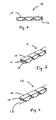
- the support member of the present invention is made of a length of flexible material (12) with a series of non-interlocking, motion-limiting, elements (14) attached to the flexible material ( Figures 1-7 ).
- the flexible material is preferably a narrow strip or similar piece of material having a uniform width and thickness.
- the flexible material is flat with a perimeter substantially in the shape of a rectangle.
- the flexible material can have a cross-section in the form of a square, rectangular, circular, elliptical, ovoid, or other shape and be solid or hollow along its length..
- the flexible material is made of metallic or polymeric materials.
- Preferred metallic materials include, but are not limited to, stainless steel, carbon steel, spring steel, or nickel and titanium alloys.
- Preferred polymeric materials include, but are not limited to, polyester, thermoplastic polyamide, such as nylon, polyolefins, polyurethane, polystyrene, polyvinyl chloride, fluoropolymers, fluorothermoplastics, natural and synthetic rubbers, aramid fibers, such as KEVLAR® brand fiber, fiberglass, or composite reinforcements there of.
- the flexible material can include a further metallic or polymeric material.
- the motion-limiting elements are in the form of solids attached to one side of the flexible material. It is understood that small portions of the motion-limiting solids can be present on an opposite side of the flexible material as means for attaching the solids to the flexible material and the solids continue to be considered as being attached to only one side of the flexible material (e.g., Figure 2B ).
- the non-interlocking, motion-limiting, solids can be attached to both sides of the flexible material. In the most preferred embodiments, the solids are substantially similar in volume.
- the non-interlocking, motion-limiting, solids can be made of a variety of materials such as metals, polymers, or combinations thereof.
- Preferred metallic and polymeric have high compression resistance. Consequently, the materials are robust, light in weight, inexpensive, and easy to shape or form.
- suitable metallic materials include, but are not limited to, aluminum, brass, zinc, magnesium, and alloys of these materials.
- Preferred metals are zinc-based alloys with differing amounts of aluminum and small amounts of copper and magnesium. These preferred alloys are available from Eastern Alloys, Inc., Maybrook, NY, under the tradename ZAMACK TM as part numbers ZA-8, ZA-12, and ZA-27.
- Suitable polymeric materials include, but are not limited to, engineered thermoplastics such as p-hydroxybenzoic acid - 6 hydroxy-2-naphthoic acid copolymer, commonly referred to as liquid crystal polymer (LCP), glass filled nylon and polypropylene, acrylonitrile butadiene styrene (ABS), and thermosets such as epoxy.
- LCP liquid crystal polymer
- ABS acrylonitrile butadiene styrene
- thermosets such as epoxy.
- a preferred liquid crystal polymer is available from Polyplastics Co., Ltd., Osaka, Japan, under the tradename VECTRA® liquid crystal polymer.
- the solids are made by molding, casting, carving, and/or stamping.
- the preferred method is heat injection over-molding, also commonly referred to as insert molding.
- the non-interlocking, motion-limiting, solids can be attached to the flexible material in various ways. Gluing, molding, press-fitting, snap-fitting, riveting, staking, forging, and mechanically fastening are suitable methods for attaching the solids to the flexible material.
- the preferred method of attaching the solids to the flexible materials is with heat injection over-molding, also commonly referred to as insert molding.
- the flexible material has a series of holes through the thickness of the material and running along the length of the material.
- the non-interlocking solids are molded on the flexible material in such a way that bottom portions of the solids fill the holes and wrap around all or part of the flexible material ( Figure 2B ). The resulting construct has solids firmly attached to the flexible material.
- the non-interlocking, motion-limiting, solids have portions that contact similarly located portions on adjacent solids when the flexible material is in a straightened configuration (e.g. , Figure 2 , parts 16 and 18). When in contact, these portions serve as means for limiting the range of motion of the flexible material in one direction of movement. When the flexible material is operated in an opposite direction of movement, the portions separate and permit the flexible material to bend and assume a curved configuration ( Figure 2A ).
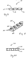
- Non-interlocking solids having preferred motion-limiting portions are illustrated in Figures 1-7 . From a side view, the solids have particular profiles. In the preferred embodiment, the solids have a profile that is substantially similar in shape to a capital letter "T.” Examples of other profiles for solids with motion-limiting portions include, but are not limited to, those illustrated in Figures 9-14 .
- the solids have means for maintaining linear alignment of the support member.
- the means include, but are not limited to, non-interlocking projections and concavities in mateable relationship ( Figures 5-7 , 15 , and 17 ).
- the flexible material and the non-interlocking, motion-limiting, solids are formed as a single construct ( Figure 2C ).
- metals, alloys, and composite materials can be used to make the construct, moldable polymeric materials are particularly suited for forming the flexible material and the non-interlocking, motion-limiting, solids as a single construct.
- the present invention is in the form of a support element having a range of motion in one direction and essentially no range of motion in an opposite direction
- the support member comprises a flexible member combined with a plurality of non-interlocking solids in a single construct, wherein adjacent non-interlocking solids have portions that contact one another and restrict bending of said flexible member in one direction of movement, and wherein said portions of said non-interlocking solids separate from one another when said flexible member is activated in an opposite direction of movement, thereby permitting said flexible member to bend and assume a curved configuration.
- motion-limiting filaments (26) are used in place of, or in addition to, the above-discussed motion-limiting portions.
- a plurality of solids (24) is attached to a flexible material (22) with spaces between adjacent solids.
- the preferred method of attaching the solids to the flexible materials is with heat injection over-molding, also commonly referred to as insert molding.
- the flexible material has a series of holes through the thickness of the material and running along the length of the material. The solids are molded on the flexible material in such a way that bottom portions of the solids fill the holes and wrap around all or part of the flexible material. The resulting construct has solids firmly attached to the flexible material.
- At least one high tensile strength (e.g. , 400 psi, (28.12278 Kg/cm 2 )) and low stretch (e.g. , less than about 3.6 percent elongation at breakage) filament is attached to the solids as a means of limiting the range of motion of the flexible material when the invention is operated in one direction of movement.
- the at least one filament does not restrict motion of the flexible material when the invention is operated in an opposite direction of movement.
- the filament is attached to the solids when the flexible material is in a straightened, or flattened, configuration. When viewed from one side, the filament (26) and flexible material (22) appear substantially in parallel ( Figure 8A ).
- the filament material is made of metallic or polymeric materials.
- Preferred metallic materials include, but are not limited to, stainless steel and alloys there of, or nickel and titanium alloys.
- Preferred polymeric materials include, but are not limited to, aramid fibers available from E. I. du Pont de Nemours and Company, Wilmington, DE, under the tradename KEVLAR® brand fiber, poly(p-phenylenebenzobisoxazole) fiber available from Toyobo Co. Ltd., Osaka, Japan, under the tradename ZYLON® fiber, and an aramid fiber available from Teijin, Osaka, Japan under the tradename TECHNORATM aramid fiber, liquid crystal polymers, polyester, nylon, and heat stabilized (HS) polyethylene.
- aramid fibers available from E. I. du Pont de Nemours and Company, Wilmington, DE, under the tradename KEVLAR® brand fiber, poly(p-phenylenebenzobisoxazole) fiber available from Toyobo Co. Ltd., O
- the filament material can be coated with lubricant or impregnated with resin to increase strength and reduce abrasion. Furthermore, the filament material can be in the form of a straight, twisted or woven yam, woven fabric, fiber, fine wire, or composite reinforced thin film.
- the at least one filament is attached to the solids by gluing, molding, or heat staking.
- the preferred method is insert molding also commonly referred to as over-molding.
- the flexible material is in the form of at least one filament or fiber.
- several filaments or fibers are used together in a substantially parallel array ( Figures 15 and 16 , part 52).
- a base layer of polymeric material (54) encloses and maintains the individual filaments of the array in parallel relationship.
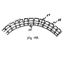
- a first series of non-interlocking, motion-limiting, solids (55) are formed together as a first strip of material (56) and attached to one side of the base layer. The solids are separated from one another by a slit (57), or similarly narrow cutout, formed between adjacent solids.
- the slit extends from an external surface of the first strip through the body of the strip to a location near the bottom of the first strip.
- a second series of non-interlocking solids (58) are optionally formed on the opposite side of the base layer, preferably as a second strip of material (59).
- the additional non-interlocking solids can serve to mechanically balance the non-interlocking, motion-limiting, solids.
- the additional non-interlocking solids can also limit the motion and bend radius of the support member, but to a lesser degree than the first series of non-interlocking solids.
- the second series of non-interlocking solids are separated from one another by a notch, wedge, or similar cutout, formed between adjacent solids.
- the slits, wedges, or notches are preferably provided with a cutout (53) at one end.
- the cutouts prevent the slits, wedges, or notches from extending in length as the support member (50) is repeatedly flexed.
- the cutouts also provide additional flexibility to the support member.
- the present invention is in the form of a support member having a range of motion in one direction and essentially no range of motion in an opposite direction, wherein said support member comprises a length of a first flexible polymeric material comprising a plurality of non-interlocking solids, wherein adjacent non-interlocking solids have portions that contact one another and restrict bending of said flexible member in one direction of movement, and wherein said portions of said non-interlocking solids separate from one another when said flexible member is activated in an opposite direction of movement, thereby permitting said flexible member to bend and assume a curved configuration, and at least one layer of material having at least one reinforcing element embedded therein attached to one side of said first flexible material.
- the invention further comprises a length of a second flexible material comprising a plurality of non-interlocking solids attached to an opposite side of said at least one layer of material.
- a series of non-interlocking, motion-limiting, solids are constructed together as a single continuous strip of material ( Figure 17 , part 68, or Figure 19 , part 78) with a length of flexible material attached to the strip.
- the length of flexible material can be in the form of a strip ( Figure 19 , part 72) or in the form of one or more filaments ( Figure 17 , part 62).
- Narrow slits 64 or 74
- Cutouts (66 or 76) are also provided at one end of each slit to prevent extension of the slits during repeated flexing and to increase the overall flexibility of the support member (60 or 70).
- the present invention is in the form of a support member having a range of motion In one direction and essentially no range of motion in an opposite direction wherein the support member comprises a continuous strip of material comprising a series of non-interlocking, motion-limiting, solids, wherein adjacent non-interlocking solids have portions that contact one another and restrict bending of said flexible member in one direction of movement, and wherein said portions of said non-interlodcing solids separate from one another when said flexible member is activated in an opposite direction of movement, thereby permitting said continuous strip to bend and assume a curved configuration, and at least one reinforcing element embedded in said continuous strip.
- An assembly of conduits, conductors, channels and/or other electro-mechanical elements employing one or more of the above-discussed support members can be constructed in a variety of ways.
- Conductors are substances or media that permit electricity, light, heat, or other forms of energy to pass through them.
- Conduits are pathways for conveying energy, fluids, or gases.
- Channels are hollow tubes or ducts for transferring gases or liquids.
- channels can house support members, conductors, and/or conduits.
- an assembly is constructed with at least one conductor or conduit disposed substantially in parallel with at least one support member and enclosed, or surrounded, in a polymeric jacket or envelope.
- the preferred method of forming the jacket or envelope is by laminating two sheets of a thermoplastic material together with an appropriate adhesive.
- Preferred jacket materials include, but are not limited to fluoropolymers, such as polytetrafluoroethylene, porous polytetrafluoroethylene, perfluoroaxoxy (PFA), fluorinated ethylene polymer (FEP), ethylene-tetrafluoroethylene copolymer (ETFE) available from from E. I.
- thermoplastics such as polyethylene, polypropylene, polystyrene, acrylonitrile butadiene styrene (ABS), polyetheretherketone (PEEK), thermoplastic polyamide, such as NYLON®, polyurethane, polyvinylchloride (PVC), fluorothermoplastics such as DYNEONTM THVTM fluorothermoplastic available from Dyneon, Oakdale, MN., thermoplastic elastomers such as HYTREL® polyester thermoplastic elastomer available from E. I. du Pont de Nemours and Company, Wilmington, DE, and thermoplastic rubbers such as SANTOPRENE® thermoplastic rubbers available from Advanced Elastomer Systems, Akron, OH, and composites there of.
- PVDF polyvinydene fluoride
- thermoplastics such as polyethylene, polypropylene, polystyrene, acrylonitrile butadiene styrene (ABS), polyetheretherketone
- At least one channel is formed by the jacket component (81) during the lamination process.
- the channel is made by enclosing, or surrounding, at least one removable form in a suitable jacket material. Once the jacket is made, the form is removed to leave a channel in its place (82).
- a variety of devices can be placed inside the channel.
- multiple channels are formed and a support member (83), conductor, conduit, and/or other means of transmitting gas, fluid, or energy (84) are placed inside each channel.
- This example describes the construction of a support member of the present invention as illustrated in Figures 1-2 .
- a length of flexible material in the form of 301 High Yield Stainless Steel, 0.25 inches wide and 0.005 inches thick was obtained from Belt Technologies, Inc., Agawam, MA.
- a series of holes 0.093 inches in diameter were stamped in the stainless steel. The holes were spaced 0.385 inches apart.
- the stainless steel was then placed in an insert mold in preparation for attaching of a plurality of non-interlocking, motion-limiting, solids to the stainless steel.
- the insert mold was provided with a form for the solids having an overall shape and profile as illustrated in Figures 1 and 2 , respectively.
- An over-molding technique was used to simultaneously form and attach the solids to the stainless steel.
- the stainless steel was maintained in a curved configuration in the mold to provide space between each individual solid as the solids were formed and attached to the stainless steel.
- a liquid crystal polymer available from Polyplastics Co., Ltd., Osaka, Japan, under the tradename VECTRA® liquid crystal polymer was used to form the non-interlocking, motion-limiting, solids.
- Individual solids were formed over the perforated portions of the flexible stainless steel material in a sequential manner by an over-molding technique.
- a perforation in the stainless steel was aligned with a mold defining a solid and liquid crystal polymer introduced into the mold.
- the solids each had a length of 0.385 inches, a width of 0.28 inches, and a height of 0.165 inches.
- the liquid crystal polymer flowed into the mold and around the flexible stainless steel material to form an individual solid.
- This example describes the construction of a support member of the present invention as illustrated in Figures 3-4 .
- Example1 The materials and methods of this example are the same as those described in Example1 except for the overall shape and profile of the non-interlocking, motion-limiting, solids.
- the overall shape and profile of the solids formed in this example are illustrated in Figures 3 and 4 , respectively.
- the materials and methods of this example are the same as those described in Example1 except for the shape and profile of the non-interlocking, motion-limiting, solids.
- the overall shape of the solids formed in this example is illustrated in Figures 5-6 .
- the profile of the solids is illustrated in Figure 7 .
- the solids of this example have non-interlocking projections and concavities in mateable relationship. These features serve as means for maintaining, linear alignment of the support member.
- This example describes the construction of a support member of the present invention as illustrated in Figure 8 and 8A .
- This embodiment has three main components, a length of flexible material, a plurality of non-interlocking solids, and a series of filaments attached to the solids that restrict motion of the flexible material in one direction, but not in an opposite direction.
- a length of flexible material in the form of 301 High Yield Stainless Steel, 0.25 inches wide and 0.005 inches thick was obtained from Belt Technologies, Inc., Agawam, MA.
- a series of holes 0.093 inches in diameter were stamped in the stainless steel. The holes were spaced 0.32 inches apart. The stainless steel was then placed in an insert mold in preparation for attaching of a plurality of non-interlocklng solids to the stainless steel and a series of filaments to the solids.
- aramid filaments available from E. I. du Pont de Nemours and Company, Wilmington, DE, under the tradename KEVLAR® brand fiber, were suspended 0.13 inches above the stainless steel. The filaments were aligned substantially in parallel with the axis of the stainless steel. Neighboring filaments were spaced approximately 0.05 inches apart. The filaments were held under 5.0 pounds of tension throughout the construction process.
- the insert mold was provided with a form for the non-interlocking solids having an overall shape and profile as illustrated in Figures 8 and 8A , respectively.
- An over-molding technique was used to simultaneously form and attach individual solids to the stainless steel.
- the filaments were also attached to the solids in the over-molding process.
- a liquid crystal polymer available from Polyplastics Co., Ltd., Osaka, Japan, under the tradename VECTRA® liquid crystal polymer was used to form the non-interlocking solids.
- a perforation in the stainless steel was aligned with a mold defining a solid and liquid crystal polymer introduced into the mold.
- the liquid crystal polymer flowed into the mold and around the flexible stainless steel material to form an individual solid.
- the solid became attached to the stainless steel.
- the liquid crystal polymer also flowed around the filaments.
- the filaments became attached to the solids.
- the stainless steel material was advanced through the insert mold to the next perforation and the over-molding process repeated to form another solid and filament array in the series.
- a completed support member of the present invention was removed from the insert mold.
- This example illustrates the construction of a support member of the present invention as illustrated in Figures 15 and 16 .
- This embodiment has three main components.
- the first component is a length of a first flexible polymeric material comprising a plurality of non-interlocking, motion-limiting, solids.
- the second component comprises at least one layer of a second flexible polymeric material having at least one reinforcing element embedded in the material that is attached to the first flexible polymeric material.
- the third component is another layer of a third flexible polymeric material comprising a plurality of non-interlocking, motion-limiting, solids attached to the second component.
- the first and third layers of flexible polymeric material are made from a high modulus polyamid extrusion material available from Creanova, Inc., Frankfurt, Germany under the tradename VESTAMID® high performance polymer as part number L-cf15sw. This material is hard enough to resist compression and cold flow extrusion. The material also has good impact resistance.
- the second, or middle, layer ( Figure 15 , part 54) is made from material that is softer than the material used for layers one and three.
- the material of the second layer also has a lower modulus than the material of the first and third layers.
- This material is also available from Creanova, Inc., Frankfurt, Germany under the trade under the tradename VESTAMID® high performance polymer as part number L2121.
- the second layer is reinforced with a high tensile strength fiber embedded in the polymeric material.
- the fiber is centrally located in the material and runs longitudinally along the length of the material.
- the preferred fiber is an aramid fiber available from E. I. du Pont de Nemours and Company, Wilmington, DE under the tradename KEVLAR® brand fiber, catalog reference Kevlar 49, 1500 denier.
- the fiber has 1.1 twists per inch.
- the fiber is encapsulated in the polymeric material by extruding the material over and around the fiber.
- the three layered support member is formed by simultaneously extruding all three component layers together in a single process.
- the support member is extruded in a curved configuration to allow for notches and slits to be formed in the first and third layers, respectively ( Figure 15B ).
- Transverse notches ( Figure 15 , part 51), or wedges, are cut into the material of layer three with a knife or wedge-shaped tool, while the material is still soft from the extrusion process.
- the notches penetrate through the material of layer three and stop at the material of layer two.
- Transverse slits ( Figure 15 , part 57) are cut into the material of layer one with a knife, or other suitable tool, while the material is still soft from the extrusion process. No gaps are seen between the individual non-interlocking, motion-limiting, solids when the support member is in a straightened configuration.
- stress-relieving holes ( Figure 15 , part 57) are drilled or cut into the sides of the support member at the ends of each notch and slit to prevent propagation of stress-cracks into the second layer material.
- This example illustrates the construction of a support member of the present invention as illustrated in Figures 15A and 16A .
- the first component is a length of a first flexible polymeric material comprising a plurality of non-interlocking, motion-limiting, solids.
- the second component comprises at least one layer of a second flexible polymeric material having at least one reinforcing element embedded in the material attached to the first flexible polymeric material.
- the third component is another layer of a third flexible polymeric material comprising a plurality of non-interlocking, motion-limiting, solids attached to the second component.
- the first and third layers of this embodiment are the same as those described in Example 5, above.
- the second layer is similar to the second layer of Example 5 except the reinforcing element is a metallic strip ( Figure 15A , part 52a).
- the material for the metallic strip is in the form of 301 High Yield Stainless Steel, 0.25 inches wide and 0.005 inches thick and is obtained from Belt Technologies, Inc., Agawam, MA. A series of holes 0.093 inches in diameter are stamped in the stainless steel. The holes are spaced 0.385 inches apart.
- Example 5 The processes of forming the different layers are the same as Example 5.
- the result is a support member of the present invention having a range of motion in one direction and essentially no range of motion in an opposite direction.
- This example illustrates the construction of a support member of the present invention as illustrated in Figures 17 and 18 .
- the first component is a length of a first flexible polymeric material comprising a plurality of non-interlocking, motion-limiting, solids.
- the second component comprises at least one layer of a second flexible polymeric material having at least one reinforcing element embedded in the material attached to the first flexible polymeric material.
- the first layer of flexible polymeric material ( Figure 17 , part 68) is made from a high modulus polyamid extrusion material available from Creanova, Inc., Frankfurt, Germany under the tradename VESTAMID® high performance polymer as part number L-cf15sw. This material is hard enough to resist compression and cold flow extrusion. The material also has good impact resistance.
- the second layer ( Figure 17 , part 63) is made from material that is softer than the material used for the first layer.
- the material of the second layer also has a lower modulus than the material of the first layer. This material is also available from Creanova, Inc., Frankfurt, Germany under the trade under the tradename VESTAMID® high performance polymer as part number L2121.
- the second layer is reinforced with a high tensile strength fiber embedded in the polymeric material ( Figure 17 , part 62).
- the fiber is centrally located in the material and runs longitudinally along the length of the material.
- the preferred fiber is a aramid fiber available from E. I. du Pont de Nemours and Company, Wilmington, DE under the tradename KEVLAR® brand fiber, catalog reference Kevlar 49, 1500 denier.
- the fiber has 1.1 twists per inch.
- the fiber is encapsulated in the polymeric material by extruding the material over and around the fiber.
- the two layered support member is formed by simultaneously extruding both component layers together in a single process.
- the support member is extruded in a curved configuration to allow for notches and slits to be formed in the first layer ( Figure 17A ).
- Transverse slits ( Figure 17 , part 64) are cut into the material of layer one with a knife, or other suitable tool, while the material is still soft from the extrusion process. No gaps are seen between the individual non-interlocking, motion-limiting, solids when the support member is in a straightened configuration.
- stress-relieving holes ( Figure 17 , part 66) are drilled or cut into the sides of the support member at the end of each slit to prevent propagation of stress-cracks into the second layer material.
- This example illustrates the construction of a support member of the present invention as illustrated in Figures 19 and 20 .
- the first component is a length of a first flexible polymeric material comprising a plurality of non-interlocking, motion-limiting, solids.
- the second component comprises at least one layer of as second flexible polymeric material having at least one reinforcing element embedded in the material attached to the first flexible polymeric material.
- the first layer of flexible polymeric material ( Figure 19 , part 78) is made from a high modulus polyamid extrusion material available from Creanova, Inc., Frankfurt, Germany under the tradename VESTAMID® high performance polymer as part number L-cf15sw. This material is hard enough to resist compression and cold flow extrusion. The material also has good impact resistance.
- the second layer ( Figure 19 , part 73) is made from material that is softer than the material used for the first layer.
- the material of the second layer also has a lower modulus than the material of the first layer. This material is also available from Creanova, Inc., Frankfurt, Germany under the trade under the tradename VESTAMID® high performance polymer as part number L2121.
- the second layer is similar to the second layer of Example 7 except the reinforcing element is a metallic strip ( Figure 19 , part 72).
- the material for the metallic strip is in the form of 301 High Yield Stainless Steel, 0.25 inches wide and 0.005 inches thick and is obtained from Belt Technologies, Inc., Agawam, MA A series of holes 0.093 inches in diameter are stamped in the stainless steel. The holes are spaced 0.385 inches apart.
- Example 7 The processes of forming the different layers are the same as Example 7.
- the result Is a support member of the present invention having a range of motion in one direction and essentially no range of motion in an opposite direction.
- the two layered support member is formed by simultaneously extruding both component layers together in a single process.
- the support member is extruded in a curved configuration to allow for notches and slits to be formed in the first and third layers, respectively.
- Transverse slits ( Figure 19 , part 74) are cut into the material of layer one with a knife, or other suitable tool, while the material is still soft from the extrusion process. No gaps are seen between the individual non-interlocking, motion-limiting, solids when the support member is in a straightened configuration.
- stress-relieving holes ( Figure 19 , part 76) are drilled or cut into the sides of the support member at the end of each slit to prevent propagation of stress-cracks into the second layer material.
Landscapes
- Engineering & Computer Science (AREA)
- General Engineering & Computer Science (AREA)
- Architecture (AREA)
- Civil Engineering (AREA)
- Structural Engineering (AREA)
- Mechanical Engineering (AREA)
- Laminated Bodies (AREA)
- Supports For Pipes And Cables (AREA)
- Physical Or Chemical Processes And Apparatus (AREA)
Applications Claiming Priority (3)
| Application Number | Priority Date | Filing Date | Title |
|---|---|---|---|
| US30338202A | 2002-11-22 | 2002-11-22 | |
| US10/695,222 US6858797B2 (en) | 2002-11-22 | 2003-10-28 | Support member for an assembly |
| EP03812032A EP1579543A4 (fr) | 2002-11-22 | 2003-11-20 | Element servant a supporter un ensemble |
Related Parent Applications (1)
| Application Number | Title | Priority Date | Filing Date |
|---|---|---|---|
| EP03812032.5 Division | 2003-11-20 |
Publications (2)
| Publication Number | Publication Date |
|---|---|
| EP2390976A2 true EP2390976A2 (fr) | 2011-11-30 |
| EP2390976A3 EP2390976A3 (fr) | 2012-05-23 |
Family
ID=32505803
Family Applications (1)
| Application Number | Title | Priority Date | Filing Date |
|---|---|---|---|
| EP11004974A Ceased EP2390976A3 (fr) | 2002-11-22 | 2003-11-20 | Élément de support pour assemblage des câbles, conduits ou tuyaux |
Country Status (2)
| Country | Link |
|---|---|
| US (1) | US6858797B2 (fr) |
| EP (1) | EP2390976A3 (fr) |
Cited By (2)
| Publication number | Priority date | Publication date | Assignee | Title |
|---|---|---|---|---|
| CN107850185A (zh) * | 2015-07-29 | 2018-03-27 | 株式会社椿本链条 | 链条用限制弯曲附件 |
| JPWO2019142929A1 (ja) * | 2018-01-19 | 2021-01-28 | 株式会社潤工社 | 支持部材、導管支持装置、および、それを備えた処理装置 |
Families Citing this family (46)
| Publication number | Priority date | Publication date | Assignee | Title |
|---|---|---|---|---|
| JP3716985B2 (ja) * | 2002-11-05 | 2005-11-16 | 株式会社椿本チエイン | ケーブル類支持案内装置 |
| JP3716989B2 (ja) * | 2003-05-07 | 2005-11-16 | 株式会社椿本チエイン | ケーブル類保護案内装置 |
| US7498511B1 (en) * | 2005-11-22 | 2009-03-03 | Securus, Inc. | Pipe hanger |
| DE102006060252B4 (de) * | 2006-01-19 | 2024-09-05 | Tsubakimoto Chain Co. | Schutz- und Führungsvorrichtung für ein Kabel oder einen Schlauch |
| JP4789632B2 (ja) * | 2006-01-20 | 2011-10-12 | 株式会社椿本チエイン | ケーブル類保護案内装置 |
| NL2003509A (en) * | 2008-10-21 | 2010-04-22 | Asml Netherlands Bv | Guiding device and guiding assembly for guiding cables and/or hoses, and a lithographic apparatus. |
| JP4658221B1 (ja) * | 2009-11-26 | 2011-03-23 | 株式会社椿本チエイン | 多関節型ケーブル類保護案内装置 |
| WO2011092991A1 (fr) * | 2010-01-29 | 2011-08-04 | 宇部日東化成株式会社 | Guide-câble |
| JP4749494B1 (ja) * | 2010-04-02 | 2011-08-17 | 株式会社椿本チエイン | ケーブル類保護案内用多関節支持部材 |
| KR101249286B1 (ko) * | 2010-12-02 | 2013-04-01 | 신무현 | 전송라인용 슬리브의 조립형 지지모듈 |
| KR101192299B1 (ko) | 2010-12-02 | 2012-10-17 | 신무현 | 전송라인용 슬리브의 일체형 지지모듈 |
| JP5414704B2 (ja) * | 2011-01-21 | 2014-02-12 | 株式会社椿本チエイン | 多関節型ケーブル類保護案内装置 |
| JP5127943B2 (ja) * | 2011-02-10 | 2013-01-23 | サムウォン アクト インコーポレイテッド | 多関節型ケーブル類保護案内装置 |
| JP5079894B2 (ja) * | 2011-02-15 | 2012-11-21 | 株式会社椿本チエイン | 多関節型ケーブル類保護案内装置 |
| EP2693583B1 (fr) | 2011-03-28 | 2016-02-24 | Junkosha Inc. | Élément de support de câble et dispositif de support de câble |
| WO2012173393A2 (fr) * | 2011-06-16 | 2012-12-20 | Shin Mu Hyun | Module de support de manchon pour ligne de transmission |
| KR101100676B1 (ko) | 2011-06-16 | 2012-01-03 | 신무현 | 전송라인용 슬리브의 지지모듈 |
| KR101216117B1 (ko) | 2011-12-05 | 2012-12-27 | 신무현 | 전송라인용 슬리브의 지지모듈 |
| KR20140137010A (ko) * | 2012-03-22 | 2014-12-01 | 내쇼날 오일웰 파르코 노르웨이 에이에스 | 케이블용 지지 장치 및 이를 이용한 케이블 지지 방법 |
| JP6002656B2 (ja) * | 2013-12-04 | 2016-10-05 | 株式会社椿本チエイン | フラット状伝送装置及びその使用方法 |
| AT516130B1 (de) * | 2014-07-15 | 2016-10-15 | Siemens Ag Oesterreich | Kabelkanal für ein Schienenfahrzeug |
| JP2016131423A (ja) * | 2015-01-13 | 2016-07-21 | 株式会社オートネットワーク技術研究所 | 電線保護部材、電線保護部材付ワイヤーハーネス及びスライド配線装置 |
| JP6317291B2 (ja) * | 2015-04-27 | 2018-04-25 | 株式会社椿本チエイン | ケーブル類保護案内装置及び固定部材 |
| KR101585900B1 (ko) * | 2015-06-02 | 2016-01-15 | 성문규 | 플랫케이블 및 그 제조방법 |
| KR101640021B1 (ko) * | 2016-02-23 | 2016-07-15 | 주식회사 토마스엔지니어링 | 다목적 공간부를 갖는 케이블 |
| US9666976B1 (en) * | 2016-06-02 | 2017-05-30 | Cheng Uei Precision Industry Co., Ltd. | Portable cable assembly |
| KR101772922B1 (ko) * | 2016-06-24 | 2017-08-30 | 박선화 | 케이블 지지 가이드 |
| JP6498653B2 (ja) | 2016-11-08 | 2019-04-10 | 矢崎総業株式会社 | 保護チューブ組立体及び給電装置 |
| EP3352314B1 (fr) | 2017-01-23 | 2020-05-27 | Thomas Engineering Co., Ltd. | Câbles et câbles empilés comprenant un élément de support multi-articulations |
| JP6743744B2 (ja) * | 2017-03-30 | 2020-08-19 | 株式会社オートネットワーク技術研究所 | 外装体及びワイヤーハーネス |
| USD829535S1 (en) * | 2017-07-06 | 2018-10-02 | 308, Llc | Junction box |
| US9949393B1 (en) * | 2017-08-31 | 2018-04-17 | Nzxt Inc. | Cable managing device for case |
| USD826032S1 (en) * | 2017-08-31 | 2018-08-21 | Nzxt Inc. | Cable managing device for case |
| USD826033S1 (en) * | 2017-08-31 | 2018-08-21 | Nzxt Inc. | Cable managing devise for case |
| USD826034S1 (en) * | 2017-08-31 | 2018-08-21 | Nzxt Inc. | Cable managing devise for case |
| USD826700S1 (en) * | 2017-08-31 | 2018-08-28 | Nzxt Inc. | Cable managing device for case |
| USD822459S1 (en) * | 2017-09-05 | 2018-07-10 | Yanegijutsukenkyujo Co., Ltd. | Wiring-piping material fixture for fixing wires or pipes of a rooftop article |
| WO2019151994A1 (fr) | 2018-01-30 | 2019-08-08 | W. L. Gore & Associates, Inc. | Élément de support pour ensemble |
| JP6640255B2 (ja) | 2018-02-20 | 2020-02-05 | 矢崎総業株式会社 | 湾曲規制部材及び給電装置 |
| AU201812789S (en) * | 2018-05-11 | 2018-06-13 | Acteuro Ltd | Chain connector |
| JP6804490B2 (ja) * | 2018-06-27 | 2020-12-23 | 矢崎総業株式会社 | ワイヤハーネス、該ワイヤハーネスを備えた給電装置 |
| US11655916B2 (en) | 2018-12-28 | 2023-05-23 | Junkosha Inc. | Conduit support device |
| KR102272965B1 (ko) * | 2019-01-16 | 2021-07-05 | 윤종철 | 케이블 지지 모듈 및 이를 포함하는 케이블 유닛 |
| US20220085584A1 (en) * | 2019-01-17 | 2022-03-17 | W. L. Gore & Associates Gmbh | Support member assembly |
| IT202000018844A1 (it) * | 2020-07-31 | 2022-01-31 | Soilmec Spa | Apparato di supporto e guida per linee di alimentazione per dispositivi di scavo. |
| US12183483B2 (en) | 2021-12-10 | 2024-12-31 | W.L. Gore & Associates Gmbh | Cable unit |
Citations (1)
| Publication number | Priority date | Publication date | Assignee | Title |
|---|---|---|---|---|
| EP0528141A1 (fr) | 1991-08-17 | 1993-02-24 | ELOCAB SONDERKABEL GmbH & CO KG | Câble d'alimentation non soutenu |
Family Cites Families (57)
| Publication number | Priority date | Publication date | Assignee | Title |
|---|---|---|---|---|
| GB951478A (en) * | 1961-09-21 | 1964-03-04 | Greengate And Irwell Rubber Co | Improvements in means for the supply of electric current or fluid to overhead travelling cranes |
| FR2052270A5 (fr) * | 1969-06-26 | 1971-04-09 | Kabelschlepp Gmbh | |
| US3779003A (en) * | 1972-09-07 | 1973-12-18 | Measurex Corp | Cable carrier with removable plastic links |
| US4023043A (en) * | 1974-08-16 | 1977-05-10 | Megatherm Corporation | Computerized peak-shaving system for alleviating electric utility peak loads |
| CA1011834A (en) * | 1975-04-18 | 1977-06-07 | Canada Wire And Cable Limited | Self-supporting cable |
| CA994553A (en) * | 1975-05-16 | 1976-08-10 | Canada Square Management Ltd. | Temperature control system |
| JPS5562438A (en) * | 1978-11-02 | 1980-05-10 | Olympus Optical Co Ltd | Reversal image pickup apparatus |
| SE425123B (sv) * | 1979-08-21 | 1982-08-30 | Bjorn Gosta Erik Karlsson | Anleggning for central och automatisk avlesning och registrering av abonnenters energiforbrukning |
| SE429378B (sv) * | 1980-06-06 | 1983-08-29 | Bjorn G Karlsson | Mikrodatorbaserad elmetare |
| US4465970A (en) * | 1981-02-26 | 1984-08-14 | General Electric Company | Method and apparatus for multiple rate metering of electrical energy |
| US4933633A (en) * | 1981-06-09 | 1990-06-12 | Adec, Inc. | Computer controlled energy monitoring system |
| US4392344A (en) * | 1981-06-30 | 1983-07-12 | Central Safety Equipment Company | Chain-link cable carrier |
| US4412092A (en) * | 1981-08-24 | 1983-10-25 | W. L. Gore & Associates, Inc. | Multiconductor coaxial cable assembly and method of fabrication |
| JPS5842444U (ja) * | 1981-09-17 | 1983-03-22 | 三ツ星ベルト株式会社 | 動力伝動用vベルト |
| DE3318365A1 (de) * | 1983-05-20 | 1984-11-22 | Kabelschlepp Gmbh, 5900 Siegen | Energiefuehrungskette |
| DE3333543C3 (de) * | 1983-09-16 | 1995-02-09 | Ernst Klein | Selbsttragender Energieleitungsträger |
| US4701154A (en) * | 1985-04-18 | 1987-10-20 | National Standard Company | Reinforced belt assembly and method of manufacture |
| US4847781A (en) * | 1986-09-23 | 1989-07-11 | Associated Data Consoltants | Energy management system |
| GB2219439A (en) * | 1988-06-06 | 1989-12-06 | Gore & Ass | Flexible housing |
| JPH03216329A (ja) * | 1990-01-22 | 1991-09-24 | Nippon Steel Chem Co Ltd | 繊維強化複合ベルト |
| IE75901B1 (en) * | 1990-05-16 | 1997-10-08 | Becton Dickinson Co | Multiconductor and support and machine and method for making |
| JPH04131600A (ja) * | 1990-09-19 | 1992-05-06 | Hitachi Ltd | 都市エネルギーシステム |
| ES2075302T3 (es) * | 1991-10-31 | 1995-10-01 | Gore W L & Ass Gmbh | Disposicion de guiado para conduccion. |
| ES2145334T3 (es) * | 1991-11-26 | 2000-07-01 | Kabelschlepp Gmbh | Disposicion de guiado de tubo con fondos de ranura ensanchados. |
| US5481140A (en) * | 1992-03-10 | 1996-01-02 | Mitsubishi Denki Kabushiki Kaisha | Demand control apparatus and power distribution control system |
| US5831550A (en) * | 1992-06-01 | 1998-11-03 | Centro De Pesquisas De Energia Eletrica - Cepel | System and process for the measurement of the electric energy consumption of a plurality of consumers |
| US5576700A (en) * | 1992-08-26 | 1996-11-19 | Scientific-Atlanta | Apparatus and method for controlling an electrical load and monitoring control operations and the electrical load |
| IT1257167B (it) * | 1992-10-27 | 1996-01-05 | Metodo per il miglioramento della gestione delle reti di distribuzionein particolare di gas, acqua, energia elettrica, calore. | |
| CA2116168A1 (fr) * | 1993-03-02 | 1994-09-03 | Gregory Cmar | Procede d'identification des modeles de consommation et de demande d'energie electrique servant a prevoir et a verifier les effets des changements proposes et mise en oeuvre des changements pour conserver l'energie |
| US5462225A (en) * | 1994-02-04 | 1995-10-31 | Scientific-Atlanta, Inc. | Apparatus and method for controlling distribution of electrical energy to a space conditioning load |
| US5963457A (en) * | 1994-03-18 | 1999-10-05 | Hitachi, Ltd. | Electrical power distribution monitoring system and method |
| US5448670A (en) * | 1994-06-10 | 1995-09-05 | Commscope, Inc. | Elliptical aerial self-supporting fiber optic cable and associated apparatus and methods |
| US5696501A (en) * | 1994-08-02 | 1997-12-09 | General Electric Company | Method and apparatus for performing the register functions for a plurality of metering devices at a common node |
| US5572438A (en) * | 1995-01-05 | 1996-11-05 | Teco Energy Management Services | Engery management and building automation system |
| US5627759A (en) * | 1995-05-31 | 1997-05-06 | Process Systems, Inc. | Electrical energy meters having real-time power quality measurement and reporting capability |
| TW300314B (fr) * | 1995-06-08 | 1997-03-11 | Tokyo Electron Co Ltd | |
| US5864710A (en) * | 1996-07-23 | 1999-01-26 | Compaq Computer Corporation | Controllerless modem |
| US6112159A (en) * | 1996-08-01 | 2000-08-29 | Siemens Power Transmission & Distribution, Llc | Robust electrical utility meter |
| US5974369A (en) * | 1996-08-28 | 1999-10-26 | Wps Energy Services Inc. | Recording and processing metered information |
| EP1018022A4 (fr) * | 1996-10-22 | 2000-12-06 | Abb Power T & D Co | Dispositif de mesure d'energie comportant des systemes de diagnostic et de controle de qualite d'energie |
| DE19647322A1 (de) * | 1996-11-15 | 1998-05-20 | Kabelschlepp Gmbh | Kettenglied aus verschiedenen Werkstoffen und Verfahren zu dessen Herstellung |
| US6029092A (en) * | 1996-11-21 | 2000-02-22 | Intellinet, Inc. | System and method for providing modular control and for managing energy consumption |
| US6047274A (en) * | 1997-02-24 | 2000-04-04 | Geophonic Networks, Inc. | Bidding for energy supply |
| US5897607A (en) * | 1997-02-28 | 1999-04-27 | Jenney Systems Associates, Ltd. | Automatic meter reading system |
| JP3709892B2 (ja) * | 1997-03-13 | 2005-10-26 | カーベルシユレツプ ゲゼルシヤフト ミツト ベシユレンクテル ハフツング | 異なった2つの安定な位置に動かすことができる蓋を有する保護要素 |
| DE19710489A1 (de) * | 1997-03-13 | 1998-09-24 | Kabelschlepp Gmbh | Faltbares Schutzelement für Leitungen |
| US6088659A (en) * | 1997-09-11 | 2000-07-11 | Abb Power T&D Company Inc. | Automated meter reading system |
| US6157874A (en) * | 1997-10-31 | 2000-12-05 | Basic Resources, Inc. | Power control systems and processes |
| US6122603A (en) * | 1998-05-29 | 2000-09-19 | Powerweb, Inc. | Multi-utility energy control system with dashboard |
| US6327541B1 (en) * | 1998-06-30 | 2001-12-04 | Ameren Corporation | Electronic energy management system |
| US6147484A (en) * | 1998-07-08 | 2000-11-14 | Smith; Richard T. | Device for measuring power using switchable impedance |
| US6107565A (en) * | 1998-11-17 | 2000-08-22 | A&A Manufacturing Co., Inc. | Covered energy transmission line carrier |
| CA2349707C (fr) * | 1998-11-19 | 2005-03-29 | The Gates Corporation | Courroie de transmission d'energie |
| US6067482A (en) * | 1999-01-08 | 2000-05-23 | Hussmann Corporation | Load shifting control system for commercial refrigeration |
| US6442318B1 (en) * | 1999-11-23 | 2002-08-27 | Schott Fiber Optics, Inc. | Prefabricated optical fiber ribbon cable for connectorizing with a terminal connector and methods of connectorizing and fabricating the same |
| DE19962829A1 (de) * | 1999-12-23 | 2001-08-23 | Kabelschlepp Gmbh | Strang und Verfahren zur Herstellung eines faserverstärkten Stranges einer Leitungsführungsanordnung |
| US6653568B1 (en) * | 2002-09-13 | 2003-11-25 | Panduit Corp. | Flexible harness wrap |
-
2003
- 2003-10-28 US US10/695,222 patent/US6858797B2/en not_active Expired - Lifetime
- 2003-11-20 EP EP11004974A patent/EP2390976A3/fr not_active Ceased
Patent Citations (1)
| Publication number | Priority date | Publication date | Assignee | Title |
|---|---|---|---|---|
| EP0528141A1 (fr) | 1991-08-17 | 1993-02-24 | ELOCAB SONDERKABEL GmbH & CO KG | Câble d'alimentation non soutenu |
Cited By (4)
| Publication number | Priority date | Publication date | Assignee | Title |
|---|---|---|---|---|
| CN107850185A (zh) * | 2015-07-29 | 2018-03-27 | 株式会社椿本链条 | 链条用限制弯曲附件 |
| CN107850185B (zh) * | 2015-07-29 | 2019-12-27 | 株式会社椿本链条 | 链条用限制弯曲附件 |
| JPWO2019142929A1 (ja) * | 2018-01-19 | 2021-01-28 | 株式会社潤工社 | 支持部材、導管支持装置、および、それを備えた処理装置 |
| JP7240651B2 (ja) | 2018-01-19 | 2023-03-16 | 株式会社潤工社 | 支持部材、導管支持装置、および、それを備えた処理装置 |
Also Published As
| Publication number | Publication date |
|---|---|
| EP2390976A3 (fr) | 2012-05-23 |
| US6858797B2 (en) | 2005-02-22 |
| US20040112625A1 (en) | 2004-06-17 |
Similar Documents
| Publication | Publication Date | Title |
|---|---|---|
| US6858797B2 (en) | Support member for an assembly | |
| JP4157096B2 (ja) | アセンブリ用支持部材 | |
| CN102918731B (zh) | 线缆支承构件及线缆支承装置 | |
| JP4658221B1 (ja) | 多関節型ケーブル類保護案内装置 | |
| EP0664864B1 (fr) | Conduite ondulee multicouche comportant des couches en plastique fluore | |
| US8450667B2 (en) | Flexible, electrically heatable hose | |
| EP0790624B1 (fr) | Assemblage perfectionné de transmission de signaux | |
| KR20140027352A (ko) | 굽힘 감쇠를 줄이기 위해 섬유 이동을 가능케 하는 광 섬유 케이블들 | |
| KR20120085188A (ko) | 다관절형 케이블류 보호 안내 장치 | |
| KR20120038495A (ko) | 절연 복합 전력 케이블, 및 이를 제조 및 사용하는 방법 | |
| US12300950B2 (en) | Internally sprung shunt | |
| WO2010109951A1 (fr) | Matériau à stries pour sections mobiles | |
| CA2994583C (fr) | Bande d'attache de cable renforcee et procede de fabrication | |
| KR100649795B1 (ko) | 열가소성 연결 핀 | |
| JP5032714B1 (ja) | ケーブル支持部材 | |
| JP4842495B2 (ja) | 編組ホース補強材 | |
| HK1164555A (en) | Support member for an assembly of conductors, conduits or pipes | |
| EP1781956B1 (fr) | Faisceaux de cables comprenant une couche de reduction de bruit | |
| KR20210114505A (ko) | 지지 부재 조립체 | |
| WO2019151994A1 (fr) | Élément de support pour ensemble | |
| WO1995009376A1 (fr) | Cable souple | |
| US12183483B2 (en) | Cable unit | |
| NL1041122B1 (en) | Drive belt. | |
| EP1875102A1 (fr) | Courroie de transmission de puissance pour transmission de charges élevées | |
| WO1994006126A1 (fr) | Cable electrique miniature |
Legal Events
| Date | Code | Title | Description |
|---|---|---|---|
| AC | Divisional application: reference to earlier application |
Ref document number: 1579543 Country of ref document: EP Kind code of ref document: P |
|
| AK | Designated contracting states |
Kind code of ref document: A2 Designated state(s): AT BE BG CH CY CZ DE DK EE ES FI FR GB GR HU IE IT LI LU MC NL PT RO SE SI SK TR |
|
| PUAI | Public reference made under article 153(3) epc to a published international application that has entered the european phase |
Free format text: ORIGINAL CODE: 0009012 |
|
| PUAL | Search report despatched |
Free format text: ORIGINAL CODE: 0009013 |
|
| AK | Designated contracting states |
Kind code of ref document: A3 Designated state(s): AT BE BG CH CY CZ DE DK EE ES FI FR GB GR HU IE IT LI LU MC NL PT RO SE SI SK TR |
|
| RIC1 | Information provided on ipc code assigned before grant |
Ipc: H02G 11/00 20060101ALI20120418BHEP Ipc: F16G 13/16 20060101ALI20120418BHEP Ipc: H02G 3/04 20060101AFI20120418BHEP |
|
| REG | Reference to a national code |
Ref country code: HK Ref legal event code: DE Ref document number: 1164555 Country of ref document: HK |
|
| 17P | Request for examination filed |
Effective date: 20121121 |
|
| 17Q | First examination report despatched |
Effective date: 20140527 |
|
| RAP1 | Party data changed (applicant data changed or rights of an application transferred) |
Owner name: W.L. GORE & ASSOCIATES, INC. |
|
| STAA | Information on the status of an ep patent application or granted ep patent |
Free format text: STATUS: THE APPLICATION HAS BEEN REFUSED |
|
| 18R | Application refused |
Effective date: 20181129 |