EP2390995A2 - Appareil de production d'énergie à rendement de production d'énergie et force de rotation améliorés - Google Patents
Appareil de production d'énergie à rendement de production d'énergie et force de rotation améliorés Download PDFInfo
- Publication number
- EP2390995A2 EP2390995A2 EP09838931A EP09838931A EP2390995A2 EP 2390995 A2 EP2390995 A2 EP 2390995A2 EP 09838931 A EP09838931 A EP 09838931A EP 09838931 A EP09838931 A EP 09838931A EP 2390995 A2 EP2390995 A2 EP 2390995A2
- Authority
- EP
- European Patent Office
- Prior art keywords
- plates
- coil
- magnet
- magnets
- coils
- Prior art date
- Legal status (The legal status is an assumption and is not a legal conclusion. Google has not performed a legal analysis and makes no representation as to the accuracy of the status listed.)
- Withdrawn
Links
- 230000006698 induction Effects 0.000 claims abstract description 17
- 230000005611 electricity Effects 0.000 claims description 10
- XLYOFNOQVPJJNP-UHFFFAOYSA-N water Substances O XLYOFNOQVPJJNP-UHFFFAOYSA-N 0.000 abstract description 13
- XEEYBQQBJWHFJM-UHFFFAOYSA-N Iron Chemical group [Fe] XEEYBQQBJWHFJM-UHFFFAOYSA-N 0.000 description 3
- 238000000034 method Methods 0.000 description 2
- 238000012986 modification Methods 0.000 description 2
- 230000004048 modification Effects 0.000 description 2
- 238000000926 separation method Methods 0.000 description 2
- 230000009471 action Effects 0.000 description 1
- 230000004913 activation Effects 0.000 description 1
- 230000008859 change Effects 0.000 description 1
- 238000007796 conventional method Methods 0.000 description 1
- 230000000694 effects Effects 0.000 description 1
- 238000005265 energy consumption Methods 0.000 description 1
- 230000006872 improvement Effects 0.000 description 1
- 238000009434 installation Methods 0.000 description 1
- 239000010865 sewage Substances 0.000 description 1
Images

Classifications
-
- F—MECHANICAL ENGINEERING; LIGHTING; HEATING; WEAPONS; BLASTING
- F03—MACHINES OR ENGINES FOR LIQUIDS; WIND, SPRING, OR WEIGHT MOTORS; PRODUCING MECHANICAL POWER OR A REACTIVE PROPULSIVE THRUST, NOT OTHERWISE PROVIDED FOR
- F03D—WIND MOTORS
- F03D3/00—Wind motors with rotation axis substantially perpendicular to the air flow entering the rotor
-
- H—ELECTRICITY
- H02—GENERATION; CONVERSION OR DISTRIBUTION OF ELECTRIC POWER
- H02K—DYNAMO-ELECTRIC MACHINES
- H02K17/00—Asynchronous induction motors; Asynchronous induction generators
- H02K17/42—Asynchronous induction generators
-
- F—MECHANICAL ENGINEERING; LIGHTING; HEATING; WEAPONS; BLASTING
- F03—MACHINES OR ENGINES FOR LIQUIDS; WIND, SPRING, OR WEIGHT MOTORS; PRODUCING MECHANICAL POWER OR A REACTIVE PROPULSIVE THRUST, NOT OTHERWISE PROVIDED FOR
- F03B—MACHINES OR ENGINES FOR LIQUIDS
- F03B3/00—Machines or engines of reaction type; Parts or details peculiar thereto
-
- H—ELECTRICITY
- H02—GENERATION; CONVERSION OR DISTRIBUTION OF ELECTRIC POWER
- H02K—DYNAMO-ELECTRIC MACHINES
- H02K16/00—Machines with more than one rotor or stator
-
- H—ELECTRICITY
- H02—GENERATION; CONVERSION OR DISTRIBUTION OF ELECTRIC POWER
- H02K—DYNAMO-ELECTRIC MACHINES
- H02K21/00—Synchronous motors having permanent magnets; Synchronous generators having permanent magnets
- H02K21/12—Synchronous motors having permanent magnets; Synchronous generators having permanent magnets with stationary armatures and rotating magnets
- H02K21/24—Synchronous motors having permanent magnets; Synchronous generators having permanent magnets with stationary armatures and rotating magnets with magnets axially facing the armatures, e.g. hub-type cycle dynamos
-
- H—ELECTRICITY
- H02—GENERATION; CONVERSION OR DISTRIBUTION OF ELECTRIC POWER
- H02K—DYNAMO-ELECTRIC MACHINES
- H02K7/00—Arrangements for handling mechanical energy structurally associated with dynamo-electric machines, e.g. structural association with mechanical driving motors or auxiliary dynamo-electric machines
- H02K7/18—Structural association of electric generators with mechanical driving motors, e.g. with turbines
- H02K7/1807—Rotary generators
- H02K7/1823—Rotary generators structurally associated with turbines or similar engines
-
- F—MECHANICAL ENGINEERING; LIGHTING; HEATING; WEAPONS; BLASTING
- F05—INDEXING SCHEMES RELATING TO ENGINES OR PUMPS IN VARIOUS SUBCLASSES OF CLASSES F01-F04
- F05B—INDEXING SCHEME RELATING TO WIND, SPRING, WEIGHT, INERTIA OR LIKE MOTORS, TO MACHINES OR ENGINES FOR LIQUIDS COVERED BY SUBCLASSES F03B, F03D AND F03G
- F05B2210/00—Working fluid
- F05B2210/16—Air or water being indistinctly used as working fluid, i.e. the machine can work equally with air or water without any modification
-
- F—MECHANICAL ENGINEERING; LIGHTING; HEATING; WEAPONS; BLASTING
- F05—INDEXING SCHEMES RELATING TO ENGINES OR PUMPS IN VARIOUS SUBCLASSES OF CLASSES F01-F04
- F05B—INDEXING SCHEME RELATING TO WIND, SPRING, WEIGHT, INERTIA OR LIKE MOTORS, TO MACHINES OR ENGINES FOR LIQUIDS COVERED BY SUBCLASSES F03B, F03D AND F03G
- F05B2240/00—Components
- F05B2240/90—Mounting on supporting structures or systems
- F05B2240/94—Mounting on supporting structures or systems on a movable wheeled structure
- F05B2240/941—Mounting on supporting structures or systems on a movable wheeled structure which is a land vehicle
-
- H—ELECTRICITY
- H02—GENERATION; CONVERSION OR DISTRIBUTION OF ELECTRIC POWER
- H02K—DYNAMO-ELECTRIC MACHINES
- H02K2213/00—Specific aspects, not otherwise provided for and not covered by codes H02K2201/00 - H02K2211/00
- H02K2213/12—Machines characterised by the modularity of some components
-
- Y—GENERAL TAGGING OF NEW TECHNOLOGICAL DEVELOPMENTS; GENERAL TAGGING OF CROSS-SECTIONAL TECHNOLOGIES SPANNING OVER SEVERAL SECTIONS OF THE IPC; TECHNICAL SUBJECTS COVERED BY FORMER USPC CROSS-REFERENCE ART COLLECTIONS [XRACs] AND DIGESTS
- Y02—TECHNOLOGIES OR APPLICATIONS FOR MITIGATION OR ADAPTATION AGAINST CLIMATE CHANGE
- Y02E—REDUCTION OF GREENHOUSE GAS [GHG] EMISSIONS, RELATED TO ENERGY GENERATION, TRANSMISSION OR DISTRIBUTION
- Y02E10/00—Energy generation through renewable energy sources
- Y02E10/20—Hydro energy
-
- Y—GENERAL TAGGING OF NEW TECHNOLOGICAL DEVELOPMENTS; GENERAL TAGGING OF CROSS-SECTIONAL TECHNOLOGIES SPANNING OVER SEVERAL SECTIONS OF THE IPC; TECHNICAL SUBJECTS COVERED BY FORMER USPC CROSS-REFERENCE ART COLLECTIONS [XRACs] AND DIGESTS
- Y02—TECHNOLOGIES OR APPLICATIONS FOR MITIGATION OR ADAPTATION AGAINST CLIMATE CHANGE
- Y02E—REDUCTION OF GREENHOUSE GAS [GHG] EMISSIONS, RELATED TO ENERGY GENERATION, TRANSMISSION OR DISTRIBUTION
- Y02E10/00—Energy generation through renewable energy sources
- Y02E10/70—Wind energy
- Y02E10/74—Wind turbines with rotation axis perpendicular to the wind direction
Definitions
- the present invention relates to a generator that can produce electric power using water power, wave power or wind power, and more specially to a generator with improved generation efficiency and rotational force, in which coil plates where horizontally wound generation coils are radially arranged at predetermined intervals and magnet plates where a plurality of magnets are radially arranged at predetermined intervals are sequentially arrayed on a rotating shaft, and a plurality of induction coils and electromotive coils installed on inner and outer cylinders proximate to the opposed ends of the magnets are separately arranged on the coil plates, so as to obtain improved generation efficiency as coil plates and magnet plates rotate in mutually opposing directions, as well as the rotational force is increased further by increasing the repulsive force between coil plates and magnet plates.
- a generator is an apparatus which converts dynamic energy into electric energy. It gets necessary rotational power from water power, wave power, or a power means such as a steam or diesel engine, and rotates cylindrical magnets using this power. In such a generator, when the magnets rotate, electric charge is induced in the coil wound on the iron core located around the magnet to generate electric current.
- the iron core installed for induction activation generates an attractive force that attracts other rotating magnets in the center. Because of that, it requires an excessive motor power, so consequently energy consumption is very high. Not only that, because attractive force acts as rotational resistance, it leads to unnecessarily large consumption of rotational power for rotating the magnet.
- the conventional cylindrical magnet and iron core cannot but adopt a tetrapolar induction method due to the constraint of installation space. Accordingly, high-speed rotation is needed to produce electricity of necessary capacity and due to that, it has a problem that economic efficiency is considerably low.
- the generator disclosed in the above patent application comprises upper and lower fixed plates of non-magnet arranged in separation up and down, a plurality of magnets radially separately arranged on the fixed plate, and rotating discs arranged between the fixed plates. On the rotating disc are radially arranged horizontally wound coil units.
- the magnet on the lower fixed plate located below the rotating disc induces electric charge to generate electric current, and the magnet on the upper fixed plate located above provides alternatingly attractive force and repulsive force to the coil unit in the direction of rotation.
- the generator as mentioned above is of such a form that only the coil plate is rotated while the magnet plate with the magnets separately arranged is fixed. Therefore, it has a problem in that if wind power or water power is weak, sufficient generation capacity cannot be obtained and the generation efficiency is low.
- a generator comprising magnet plates and coil plates which are provided with a plurality of blades that are protruded inclined in mutually opposing directions on the outer circumference thereof, so that the magnet plates and the coil plates are rotated simultaneously in mutually opposing directions, wherein on the coil plates are formed in protrusion an inner cylinder and outer cylinder at locations separated from both ends of the magnets, and on the outer circumference of the inner cylinder are installed induction coils arranged at predetermined intervals toward the inside end of the magnets, and on the inner circumference of the outer cylinder are installed electromotive coils arranged at predetermined intervals toward the outside end of the magnets, wherein the induction coils and electromotive coils are connected each other by a direct current converting circuit.
- the present invention it is possible to obtain a further increased quantity of generation by means of the magnet plates and coil plates that rotate in mutually opposing directions even in the case that water power or wind power used in generation is weak.
- the energy supply source such as wind power, wave power or water power acts continuously or intermittently
- the rotational force between the magnet plates and coil plates is increased greatly by the electromotive coils that confer repulsive force on the magnets to make it possible to produce much higher generation energy, so it is very economical.
- Fig. 1 is an exploded perspective view showing a magnet plate and coil plate of a generator according to the present invention
- Fig. 2 is a sectional view showing the assembled state of the generator according to the present invention
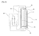
- Fig. 3 is an enlarged sectional view showing major parts of the generator according to the present invention.
- the generator according to the present invention if the magnet plates 10 and 10' and coil plates 20 and 20' that are arranged in separation from each other rotate by external force, electric charge is induced from a plurality of magnets 11 and 11' radially arranged at predetermined intervals on the magnets plates 10 and 10' in the generation coils 21 and 21' radially arranged at predetermined intervals on the coil plates 20 and 20'. Accordingly, electricity is generated from generation coils 21 and 21' of serially-connected shape, so it is possible to obtain desired electric power.
- the magnet plates 10 and 10' and coil plates 20 and 20' are constructed in such a way that they rotate in mutually opposing directions.
- both of the magnet plates 10 and 10' are fixed on a single rotating shaft 40 both ends of which are mounted rotatably on a main body of the generator, and the coil plates 20 and 20' are rotatably mounted on the rotating shaft 40 via bearings 41.
- the blades 12 and 22 may be formed in such a way that they protrude monolithically from the outer circumference of the magnet plates 10 and 10' and coil plates 20 and 20', or may be attached in a state inclined at a predetermined angle by using joining means such as a hinge or bracket. Also, these blades may be formed on the outer circumference or formed transversely in protrusion on the inner circumference.
- the magnet plates 10 and 10' and coil plates 20 and 20' are rotated by external force acting on the blades 12 and 22 which are arranged inclined at a predetermined angle in mutually opposing directions as mentioned above.
- the blades 12 and 22 are arranged inclined in mutually opposing directions, so the magnet plates 10 and 10' and coil plates 20 and 20' are rotated in mutually opposing directions.
- the magnet plates 11 and 11' and induction coils 25 rotating in mutually opposing directions have the quantity of rotation doubled. Therefore, the electricity generation is greatly increased in proportion to the doubled quantity of rotation.
- an inner cylinder 23 and outer cylinder 24 at the locations separated at a predetermined interval in a radius direction from both ends of the magnets 11 and 11'.
- On the outer circumference of the inner cylinder 23 are correspondingly arranged the induction coils 25 toward the inside end of the magnets 11 and 11', and on the inner circumference of the outer cylinder 24 are correspondingly arranged the electromotive coils 26 toward the outside end of the magnets 11 and 11'.
- the induction coils 25 and electromotive coils 26 are mutually connected through a direct current converting circuit 30, the current generated from the induction coils 25 is converted into a form of direct current as it passes through the direct current converting circuit 30 before it is supplied to the electromotive coils 26.
- the generator according to the present invention can be effectively used also in an area where wind is weak or wind blows intermittently, can use water power flowing along a brook, small stream or sewage pipe or water supply pipe, and can be installed on the rooftop of a common house to be used for the purpose of supplying electric power indoors.
Landscapes
- Engineering & Computer Science (AREA)
- Power Engineering (AREA)
- Chemical & Material Sciences (AREA)
- Combustion & Propulsion (AREA)
- Mechanical Engineering (AREA)
- General Engineering & Computer Science (AREA)
- Life Sciences & Earth Sciences (AREA)
- Sustainable Development (AREA)
- Sustainable Energy (AREA)
- Wind Motors (AREA)
- Connection Of Motors, Electrical Generators, Mechanical Devices, And The Like (AREA)
- Permanent Magnet Type Synchronous Machine (AREA)
- Other Liquid Machine Or Engine Such As Wave Power Use (AREA)
Applications Claiming Priority (2)
| Application Number | Priority Date | Filing Date | Title |
|---|---|---|---|
| KR1020090005867A KR100988667B1 (ko) | 2009-01-23 | 2009-01-23 | 발전 효율과 회전력 향상이 이루어진 발전장치 |
| PCT/KR2009/007563 WO2010085044A2 (fr) | 2009-01-23 | 2009-12-17 | Appareil de production d'énergie à rendement de production d'énergie et force de rotation améliorés |
Publications (1)
| Publication Number | Publication Date |
|---|---|
| EP2390995A2 true EP2390995A2 (fr) | 2011-11-30 |
Family
ID=42356290
Family Applications (1)
| Application Number | Title | Priority Date | Filing Date |
|---|---|---|---|
| EP09838931A Withdrawn EP2390995A2 (fr) | 2009-01-23 | 2009-12-17 | Appareil de production d'énergie à rendement de production d'énergie et force de rotation améliorés |
Country Status (6)
| Country | Link |
|---|---|
| US (1) | US8648512B2 (fr) |
| EP (1) | EP2390995A2 (fr) |
| JP (1) | JP5535242B2 (fr) |
| KR (1) | KR100988667B1 (fr) |
| CN (1) | CN102292901B (fr) |
| WO (1) | WO2010085044A2 (fr) |
Cited By (2)
| Publication number | Priority date | Publication date | Assignee | Title |
|---|---|---|---|---|
| WO2023113612A1 (fr) * | 2021-12-16 | 2023-06-22 | World Wide Wind Tech As | Éolienne à rotors contrarotatifs et centrale éolienne comprenant une éolienne à rotors contrarotatifs |
| EP4403768A1 (fr) * | 2023-01-18 | 2024-07-24 | Bielarski Tadeusz | Éolienne avec un générateur d'énergie à deux rotors |
Families Citing this family (15)
| Publication number | Priority date | Publication date | Assignee | Title |
|---|---|---|---|---|
| US9605663B2 (en) * | 2010-08-24 | 2017-03-28 | Qwtip Llc | System and method for separating fluids and creating magnetic fields |
| US10790723B2 (en) | 2010-08-24 | 2020-09-29 | Qwtip Llc | Disk-pack turbine |
| KR101155128B1 (ko) * | 2011-01-06 | 2012-06-11 | 원제영 | 발전을 겸용한 비엘디씨 모터 |
| AU2012298623A1 (en) | 2011-08-24 | 2014-04-10 | Qwtip Llc | Water treatment system and method |
| US9474991B2 (en) | 2011-08-24 | 2016-10-25 | Qwtip, Llc | Water treatment system and method |
| US9469553B2 (en) | 2011-08-24 | 2016-10-18 | Qwtip, Llc | Retrofit attachments for water treatment systems |
| WO2013130901A1 (fr) | 2012-02-28 | 2013-09-06 | Qwtip Llc | Système et procédé de désalinisation et/ou de production de gaz |
| WO2013130888A1 (fr) | 2012-02-29 | 2013-09-06 | Qwtip Llc | Système et procédé de lévitation et de distribution |
| CN102738922A (zh) * | 2012-05-05 | 2012-10-17 | 张学文 | 圆盘高压直流发电机 |
| KR101308317B1 (ko) | 2013-03-19 | 2013-10-04 | 장석호 | 분할 코일체를 갖는 코일판과 분할 자석을 갖는 왕복 이동형 자석판을 이용한 발전겸용 전동장치 |
| KR101369614B1 (ko) * | 2013-12-10 | 2014-03-04 | 장석호 | 복수의 보조동력 구조를 갖는 발전겸용 전동수단을 갖는 바퀴 |
| CN105449961A (zh) * | 2016-01-31 | 2016-03-30 | 李学智 | 一种正逆双转子永磁发电机 |
| CN106812664B (zh) * | 2016-05-06 | 2019-08-20 | 科德数控股份有限公司 | 一种根据风向应变帆的迎风角度的风力直驱发电机 |
| TWI709689B (zh) * | 2017-05-22 | 2020-11-11 | 李受勳 | 交通載具的風力發電設備 |
| CN110380588A (zh) * | 2019-06-27 | 2019-10-25 | 夏玉峰 | 一种高效直流发电机 |
Family Cites Families (14)
| Publication number | Priority date | Publication date | Assignee | Title |
|---|---|---|---|---|
| US4578606A (en) * | 1984-12-13 | 1986-03-25 | Buehler Products, Inc. | Brushless DC electric motor and tachogenerator assembly |
| JPS63277455A (ja) * | 1987-05-07 | 1988-11-15 | Shicoh Eng Co Ltd | ハイブリツドモ−タ |
| JPH07174067A (ja) * | 1992-01-20 | 1995-07-11 | Bitsugusu:Kk | 二重ローター風力発電機 |
| US6426577B1 (en) * | 1998-05-01 | 2002-07-30 | Nisso Electric Corporation | Thrust-controllable rotary synchronous machine |
| JP2002325412A (ja) | 2001-04-25 | 2002-11-08 | Mitsubishi Heavy Ind Ltd | アキシャルギャップ型電動機、発電機および電動発電機 |
| JP2003065204A (ja) | 2001-08-27 | 2003-03-05 | Ebara Corp | 風力発電用発電装置 |
| JP2003129935A (ja) * | 2001-10-26 | 2003-05-08 | Mitsubishi Heavy Ind Ltd | 風力発電装置 |
| JP2003333815A (ja) * | 2002-05-10 | 2003-11-21 | Kurachi Haruyoshi | 低速回転でも発電量の多い多極同期発電機 |
| JP4827380B2 (ja) * | 2003-01-28 | 2011-11-30 | 金原 士朗 | 風力発電システム |
| JP2005030374A (ja) * | 2003-07-10 | 2005-02-03 | Seishi Kanko | 風力発電装置 |
| JP2005160197A (ja) | 2003-11-25 | 2005-06-16 | Meiki Sangyo Kk | 風水力利用発電機 |
| JP4441516B2 (ja) * | 2006-09-27 | 2010-03-31 | 政春 加藤 | 発電装置 |
| CN101217247A (zh) * | 2007-01-05 | 2008-07-09 | 叶建国 | 一种电机(电动机和发电机)装置 |
| JP4361568B2 (ja) | 2007-01-17 | 2009-11-11 | 東京エレクトロン株式会社 | 基板処理装置および基板処理方法 |
-
2009
- 2009-01-23 KR KR1020090005867A patent/KR100988667B1/ko active Active
- 2009-12-17 JP JP2011547761A patent/JP5535242B2/ja not_active Expired - Fee Related
- 2009-12-17 EP EP09838931A patent/EP2390995A2/fr not_active Withdrawn
- 2009-12-17 CN CN200980155282XA patent/CN102292901B/zh not_active Expired - Fee Related
- 2009-12-17 WO PCT/KR2009/007563 patent/WO2010085044A2/fr not_active Ceased
- 2009-12-17 US US13/138,186 patent/US8648512B2/en not_active Expired - Fee Related
Non-Patent Citations (1)
| Title |
|---|
| See references of WO2010085044A2 * |
Cited By (2)
| Publication number | Priority date | Publication date | Assignee | Title |
|---|---|---|---|---|
| WO2023113612A1 (fr) * | 2021-12-16 | 2023-06-22 | World Wide Wind Tech As | Éolienne à rotors contrarotatifs et centrale éolienne comprenant une éolienne à rotors contrarotatifs |
| EP4403768A1 (fr) * | 2023-01-18 | 2024-07-24 | Bielarski Tadeusz | Éolienne avec un générateur d'énergie à deux rotors |
Also Published As
| Publication number | Publication date |
|---|---|
| JP2012516128A (ja) | 2012-07-12 |
| CN102292901B (zh) | 2013-10-09 |
| WO2010085044A3 (fr) | 2010-09-16 |
| WO2010085044A2 (fr) | 2010-07-29 |
| US20110285234A1 (en) | 2011-11-24 |
| JP5535242B2 (ja) | 2014-07-02 |
| US8648512B2 (en) | 2014-02-11 |
| KR100988667B1 (ko) | 2010-10-18 |
| KR20100086581A (ko) | 2010-08-02 |
| CN102292901A (zh) | 2011-12-21 |
Similar Documents
| Publication | Publication Date | Title |
|---|---|---|
| EP2390995A2 (fr) | Appareil de production d'énergie à rendement de production d'énergie et force de rotation améliorés | |
| US8288916B2 (en) | Composite electromechanical machines with uniform magnets | |
| US7385330B2 (en) | Permanent-magnet switched-flux machine | |
| EP2403111B1 (fr) | Générateur, éolienne, procédé d'assemblage d'un générateur et utilisation d'un générateur dans une éolienne | |
| US8461730B2 (en) | Radial flux permanent magnet alternator with dielectric stator block | |
| US10122238B2 (en) | Fluid flow power generation system | |
| US20090140528A1 (en) | Wind and Updraft Turbine | |
| US20150207377A1 (en) | Electrical induction motor having a rotor with a bevel gear arrangement for driving a pair of opposite gear rings | |
| CN202856575U (zh) | 多层盘式飞轮储能器 | |
| EP3455922B1 (fr) | Paires d'ensembles complémentaires rotor/stator à aimantation unidirectionnelle | |
| US9906105B1 (en) | Electrical induction motor with reconfigured rotor mounted commutators for receiving an armature current from a stator mounted brush component along with a reversing gear arrangement for driving a pair of opposite gear rings | |
| CN203859652U (zh) | 一种新型轴向磁通双凸极永磁发电机 | |
| KR20110010127U (ko) | 비엘디씨 통돌이 모터 겸용 발전기 | |
| CN201092935Y (zh) | 一种流体发电机 | |
| CN111030410B (zh) | 一种新型永磁同步电机 | |
| US9825514B1 (en) | Electrical generator or motor with variable coil winding patterns exhibiting multiple wires incorporated into a plurality of independent three stage coil configurations and incorporating a belt drive arrangement exhibiting first and second rotating pully wheels in combination with opposite belt rotating magnet and coil supporting components for providing increased power output | |
| KR20110003990A (ko) | 다중발전기 | |
| CN106160378A (zh) | 低风速充电性能优的无铁芯永磁风力发电机 | |
| KR102012552B1 (ko) | 직류공급용 다중회로 브러시의 회전을 이용하는 직류발전장치 | |
| CN204886460U (zh) | 混合励磁汽车发电机转子 | |
| CN206414352U (zh) | 一种谐振声波牙刷 | |
| JPH10341560A (ja) | 回転する軸のエネルギーを電気エネルギーに変換する装置と、電気エネルギーを回転エネルギーに換えるモーターとを複合する装置と、回転するエネルギーを電気エネルギーに変換する方法とエネルギー変換の複合方法。 | |
| TW202402565A (zh) | 雙子合璧磁動能結構裝置 | |
| CN102434402A (zh) | 轻型风力发电机 | |
| CN110805526A (zh) | 一种道路用垂直轴式磁悬浮风力发电机及发电装置 |
Legal Events
| Date | Code | Title | Description |
|---|---|---|---|
| PUAI | Public reference made under article 153(3) epc to a published international application that has entered the european phase |
Free format text: ORIGINAL CODE: 0009012 |
|
| 17P | Request for examination filed |
Effective date: 20110817 |
|
| AK | Designated contracting states |
Kind code of ref document: A2 Designated state(s): AT BE BG CH CY CZ DE DK EE ES FI FR GB GR HR HU IE IS IT LI LT LU LV MC MK MT NL NO PL PT RO SE SI SK SM TR |
|
| DAX | Request for extension of the european patent (deleted) | ||
| STAA | Information on the status of an ep patent application or granted ep patent |
Free format text: STATUS: THE APPLICATION IS DEEMED TO BE WITHDRAWN |
|
| 18D | Application deemed to be withdrawn |
Effective date: 20130702 |