EP2391784B1 - Zusammenklappbarer schutzbau mit oder ohne schwimmender verbindungsknoten - Google Patents
Zusammenklappbarer schutzbau mit oder ohne schwimmender verbindungsknoten Download PDFInfo
- Publication number
- EP2391784B1 EP2391784B1 EP10702363.2A EP10702363A EP2391784B1 EP 2391784 B1 EP2391784 B1 EP 2391784B1 EP 10702363 A EP10702363 A EP 10702363A EP 2391784 B1 EP2391784 B1 EP 2391784B1
- Authority
- EP
- European Patent Office
- Prior art keywords
- hub
- exterior
- quad
- interior
- center
- Prior art date
- Legal status (The legal status is an assumption and is not a legal conclusion. Google has not performed a legal analysis and makes no representation as to the accuracy of the status listed.)
- Active
Links
Images











Classifications
-
- E—FIXED CONSTRUCTIONS
- E04—BUILDING
- E04H—BUILDINGS OR LIKE STRUCTURES FOR PARTICULAR PURPOSES; SWIMMING OR SPLASH BATHS OR POOLS; MASTS; FENCING; TENTS OR CANOPIES, IN GENERAL
- E04H15/00—Tents or canopies, in general
- E04H15/32—Parts, components, construction details, accessories, interior equipment, specially adapted for tents, e.g. guy-line equipment, skirts, thresholds
- E04H15/34—Supporting means, e.g. frames
- E04H15/44—Supporting means, e.g. frames collapsible, e.g. breakdown type
- E04H15/48—Supporting means, e.g. frames collapsible, e.g. breakdown type foldable, i.e. having pivoted or hinged means
- E04H15/50—Supporting means, e.g. frames collapsible, e.g. breakdown type foldable, i.e. having pivoted or hinged means lazy-tongs type
-
- E—FIXED CONSTRUCTIONS
- E04—BUILDING
- E04B—GENERAL BUILDING CONSTRUCTIONS; WALLS, e.g. PARTITIONS; ROOFS; FLOORS; CEILINGS; INSULATION OR OTHER PROTECTION OF BUILDINGS
- E04B1/00—Constructions in general; Structures which are not restricted either to walls, e.g. partitions, or floors or ceilings or roofs
- E04B1/32—Arched structures; Vaulted structures; Folded structures
-
- E—FIXED CONSTRUCTIONS
- E04—BUILDING
- E04B—GENERAL BUILDING CONSTRUCTIONS; WALLS, e.g. PARTITIONS; ROOFS; FLOORS; CEILINGS; INSULATION OR OTHER PROTECTION OF BUILDINGS
- E04B1/00—Constructions in general; Structures which are not restricted either to walls, e.g. partitions, or floors or ceilings or roofs
- E04B1/343—Structures characterised by movable, separable, or collapsible parts, e.g. for transport
- E04B1/344—Structures characterised by movable, separable, or collapsible parts, e.g. for transport with hinged parts
- E04B1/3441—Structures characterised by movable, separable, or collapsible parts, e.g. for transport with hinged parts with articulated bar-shaped elements
Definitions
- the novel floating hub noted above is a four part moveable extension means used to improve the efficiency of the collapsible portable self-supporting structure.
- the self-supporting structure of the present invention comprises a prefabricated deployable structure formed from the quads noted above.
- the quads comprise rectangular or square sections comprising tubular rod elements connected at four corners and center which when initially assembled and later erected provide the matrix frame. The result is a clear span interior shelter structure without supporting columns.
- the floating hub provides a top element above the structure's standard exterior matrix frame and forms a high pitch atop thereof when the structure is erected the fabric, which covers the matrix frame, to form the shelter, is maintained in a taut condition over its top surface..
- the covering is a fabric, it has a given modulus of elasticity.
- This elastic property of the fabric presents a problem when a shelter of large area is erected because at the top of the shelter when the fabric cover is under tension, rain or snow falling on the top surface of the covering fabric (which is initially taut) will tend eventually to weigh down the fabric to the point where it will sag and then will collect the rain or snow in pockets formed as a result. As more of the rain or snow collects in these pockets, the greater the added weight to the shelter and ultimately, the overall integrity of the shelter is compromised.
- the floating hub of the present invention addresses this problem and provides a continuously smooth contour to the top of the shelter so as to eliminate the problem associated with the pockets of water or ice on the upper surface (top) of the shelter.
- the present disclosure encompasses a plurality of from 2 to 7 or more A and B quad arrangements to form the shelter structure.
- the A quad is a square quad having scissor points joined mid-way along the length of the contiguous struts.
- the A quad provides only height in the vertical axis and width in the horizontal axis when installed in combination with the B quads in a shelter.
- the B quad is a square quad having scissor points joined off-center along the length of the contiguous struts.
- the B quads provide the arcuate form to the shelter when used alone or in combination with the A quads.
- the first element is the articulating hub assembly as disclosed in United States Patents 5,797,695 and 7,481,235 the contents of which are hereby incorporated by reference herein.
- These hub assemblies permit the shelter's supporting frame to expand and contract by allowing the connected struts (tubing) to rotate (articulate) 180 degrees from a tightly collapsed bundle to a fully expanded and erect shelter.
- the articulating hub assembly has plurality (e.g., eight) of slotted openings where the struts are connected to the inside of the hub. These openings permit the struts to rotate in the expanded mode and form two parallel planes. Each plane supports a fabric cover: an exterior and an interior.
- the articulating hub assemblies also incorporates a threaded center hole which allows a mushroom shaped screw, called a keeper, to attach both the interior and an exterior covers to their respective plane. These two covers provide protection and insulation.
- the framework is covered with attached flexible material to complete the shelter function of the disclosure.
- the flexible material on the exterior of the shelter matrix is held taut by the framework to which the material is attached.
- the covering material in the past has been the source of difficulty when it is not retained in a taut condition.
- the covering in the past has required a higher pitch on the frame because, in inclement conditions, the weight of rain, ice and snow can accumulate in pockets on the upper more horizontal quads.
- the second important element relating to the improved design and function of the shelter is the floating hub in connection with the fixed riser. This is a significant improvement in the state of the art.
- the floating hub allows the exterior cover on the shelter to form a sharply pitched exterior shape when in the expanded mode. Furthermore, the floating hub automatically recesses into the frame structure upon striking thereby reducing the tension on the cover and allowing it to fold into the collapsed frame.
- the floating hub of the present disclosure comprises four distinct parts and is used in conjunction with articulating hub assemblies described hereinafter and in the patents noted above as well as the hub described in United States Patent Application Serial No. 11/228,651 , incorporated by reference.
- the top surfaces of selected articulating hub assemblies each push a base plate element of the floating assembly upward.
- the base floating plate is connected to a top floating hub by means of a connecting rod.
- the floating hub(s) are positioned along the length and width of the shelter to provide hard points along the standard surface of the shelter frame assembly (i.e.., where the upper surface when covered with fabric would be in the absence of the floating hub) suitable for attaching the fabric cover thereby forming an acute downward slope from the higher pitch to prevent rain or snow or both from collecting on the cover surface.
- the novel function served by the floating hub assembly is to establish a hard point at an extended position above the standard surface of the frame structure, such that when a fabric cover is attached to the exterior surface of the shelter, a high pitched acute straight line downward slope is formed thereby to prevent weighty snow, water and/or ice from collecting on the cover surface, thereby forming a depression on the cover eventually resulting in the collection of water or ice in the surface depression.
- the floating hub thus prevents the cover from sagging under the weight of ice, snow, rain, etc.
- an assembled shelter in accordance with the present disclosure covering an area of 386 ft 2 can be carried to the site for striking in a parcel 5 ft x 3 ft x 2 ft.
- the hubs used in the quads will all be the same size based on the diameter of the connecting struts.
- the 2, 3 and 4 quads use a 5/8" OD tubing with a circular hub with a diameter of 2 1 ⁇ 4".
- the larger structures with 5, 6 and 7 quads will span a greater width and therefore require a larger diameter strut.
- the larger diameter tube will have a different size hub.
- hubs in shelters denoted "J" or "M” hubs are used in the B quads.
- the M hub shelter has a 3 ⁇ 4" OD tube and an octagon shaped hub with a width of 3".
- the J hub Shelter has a 1" OD tube also with an octagon shaped hub with a width of 35/8". This hub is covered in U.S. Patent 7,481,235 to A. Jon Prusmack , incorporated herein as noted above.
- the articulating hub used in the present disclosure.
- they are the articulating hubs described and claimed in United States Patent Nos. 5,797,695 and 7,481, 235 .
- the bottom half of the assembly is substantially thicker than the top, and contains slits in the interior top and bottom hub sections to capture the tang and pin elements of the struts.
- the quads formed using a "J" articulating hub are maximally 7 feet square with a height when the structure is erected between the ground to the center point of quad IV of up to 12.5 feet.
- the quads formed using the "M" hub are maximally 4'10" feet square, with a height when the structure is erected between the ground to the center point of quad IV of up to 8.75 feet.
- the horizontal distance between quad I and quad VII in Figure 1B will vary depending upon hub and strut size is used. For example, the strut length could be 5.0 ft to increase both width and height.
- the addition of two quads to that disclosed in the shelter depicted in Figure 1A allows larger shelters to be constructed.
- a second significant feature of the articulating hub assembly of the present disclosure is the ability to secure fabric covers (covering the tubular frame network) to the hub body and allow the two covers (interior and exterior) to move simultaneously with the tubular frame.
- a mushroom shaped keeper element having a top and a shaft extended downwardly therefrom, wherein the shaft is capable of being inserted through the hub top, and the shaft is capable of being secured to the hub bottom.
- the central opening of the hub bottom may be threaded, and the shaft of the shaft of the keeper element also threaded to coincide with the central threaded opening of the hub bottom to allow the keeper to threadedly engage the hub body.
- the collapsible structure of the present disclosure is a substantial improvement over prior art assemblies as a result of the novel articulating hub assemblies, the riser and the floating hub.
- the present disclosure enables the rapid deployment of larger structures from a given collapsed volume, relative to the prior art, and enables collapsible structures with absolute dimensions larger than previously possible.
- the hub assembly of the present disclosure is a substantial improvement over prior art in that it enables struts of the deployable structure to form a more compact collapsed form and enables the use of larger diameter rods where required for larger or more robust structures.
- the present invention relates to three dimensional frameworks for portable shelters which involve pairs of crossed, pivotally connected struts and hub means pivotally connecting the struts of adjacent pairs of struts in orthogonally patterned end-to-end relation to define separate components referred to as "quads" so that the framework is movable between a collapsed bundled condition in which the struts are disposed in generally parallel relation and an expanded condition in which the quads and framework are disposed in three dimensional form.
- the quads are so arranged that a horizontally disposed top central region of the framework is at least partially bounded by quads extending in different directions therefrom and which effect a transition angularly from the horizontal disposition of the top region to vertically disposed quads of the assembly at the sides, i.e., horizontal to vertical subtends an angle of 90°.
- the fundamental design of the quick erect/strike structure or shelter is a relationship between geometry and architecture.
- the two basic building block quads designated as A and B, are square shaped structural elements that are connected together to form 1. a vertical or 2.) horizontal plane element via the A quad, and 3.) a curved arch via the B quad.
- the quads themselves form a polyhedron within tetrahedron square.
- only the B quads provide arcuate inclination on both sides of the center of the structure.
- the A quads provide only vertical height above the base or horizontal distance in the center of the shelter between two B quads.
- the common design element is the isosceles triangle, i.e., a triangle having equal sides. There is a relationship between the numbers of quads (isosceles triangles), the location of the center point defining the arch and the types of structural quads used.
- the base of each isosceles triangle in the overall arrangement of component elements represents a B quad, providing the arcuate inclination.
- Each quad has struts of equal length and width but is connected at scissor points allowing them to rotate and turn at different point locations along the length of the struts. This is necessary in the case of the B quad in order to effectively create an arch that will mimic a semi-circle and transition from vertical to horizontal planes.
- the A quad is symmetrical and has the struts crossing points, called scissor points, equidistant from the ends. Since the A quad is symmetrical, it inherently can only form a vertical or horizontal plane.
- the base of the isosceles triangle defines the length and width of the quad and are the elements that when connected together form an arch that is a semi circle or 180 degrees.
- the vertex of these isosceles triangles all meet at a point which is at a center or midway on the ground between the ends of the two furthest quads each with on end on the ground.
- the length of the strut which is defined as the base of the isosceles triangle and is one dimension of the quad and knowing that the two legs of the isosceles triangle will be equal, and knowing also the angle at the vertex of the isosceles triangle as calculate by dividing the number of B Quads into 180, and using the law of sine and cosine, one can calculate what length and height the legs of the isosceles triangle will be which is essentially the interior width and height based on the given strut length.
- the apex angle which subtends the quads of the shelter of the present invention that contains only B quads is determined in one of two ways depending upon the configuration of the shelter. For purposes of calculation, using the isosceles triangles mentioned herein, the apex is located on the base. The apex is formed by the intersection of two imaginary line segments, the first line segment emanating from the base hubs which are the exterior and interior hubs positioned at the bottom of the quad in contact with the base, and the other line segment emanates from the hubs positioned at the top of the quad.
- the hubs at the "top” of the quad are referred to hereinafter as "shared hubs" because these hubs are intermediate and shared by the struts of a first hub and the struts of the next succeeding hub in the quads that comprise the rows of arches forming the shelter. This sequence of shared hubs continues until the last quad in the row contacts the base Thus in any given set of quads forming a row, there are only two sets of hubs that are not shared hubs, i.e., "base hubs” as these two sets of hubs are in contact with the base.
- the base is the ground or any surface upon which the shelter is to be constructed.
- the apex is located a point on the base directly below and normal to the center of the odd B quad positioned in the middle of the sequence of quads forming the arch. See Figure 25 .
- the apex is located at a point, which point is formed by the intersection of a horizontal line segment that extends between the shared hubs which join the top of the A quad to the succeeding B quad on each side of the shelter, and a vertical line segment that extends downward from the center point of the odd B quad, in the sequence of quads forming the arch, said vertical line segment being positioned normal to the line segment between the shared hubs.
- two apexes are formed from the intersection of imaginary line segments, one of which extends horizontally from the base hubs and the other imaginary line segment that extends vertically down from the center of the sets of shared hubs where the B quad joins the A quad each sharing in the use of the common shared hubs.
- 2 B, 4 B or 6 B quads can be installed resulting in BAB, BBABB or BBBABBB shelters.
- the apex would in these instances would subtend angles of 90°, 45° and 30° respectively. See Figure 24 .
- shelters of the present invention are formed from A and B quads ranging from 2 quads to 7 or more quads.
- the number and type of quads used is a function of what use the shelter is to be put.
- An individual may wish to use only 2 quads to form a "pup" tent type shelter.
- a commercial or government entity may wish to erect a shelter that contains substantial square footage and/or cubic volume using the 7 or more quads.
- the B quads are the heart of the structure. They provide the upward and downward slope associated with the structure.
- the shelter can be formed from only B quads as shown in Figure 25 .
- a combination of isosceles triangles (two, three, four, five, etc) is necessary to define the overall structural arch.
- the exact number of isosceles triangles necessary is determined by dividing up the number of structural B quads which define the initial shelter's length and height into 180°. If additional length and height is desired, A quads are added to the base and center of the B quads comprising the structure.
- the term “vertex” shall mean an angle at the base of the triangle.
- the "base” in this context is, as referred to previously, the longitudinal line segment extending from the bottom exterior and interior hubs of a quad to the top exterior and interior hubs of the same quad. This "base” is not to be confused with the “base” referring to the ground or surface upon which the shelter is set up.
- the vertex angles of the isosceles triangle is formed as a result of an imaginary line extending from an apex which intersects with a quad in position in the row assembly.
- the term “apex” refers to the pointed end of or the tip of the isosceles triangles. The apex is located within the interior of the shelter at a location which is determined in a manner as set forth in detail hereinafter.
- the B quad as installed in the structure depicted in Figure 20A forms the base of an isosceles triangle.
- the imaginary sides of the isosceles triangles emanating from the vertexes at opposite ends of the B quads subtend angles located at the apex which is located at the center point of the horizontal base within the structure.
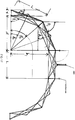
- the subtended angle will range between 90° for two BB quads (See Figure 18 ) to 25.7° for seven BBBBBBB quads (See Figure 25 ).
- the subtended angle of the B quad is determined by eliminating the A quads and joining the B quads together and making the calculation as to the subtended angle accordingly.
- to determine the subtended angle of the four bases one would eliminate triangle COD (resulting from the presence of the horizontal A quad) and merge lines CN and DP to obtain four triangles, each having apexes of 45°.
- B quads AB, BC, DE and EF represent the side views of the quads, i.e., the bases of isosceles triangles. These quads define the arcuate shape of the shelter.
- a straight line representation of a horizontal A quad, line segment CD Lines connecting center point N with vertices A, B, and C are of equal length, as are lines connecting center point P with vertices D, E and F.
- multiple isosceles triangles as shown at ANB, BNC, DPE and EPF define the arch curvature. The subtended angle is 45°.
- the A quad merely provides width to the shelter.
- the quad comprises hubs and struts that form its perimeter.
- four sets of two cross member struts each set secured at "scissor points" and situated within the interior confines of the perimeter of a quad.
- This portion of the quad is called a "sub-assembly.”
- Each of the set of struts in the sub-assembly is connected to one of the set of four corner perimeter hubs at one end, and to the two central hubs within each A and B quad at the other end.
- the struts within the sub-assembly bisect each corner thereof at 45°.
- the scissor points mentioned above play an essential role in expanding and contracting the shelter.
- the A quad has the scissor point located at the center of the strut lengths.
- the A quad only defines 0 and 90 degree planes.
- the B Quad has off-center scissor point along the length of the strut.
- the B quad is configured to define arches in multiple apex angles when connected. If all B quads were connected together or a combination of A and B quads connected together, the end result would be a circle.
- Figure 25A is an example of the circular end result of a plurality of B quads.
- a fixed dimension between A and B quad struts must be maintained in order for the struts to articulate.
- the sum of the distances between scissor points on the struts to the articulating hubs for both A and B Quads must be equal.
- the present invention provides a convenient way to construct a portable structure using a combination of A and B quads.
- a B quad one can obtain curvature to both sides of the structure, and through the use of the A quad one can obtain the desired height or length or both. Since the A quad adds height and length based on its given length L, and the B quads will provide the arch necessary to transition and connect the vertical (90°) with the horizontal (0°), one can easily form a structure of what size desired which is portable and easily set up and give both height and length.
- the angular relationships created by multiple isosceles triangles allows for the calculation of specific widths and heights of the structure. This principle determines how high and wide the structure will be. This is basically accomplished by using the Laws of Sine and Cosine and a given fixed length of the strut L. Given a fixed strut length L, which is the base of an isosceles triangle and a given vertex angle ⁇ , determined by dividing the number of B Quads into 180, and knowing also that the sum of the angles of a triangle must total 180, there is enough information to calculate the legs of the isosceles triangle which is essentially a one component of the width (half an arc) and the interior height.
- a new strut length L2 can be used to increase or decrease the width or height of the interior of the structure.
- the effective height of the interior is h 1 .
- This is also a leg of the isosceles triangle so h 1 d 1 .
- BBBBBBB Refer to Figures 17 and 24
- the quads can be used to create almost any size structure. As depicted in the drawings Figures 18 to 25 , the basic A and B quads can be connected together in various combinations to create an arch-like structure. Either of the quads can be any size depending upon the length of strut and the ratio of these lengths plus the positioning of the scissor point allowing the struts to articulate.
- the quads whether A or B comprise a substantially square structure having a base, two sides and a top. They are designated as an "A" quad or a "B" quad depending upon the location of the scissor points along the length of the struts of the subassembly, as explained in greater detail hereinafter.
- the struts used in a subassembly in the center of the quad contains four pairs of struts each pair having struts which are of different lengths.
- the B quads provide an angular plane between each quad in the larger expanded assembly ranging generally from 25.7° to 45° degrees. This angular range allows the quads to rise/fall and curve to obtain the substantially arcuate shape which many of the embodiments possess.
- Figure 3 depicts an oblique closeup view of two of the seven quads used to form the arcuate form noted above showing the hubs and struts in their deployed positions.
- the assembled shelter there is a plurality of articulating hub assemblies connected to tubular struts.
- Each quad possesses 8 articulating hub assemblies, wherein some of the articulating hub assemblies located at an end of the quad may be shared by the quad(s) located contiguous therewith.
- Figure 3 depicts an illustration of a "B" quad secured to an "A" quad end to end, i.e., base to top, etc. to form an elevated sequence of quads secured end to end to form a quad.
- This is the arrangement that is found in a row wherein an arching B quad is connected to a straight A quad when it forms the horizontal section of the row.
- the term "exterior” as used herein when referring an articulating hub assembly expresses a face of said hub which is on the outside (facing the elements) of the quad assembly facing the exterior plane of the shelter to be covered with the exterior cover of the shelter.
- an articulating hub assembly expresses a face of said hub which is on the inside (facing the interior of the shelter) of the quad assembly facing the plane to be covered with an interior cover used to form an interior "wall" of the shelter.
- the "A" quad is depicted as the top quad of the figure.
- the "A" quad depicted has a base, a pair of first and second exterior base side hubs aligned evenly in a vertical plane with respect to each other and a pair of first and second interior base side hubs aligned evenly in a vertical plane with respect to each other.
- Figure 3 depicts the "A" shelter as the top quad of the two quad structure with the "B" quad interconnected via shared articulating hubs 306, 307, 308 and 309, which quad "A” and quad “B” share.
- the arrangement depicted in Figure 3 provides a detailed view of a BAB shelter obviously with a "B” quad missing.
- Figure 3 depicting the arrangement of an "A" quad and a “B” quad is for illustrative purposes only and serves to detail the various struts and hubs and how the scissor points differ between the "A” and “B” quads.
- the positions of the quads are reversed wherein the "A" quad is on the bottom or on contact with the planar surface (i.e. the ground or surface whereupon the shelter is struck) and the "B" quad is attached to the "A" quad via the exterior and interior articulating hubs which the "A" quad shares with the "B” quad.
- first exterior base side hub 306 and said first interior base side hub 307 being in substantial in-line alignment with respect to each other and a second exterior base side hub 308 and a second interior base side hub 309 being in substantial in-line alignment with respect to each other; and a first tubular strut 360 connecting said first exterior base side hub 306 with said second interior base side hub 309; and a second tubular strut 361 connecting said second exterior base side hub 308 with said first interior base side hub 307; tubular struts 360 and 361 are adjacent to each other and extend diagonally at the base between the exterior side hubs 306, 308 and interior side hubs 307, 309 and being joined at a scissor point 396 substantially in the center of the length of each said strut.
- the "A" quad has a top side comprising a pair of first 300 and second 302 exterior top side hubs aligned evenly in a vertical plane with respect to each other and a pair of first 301 and second 303 interior top side hubs aligned evenly in a vertical plane with respect to each other.
- the first exterior top side hub 300 and the first interior top side hubs 301 are in substantial in-line alignment with each other; and the second exterior top hub 302 and said second interior top hub 303 are being in substantial in-line alignment with each other.
- tubular strut 362 connecting the first exterior top side hub 300 with said second interior top interior hub 303; and a fourth tubular strut 363 connecting second exterior top hub 302 with first interior top side hub 301.
- Tubular struts 362, 363 are adjacent to each other and extending diagonally at top between said exterior top hubs 300, 302 and interior top hubs 301, 303 and are joined at a scissor point 390 substantially in the center of the length of each said struts 362, 363.
- the first side of quad "A” comprises a pair of tubular struts 364, 365 adjacent to each other.
- a first first-side strut 364 extends diagonally between said first exterior base side hub 306 and said first interior top side hub 301, and a second first side strut 365 extends diagonally between first interior base side hub 307 and first exterior top side hub300, said first side struts 364, 365 are joined at a scissor point 391 substantially in the center of the length of each said strut;
- the second side of quad "A" comprises a pair of tubular struts 398, 399 adjacent to each other.
- a first second-side strut 399 extends diagonally between said second exterior base side hub 308 and second interior top side hub 303, and a second second side strut 398 extending diagonally between second interior base side hub 309 and second exterior top side hub 302, the second side hubs being joined at a scissor point 392 substantially in the center of the length of each said strut.
- the "A" quad further has a subassembly contained within the area defined by the top, base and sides thereof.
- the subassembly has a pair of center hubs 304, 305 comprising an exterior center hub 304 and an interior center hub 305 positioned substantially in-line substantially in the center of said quad with respect to each other, wherein four sets of two tubular struts each extend from said center hubs to said top and said base hubs.
- the "A" quad subassembly includes four sets of struts which extend radially outward from each of the two center hubs and are connected to the hubs located at the base and top corners of the quad.
- first center strut 367 connects first exterior base hub 306 to interior center hub 305
- second center strut 368 connects first interior base hub 307 to said exterior center hub 304
- first and second tubular struts 367 and 368 being adjacent to each other and extending diagonally and being joined at a scissor point 380 substantially in the center of the length of first and second struts 367 and 368.
- a third center strut 369 connects second exterior base hub 308 to interior central hub 305 and a fourth center strut 370 connects second interior base hub 309 to exterior central hub 304, the third and fourth tubular struts 369 and 370 being adjacent to each other and extending diagonally and being joined at a scissor point 381 substantially in the center of the length of the third strut 369 and said fourth strut 370.
- a first tubular strut 318 connects first exterior base side hub 313 with second interior base side hub 315 and a second tubular strut 319 connects a second exterior base side hub 314 with first interior base side hub 312.
- Tubular struts 318 and 319 are adjacent to each other and extend diagonally at the base between said exterior side hubs 313 and 314 and interior side hubs 312 and 315 and are joined at a scissor point 394 substantially in the center of the length of each strut.
- the "B" quad has a top comprising a pair of first and second exterior top side hubs aligned evenly in a vertical plane with respect to each other and a pair of first and second interior top side hubs aligned evenly in a vertical plane with respect to each other.
- the top of the "B” quad also serves as the base of the "A" quad described above.
- the first exterior top side hub 306 and first interior top side hub 307 are in substantial in-line alignment with each other, i.e.the interior substantially behind the exterior hub; and said second exterior top hub 308 and said second interior top hub 309 are in substantial in-line alignment with each other.
- a third tubular strut 360 connects the first exterior top side hub with said second interior top side hub and a fourth tubular strut 361 connects second exterior top hub 308 with said first interior top side hub307.
- Tubular struts 360 and 361 are adjacent to each other and extend diagonally at said top between said exterior top hubs 306 and 308 and interior top hubs 307 and 309 and are joined at a scissor point 396 substantially in the center of the length of each strut.
- a second side of the "B"quad comprises a pair of tubular struts 350 and 351 adjacent to each other, a first second-side strut 350 extends diagonally between said second exterior base side hub 314 and said second interior top side hub 309, and a second second side strut 351 extends diagonally between said second interior base side hub 315 and said second exterior top side hub 308, said second side struts being joined at a scissor point 393 substantially in the center of the length of each said strut;
- the "B" quad also has a subassembly contained within the area defined by top, base and sides of the quad.
- the subassembly has a pair of center hubs 310 and 311, comprising an exterior center hub 311 and an interior center hub 310 positioned substantially in-line (i.e. the interior hub substantially directly behind the exterior center hub) and substantially in the center of said quad with respect to each other.
- a strut of any length can be used to achieve specific width and height objectives.
- Figure 3 shows the positioning of end hubs 300, 301, 302, 303, 306, 307, 308, 309, 312, 313, 314 and 315. It further depicts the locations of hubs 304, 305, 310 and 311 located in the center of the square quad.
- the hubs all have threaded openings through their centers which can accommodate mushroom shaped "keepers," an example of which is shown as 330 with the threaded extension at 331 with external loops 321. Threaded element 331and keeper 330 threadedly secure the canvas fabric covering the strut matrix to the hub, and provide a means to anchor the shelter to a convenient ground surface. Keepers with external loops, such as denoted at 308, 313, 314, 320 all serve to secure the cover in place over the matrix.
- Figure 4 is an exploded view of a portion of the quad depicted in Figure 3 showing the spatial relationship of the interior side of hub 4410 with its superior side 4411, tubular struts 4420, fabric 4400, keeper component 4413 and external loop 4414. This is a closeup view of the hubs and struts which form the quads depicted in Figure 3 .
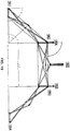
- Figure 5 depicts a front cross sectional view of an erected shelter assembly 500 of the present invention without the end assembly section arch. This is an ABBABBA shelter. There are seven quadrants depicted extending counterclockwise from I to VII. Quads I, IV and VII are A quads and quads II, III, V and VI are B quads. The connection of these quads "A” and "B” is shown in Figure 3 .
- Figure 5 includes floating hub assemblies 501 and 502. In the center of the structure is a riser 503 located at the top center of shelter assembly.
- the prior art version of the assembly would not include the floating hub but instead includes partially shown fabric covering 504, which would be connected at riser 503 and to one of the articulating hub assemblies (of the type described in the Prusmack references cited above) positioned at 505. And therein lies the problem. With the occurrence of rain or snow, the fabric, extending downward from riser 503 would eventually start to sag under the weight of same. As a result of the sagging condition, a dangerous trough eventually would form on the fabric cover allowing water or ice to collect and thereby exceeding the mandated weight load of 10 lbs/ft 2 for such structures at the location in question.
- FIG. 5 depicts two floating hub assemblies 501 and 502 of the present invention.
- the base 506 of the floating head assembly is attached to a connecting rod 508 which slides through a center opening in articulating hub assembly 505.
- Articulating hub 505 provides a platform for the floating hub to move concurrently up and down as it moves up upon expansion or down upon retraction of the shelter.
- top 509 At the opposite end of the base of the floating hub assembly and attached to connecting rod 508 is top 509. Fabric 507 is attached to riser 503 and to top 509 of the floating hub.
- the floating hub unit of base 506, connecting rod 508 and top 509 creates an extended point to attach the fabric cover and form a tight downwardly sloped surface allowing rain, ice and snow to slide off the top of the shelter assembly and down the sides.
- sloped quads II and III and V, VI
- quads two on each side of the structure which extend upwardly form vertical A quads to join and be fixedly attached to horizontal quad IV which is parallel to the ground/base beneath it.
- riser 503. The structure is generally erected outdoors and is thus exposed to the elements.
- the geometry of quads III through V dictate that rain water, or snow will descend down the sides of fabric covered quads. Because quads III and V have little slope associated with each of them with the riser and cover in place, they will tend to collect rain/snow and eventually sag under the weight of the rain or snow.
- Riser 503 is situated in the center of quads III and V to provide an apical plane above quads III and V so that the rain or snow will not collect on the surface of the fabric above quads III and V.
- the fabric covering quads III and V beneath riser 503 would eventually collect rain water or snow since there was a substantial distance between the top of riser 503 and points down slope of the deployed structure.
- the floating hubs 501 and 502 of the present invention provide a smooth upward transition on the fabric surface of the deployed structure so forming a taut surface so that no rain or snow collects above quads III and V.
- Figure 6A is a magnified oblique view of the top of the floating hub as it appears when the structure is fully erected (as shown in Figure 5 ).
- Base 606 is attached to connecting rod 608 which upon expansion of the shelter has slideably passed through the center opening in articulating hub 605.
- Top 609 is attached to connecting rod 608 at the end opposite of base 606.
- Base 606 rests upon articulating hub assembly 607 which is elevated into contact with the underside of base 606 during the procedure of raising the shelter assembly into an erected state.
- Figure 6A also shows the struts 610 which are connected to hub 605 and struts 611 which are connected to hub 607.
- hub 607 Before the shelter is set up in place, hub 607 is position at the bottom of the bundled assembly. When the assembly is set up, hub 607 is raised until it comes in contact with base 606 and upon further set up procedure, hub 607 pushes the floating hub assembly into position above the top plane of the shelter.
- Figure 6B is a magnified oblique view from a different vantage point of the same assembly depicted in Figure 6A .
- Base 606 is attached to connecting rod 608 which has slideably passed through the center opening in articulating hub 605.
- Top 609 is attached to connecting rod 608 at the end opposite of base 606.
- Base 606 rests upon articulating hub assembly 607 which is elevated into contact with the underside of base 606 during the procedure of raising the shelter assembly into an erected state.
- This action allows the tubular strut to move from a tension position with the assemblies above ground, back to a static position and collapse down to the original location on the ground.
- the appropriate diameter of the hub is a function of the size of the deployable structure to be assembled as discussed.
- the hubs are of different sizes depending upon the dimension of the shelter in which they are used.
- One embodiment of a hub has an octagonal shape which allows larger diameter tubular struts of 1 inch or greater which are fixed in the slots in the hub to rotate when erecting or collapsing the structure.
- the slots in the hubs in such case, which allow the tubular struts to be secured in the hub are offset at a 45° angle so that the struts easily fold in on themselves and provide a compact bundle for storage or expand easily for a quick set-up.
- Figure 7 is a top view of the shelter 700 of the present invention fully erected.
- the shelter structure of the present invention is formed from quads wherein a four sided rectangular or square section in combination with others form an arch.
- Arches 701, 702 and 703 comprise three interconnected arches of seven quads each forming three separate rows. Viewing from the top along the horizontal plane, the individual interconnected quads located side by side (in this case three quads each) form a column.
- floating hubs, 704, 705, 706 and 707 are located at the apexes of center quad 708 located in center arch 702.
- Risers 709, 710 and 711 are positioned in the center quad of each arch.
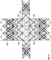
- Figure 8 is a top view of the shelter 800 of the present invention partially erected.
- the shelter structure is formed from quads to form an arch.
- Arches 801, 802 and 803 each comprise seven interconnected quads connected to form an array (column) of arches three deep.
- the struts 815, depicted in Figure 8 are not fully extended and are folded back on the hubs.
- Figure 23 depicts a modification of the shelter depicted in Figure 20 , the modification being the addition of two vertical A quads on opposing sides of the shelter.
- Two B quads on each side of the center line (BBBB) form a row/arch. Note this arrangement of quads requires a riser and floating hubs and provides more elevation than obtained in other arrangements. A plurality of these arches then can be connected together side by side to form a three-dimensional structure.
- Figure 23 illustrates a front cross-sectional view of the shelter having two A quads 2301 to 2302 and 2306 to 2307. These two A quads (2301-2302 and 2306-2307) are vertical and provide the raised sides to the shelter. The B quads flow arcuately from and to the base A quads. to the base plane.
- Figure 23 indicates that the angle between a vertical plane and a line segment connecting the exterior hub at 2302 and the shared hub at 2303 is 22.5° and the angle between a vertical plane and a line segment connecting the exterior shared hub at 2303 and the exterior shared hub at 2002 is 67.5°. These two angles total 90° which is the arc generated by the positioning of the two quads passing from the top of the A quad 2302 to the vertical plane extending from the base surface through the center top of the shelter.
- This shelter has A floating hub 2308 extending up through hub 2304. Risers 2309 are present on each side of floating hub 2308.
- a preferred embodiment of the present invention is a seven quad arch shelter.
- a shelter having a plurality of rows comprised of seven quads results in a shelter that is most desirable when used as a tactical support headquarters or hospital or other uses where interior space is needed.
- 7 quad shelter options there are three most preferred are set forth hereinafter.
- the shelter has seven quads total, comprising four "B" Quads and three "A" Quad (ABBABBA).
- This arrangement of quads requires a riser 2409 and two floating hubs 2410 and provides more width to the shelter than other seven quad arrangements.
- the hubs comprising the vertical A quads extend between 2401-2402 and 2407 and 2408 and between 2404 and 2405 in the horizontal plane.
- the B quads extend between 2001 and 2002; 2002-2003; 2003-2004 and 2004-2005.
- Figure 24 indicates that the angle between a vertical plane and a line segment connecting the shared exterior hub at 2402 and the shared hub at 2404 is 22.5° and the angle between a vertical plane and a line segment connecting the exterior shared hub at 2403 and the exterior shared hub at 2404 is 67.5°. These two angles total 90° which is the arc generated by the positioning of the two quads passing from the horizontal plane at base level to the vertical plane extending from the base surface through the center top of the shelter.
- Figure 25 depicts seven B Quads (BBBBBBB) extending from 2501 - 2502; 2502 - 2503; 2503 -2504, 2505 - 2506, 2506 - 2507 to 2507 - 2508 which flow arcuately from the horizontal base plane.
- BBBBBBB B Quads
- B quads which provide the arcuate shape to the structure.
- the structure depicted in Figure 25 shows riser 2509. No floating hub is necessary in this configuration.
- the BBBBBBB quad frame arrangement shown in Figure 25 with the riser has an adequate pitch down from the riser so the floating hub, while it could be used, is not absolutely necessary.
- the shelters ABBABBA and BBBABBB, shown in Figures 23 and 24 require the floating hub to sharpen the pitch of the fabric so it will not collect snow or ice.
- the slope or pitch of the BBBBBBB Quad shown in Figure 25 is adequate enough to prevent snow/ice build up on the fabric.
- the other two shelters depicted in Figures 24 and 26 have a flat A quad in the center which dampens the pitch from the riser so the floating hub mitigates the problem of collecting ice or snow.
- Figure 26 depicts one A quad extending from 2604 to 2605 and six B Quads extending from 201 - 2502; 2502 - 2503; 2503 -2504, 2505 - 2506, 2506 - 2507 to 2507 - 2508 (BBBABBB) which flow arcuately from the horizontal base plane to the A quad at 2604 and then from A quad 2605 down to the horizontal base plane.
- BBABBB B Quads extending from 201 - 2502; 2502 - 2503; 2503 -2504, 2505 - 2506, 2506 - 2507 to 2507 - 2508
- Figure 26 indicates that the angle between a vertical plane and a line segment connecting the shared exterior hub at 2601 and the shared hub at 2602 is 15° and the angle between a vertical plane and a line segment connecting the exterior shared hub at 2602 and the exterior shared hub at 2603 is 45°, and the angle between a vertical plane and a line segment connecting the shared exterior hub at 2603 and the shared hub at 2604 is 75°.
- the shelters ABBABBA and BBBABBB, shown in Figures 23 and 24 require the floating hub to sharpen the pitch of the fabric so it will not collect snow or ice.
- the slope or pitch of the BBBBBBB Quad shown in Figure 25 is adequate enough to prevent snow/ice build up on the fabric.
- the other two shelters depicted in Figures 24 and 26 have a flat A quad in the center which dampens the pitch from the riser so the floating hub mitigates the problem of collecting ice or snow.
- Quads disclosed in Figures 18 - 20 use 5/8" OD tubing with a circular hub with a diameter of 2 1 ⁇ 4" as disclosed in United States Patent 5,797,695 to A. Jon Prusmack
- the quads depicted in Figures 21-25 will span a greater width and therefore require a larger diameter tube.
- the larger diameter tube will have a different size hub.
- certain shelters have a 3 ⁇ 4" OD Tube and an octagon shaped hub with a width of 3".
- Another shelter has a 1" OD Tube also with an octagon shaped hub with a width of 3 5/8 .”
- Another key feature in converting the matrix frame to a shelter assembly is securing the fabric covers (covering the tubular frame network) to the articulating hub assembly body and allow the two fabric covers (interior and exterior) to move simultaneously with the tubular frame upon either set-up or fold-up.
- the cover can be any suitable fabric such as canvas, nylon, polyester, etc., and can be impregnated with fire retardants, insect repellants, etc.
- a mushroom shaped "keeper" component with a screw-type stem is secured through an opening in the articulating hub assembly to attach the fabric layers thereto.
- the present invention relates to a deployable shelter and an articulating hub assembly which serves to connect tubular rods that comprise the basic construction elements for a prefabricated, self-supporting, deployable structure.
- Figure 27 depicts tubular struts 150 and two hubs 8 and 9 of the present invention, with the tubular struts in their intermeshed orientations when the structure is in a folded state.
- the "bottom" element, 10, of hub assembly 8 is shown connected to four tubular struts
- the "top” element, 11, of hub assembly 9 is shown also connected to four tubular struts.
- the tubular struts are connected to the hub by means of a plug 151 affixed within the interior of tubular strut 150. Plug 151 is connected to tang 154 which is held within the hub body 8.
- Figure 27 shows only 7 struts for clarity.
- Figure 28 shows the "bottom" 10 of hub assembly 8 of the present invention, with four tubular struts 150 in their folded and intermeshed positions. Similar to Figure 27 , the tubular struts 150 are fastened to plug 151 which is, in turn, fastened to tang 154 which is captured within hub body 8 as is described in further detail below.
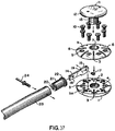
- Figure 29 is an orthogonal exploded view of the articulating hub assembly of the present invention depicting the bottom 10 and top 20 sections of the hub body with the connecting end of tubular struts 150 and 270 of the skeletal matrix as well as other relevant parts shown in their respective locations when the assembly is in use.
- plug 151 within the end of tubular strut 150 is fastened plug 151 with the assistance of ribs 152.
- Plug 151 is generally and preferably cylindrical in shape and has a crown 157 at one end which rests against shoulder 158 when assembled.
- the diameter of the portion of plug 151 beyond crown 158 is substantially the same as the inside diameter of the tubular strut elements which form the skeletal matrix of the shelter.
- a rivet (not shown) secures tang tail 153 in plug 151 to the tubular element (not shown).
- Head 159 of tang 154 is wider than tail 153 and merges therewith at shoulder 168.
- Tang 154 is captured within the hub assembly by means of roll pin 330 which is inserted through opening 156 in tang 154.
- Roll pin 330 is captured within groove 200 (shown in Figure 31B ) in hub bottom 10 so that tang 154 is captured by hub 8 but able to move within slits 160 and 170 in hub bottom 10 and top 20, respectively. Slits 160 and 170 are in registered alignment.
- tang 154 having a head 159 and a tail 153.
- Tang 154 is inserted through a plug 151 which is also inserted within the end of tubular strut 150.
- Tang 154 is held in place within hub bottom 10 by roll pin 330 which is inserted through an opening 156 through head 159.
- Roll pin 330 is secured in a groove (not shown in Figure 29 but shown in Figure 29 ) in the underside of hub bottom 10. (See Figure 31B .)
- Tail 153 of tang 154 is sufficiently long to extend radially outward from radial slits 160 and 170.
- Tail 153 of tang 154 possesses a width substantially the same as is present in a slit that extends radially through plug 151.
- Hub bottom 10 has seven slits analogous to slit 160 (161 through 167), and hub top 20 has seven slits analogous to slit 170 (171 through 177), in registered alignment with the slits in the hub bottom.
- openings 180 through 187 are recessed and are in registered alignment with openings 210 to 217 in hub top 20.
- Each opening 180 through 187 and 210 to 217 receives a means for securing bottom 10 and hub top 20.
- the securing means is a fastener 280 through 287, not shown in this view. Openings 180 through 187 in the hub bottom 10 , and 210 to 217 on the top 20 are preferably recessed so the heads of the fasteners and the nuts (not shown) lie flush with the respective surfaces of the hub. The nuts and fasteners referred to are tightened to secure hub top 20 to hub bottom 10.
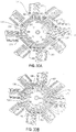
- Figure 32A is a plan view of the top surface of the assembly depicted in Figure 29 showing some of the elements detailed in Figure 29 , including the octagonal shape of hub top 20 of hub assembly 8.
- Figure 32A includes hub assembly 8 with eight tubular struts each with a plug, as illustrated by element 151, and tang 154, each tang inserted within a slit as illustrated by element 160.
- each strut is connected to hub 8 by means of tangs 154, 272 and 300 to 305 which in turn engage plugs 151, 271 and 307 to 312.
- the view shows eight fasteners as illustrated by elements 280 to 287 which are used to secure, in combination with eight fasteners (not shown) the superior element to the inferior element comprising the hub.
- Keeper 260 is fixed to the hub using any suitable means, and a loop 290, to hold wind lines, is secured to central well 263 of keeper 260 by any suitable means.
- the loop is generally permanently attached to keeper component 260.
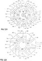
- Figure 32B is a plan view of the bottom surface of the assembly depicted in Figure 29 showing some of the elements detailed in Figure 29 including the octagonal shaped hub bottom 10 of hub assembly 8 as it is used in combination with tubular struts the comprise the matrix of the deployable structure in the erected state.
- Figure 32B includes hub assembly 8 with eight tubular struts 150, 270, 313 to 318 each within a slit as illustrated by elements 160 to 167.
- Struts 150, 270 and 313 to 318 are engaged to the hub by means of tangs 154 and 300 to 305 which are in turn engaged with plugs 152, 271 and 307 to 312.
- Hub bottom 10 has a central, threaded opening 250, within which is threadedly engaged the shaft 262 of the keeper 260.
- Hub bottom 10 has nuts, 230 to 237, which threadedly engage fasteners 280 to 287 (the tip of which are shown protruding through the center of nuts 230 to 237) to secure hub bottom 10 to hub top 20.
- the protruding tip 313 of hub keeper 260 appears in the opening in the center of the hub.
- hub 8 comprising the present invention therefore is an octagonal unit made up of two separable sections, hub bottom 10 and a hub top 20 (See also Figure 31A and Figure 31B ).
- Figure 29 specifically depicts the superior side of hub bottom 10 and the inferior side of hub top 20.
- hub 8 contains 8 peripheral edges 101 to 108 which are continuously connected, each to the next, around its periphery thus forming 8 vertices each subtending an angle of 45°.
- the angle is 45°.
- slits 160 through 167 and 170 to 177 are cut normal to the peripheral edge in question into hub 8 in direct alignment through hub bottom 10 and hub top 20 that comprise hub 8.
- Each of the aforementioned 8 vertices formed by the intersecting edges 101 through 108 around the periphery subtends an angle of 45°. Accordingly, proceeding in a clockwise manner around the octagonal periphery of the hub with its defined sections, the adjacent slits cut into the hub each form an angle of 45° with the succeeding and preceding edges.
- Figure 31A depicts a plan view of hub assembly 8 showing, in a partial cut-away view, hub top 20 and hub bottom 10. Shown are the struts, 150, 270 and 313 to 318, each connected by way of a plug, 151, 271, 307 to 312, respectively, to a tang, 154, 272, 300 to 305, respectively, which is captured within the hub top 20 by means of a roll pin captured within a groove (not shown).
- the hub top 20 is secured to hub bottom 10 by means of a fastener, two of which are shown in this representation, 281 and 282.
- the cut-away portion of the drawing shows two of the eight wells 326 and 327 in hub bottom 10 as well as two of the eight openings 184 and 185 in hub bottom 10.
- Figure 31B depicts a plan view of hub assembly 8 showing, in a partial cut-away view, hub bottom 10 and hub top 20. Shown are struts 150, 270 and 313 to 318, each connected by way of a plug, 151, 271, 307 to 312, respectively, to a tang, 154, 272, 300 to 305, respectively, which is captured within the hub top 20 by means of a roll pin, two of which, 330 and 331, are shown. The roll pins, 330 and 331 are shown, are captured within hub top 20 by means of a groove, grooves 200 and 201 are shown. The hub top 20 is secured to hub bottom 10 by means of fasteners each of which is threadedly secured by a nut. In this view six nuts, 230 to 235, are shown. The cut-away portion of the drawing shows two of the eight wells 340 and 341 in hub top 20 as well as two of the eight openings 210 and 211 in hub top 20.
- Figure 30A depicts a plan view of a hub bottom of a second example of the invention.
- the hub bottom 400 which has eight edges, 410 to 417 and eight slits, 420 to 427. Perpendicular to each slit is a groove, 430 to 437, for the purpose of capturing the roll pins (not shown) of the tangs (not shown).
- the hub bottom has eight interior wells, 440 to 447, and eight exterior wells, 450 to 457, to facilitate manufacture and improve the structural properties of the component.
- Hub bottom 400 has a central opening 401 which is threaded on its interior surface. The central opening is within a boss 402. Hub bottom is also provided with eight openings, 460 to 467, for fasteners (not shown).
- Figure 31A which describes example 1 of the present invention.
- Figure 32A which describes Example 2 of the present invention has analogous relationships. Referring to Figure 32A , slits 160 and 170 are aligned and positioned normal to edge 106; likewise slits 161 and 171 are positioned normal to edge 107; likewise slits 161 and 172 are positioned normal to edge 108, and so it continues around the periphery of the octagonal hub.
- each pair of slits (e.g., 160/170, 161/171 and 162/172) which are normal to their particular edge (106, 107 and 108 respectively) form an angle with the preceding and succeeding slits.
- the slits in the hub are all positioned at angle of 45° with respect to one another.
- Figure 33A and Figure 33B depict plan views (not drawn to scale) of the interior surface of the bottom half of the improved "M" hub of the present invention ( Figure 33A ) and the interior surface of the top half ( Figure 33A ) of the improved "M" hub of the present invention.
- Figure 35A depicts a side view of the hub assembly 8, comprised of top 20 and bottom 10, showing only two sets of struts 150 and 270, plugs 151 and 271 and tangs 154 and 272, for clarity. Also shown is loop 109 captured within keeper 260 by knot 110. Keeper 260 is shown in its assembled position threadedly secured to hub bottom 10.
- Figure 36A is a side view of the improved "M” hub of the present invention.
- Figure 36B is a cutaway cross sectional view of the improved "M" hub of the present invention.
- Figure 39 depicts a side view taken along the line 5--5 of Figure 38 of the octagonal embodiment showing hub body 1A, hub cover 6A and keeper 11A.
- keeper 11A possesses a top 12A which is a rectangular shaped head having a depression head 50 therein.
- the purpose in having a depression is to enable the construction crew to insert and remove the keeper easily. Any shape keeper will be effectively used.
- keeper 11A comprises top 12A having a depression area 50 therein and shaft 51 which extends into the flexible end sections 52 and 53 which serve as connectors and which are flexible and capable of splaying and locking into openings 54 and 55 located on the underside of hub body 1A.
- the keeper secures hub cover and hub body together as a result of the shaft section extending through the central opening in the hub cover and the hub body, with the tip ends of the flexible connectors fixed into openings 54 and 55.
- All the components comprising the deployable shelter described hereinabove are interchangeable.
- the hub sections are joined together using screws making replacement a simple step.
- the tubes can be individually replaced without having to remove the entire collection of tubes before the individual tube in the collection is replaced such as is the case in the prior art.
- the method for erecting the shelter is a multi-step process.
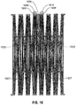
- the collapsed bundle of hubs and struts, with covers (exterior and interior) attached comprising the present invention as depicted in Figures 15 and 16 with the cover not shown, is placed on the ground or some other suitable surface where the structure will be erected.
- Figure 16 shows the unit to be erected without the fabric cover.
- the interior cover of the shelter has a Velcro system for attaching a fabric floor to the sides of the fabric cover to provide a totally enclosed area.
- Figure 14 depicts the two end arches. Looking from the top of Figure 14 , the perimeter of the main structure of the shelter has three rows of quads nested adjacent to one another.
- the bundled structure as described above, with the cover attached to the unit is placed in the center of the floor element.
- Four personnel are positioned - -two on each side, and two at each end of the bundled unit and the apical hub is gripped and then simultaneously lifted up and pulled out until the all of the hubs are in line with one another.
- the unit will rise and fall freely when fully spread out.
- the four ingress/egress areas which will become the doorway are marked as "telltale" hubs. Personnel position themselves under these "telltale” hubs and unifiedly lift upward. When the unit has been raised, a pole for lifting the shelter higher is temporarily placed under each of the "telltale" hubs by the doorways.
Landscapes
- Engineering & Computer Science (AREA)
- Architecture (AREA)
- Civil Engineering (AREA)
- Structural Engineering (AREA)
- Physics & Mathematics (AREA)
- Electromagnetism (AREA)
- Tents Or Canopies (AREA)
- Joining Of Building Structures In Genera (AREA)
- Steps, Ramps, And Handrails (AREA)
Claims (15)
- Zusammenlegbare, ortsbewegliche, selbstragende Konstruktion, umfassend:mehrere miteinander verbundene Streben, die mit mehreren äußeren und inneren gelenkigen Nabenanordnungen verbunden sind, wobei die Nabenanordnungen als Schwenkmittel dienen, die ermöglichen, die Streben, die in den Naben befestigt sind, an der Nabe um 180° um eine senkrechte Achse zu drehen, wobei die Streben und die Nabenanordnungen, die miteinander verbunden sind, ein quadratisches Viereck bilden, wobei ein Unterstand aus mindestens zwei B-Vierecken gebildet wird, wobei die B-Vierecke, die den Unterstand bilden, miteinander verbunden sind und sich gemeinsame äußere und innere Naben an der Oberseite und der Basisseite von jedem der B-Vierecke teilen, mit Ausnahme der Basis eines "B-Vierecks", die mit einer ebenen Oberfläche in Kontakt steht,wobei das "B"-Viereck eine Basisseite aufweist, die umfasst:ein Paar aus einer ersten und einer zweiten äußeren Basisseitennabe (313, 314), die in Bezug aufeinander in einer senkrechten Ebene gleichmäßig ausgerichtet sind, und ein Paar aus einer ersten und einer zweiten inneren Basisseitennabe (312, 315), die in Bezug aufeinander in einer senkrechten Ebene gleichmäßig ausgerichtet sind,wobei die erste äußere Basisseitennabe (313) und die erste innere Basisseitennabe (312) in Bezug aufeinander im Wesentlichen in einer Linie in Ausrichtung sind und die zweite äußere Basisseitennabe (314) und die zweite innere Basisseitennabe (315) in Bezug aufeinander im Wesentlichen in einer Linie in Ausrichtung sind, undeine erste rohrförmige Strebe (318), welche die erste äußere Basisseitennabe (313) mit der zweiten inneren Basisseitennabe (315) verbindet,eine zweite rohrförmige Strebe (319), welche die zweite äußere Basisseitennabe (314) mit der ersten inneren Basisseitennabe (312) verbindet,wobei die erste und die zweite rohrförmige Strebe (318, 319) einander benachbart sind und sich diagonal an der Basis zwischen den außenseitigen Naben (313, 314) und den innenseitigen Naben (312, 315) erstrecken und an einem Scherenpunkt (394) im Wesentlichen in der Mitte der Länge jeder aus der Gruppe umfassend die erste und die zweite rohrförmige Strebe (318, 319) verbunden sind,wobei das "B"-Viereck eine Oberseite aufweist, die umfasst:ein Paar aus einer ersten und einer zweiten äußeren Oberseitennabe (306, 308), die in Bezug aufeinander in einer senkrechten Ebene gleichmäßig ausgerichtet sind, und ein Paar aus einer ersten und einer zweiten inneren Oberseitennabe (307, 309), die in Bezug aufeinander in einer senkrechten Ebene gleichmäßig ausgerichtet sind,wobei die erste äußere Oberseitennabe (306) und die erste innere Oberseitennabe (307) im Wesentlichen in einer Linie in Ausrichtung miteinander sind, und wobei die zweite äußere Oberseitennabe (308) und die zweite innere Oberseitennabe (309) im Wesentlichen in einer Linie in Ausrichtung miteinander sind, undeine dritte rohrförmige Strebe (360), welche die erste äußere Oberseitennabe (306) mit der zweiten inneren Oberseitennabe (309) verbindet,eine vierte rohrförmige Strebe (361), welche die zweite äußere Oberseitennabe (308) mit der ersten inneren Oberseitennabe (307) verbindet, wobei die dritte und die vierte rohrförmige Strebe (360, 361) einander benachbart sind und sich diagonal an der Oberseite zwischen den äußeren Oberseitennaben (306, 308) und den inneren Oberseitennaben (307, 309) erstrecken und an einem Scherenpunkt (396) im Wesentlichen in der Mitte der Länge jeder aus der Gruppe umfassend die dritte und die vierte rohrförmige Strebe (360, 361) verbunden sind,wobei eine erste Seite des "B"-Vierecks ein Paar voneinander benachbarten rohrförmigen Streben (316, 317) umfasst, eine erste erstseitige Strebe (316), die sich diagonal zwischen der ersten äußeren Basisseitennabe (313) und der ersten inneren Oberseitennabe (307) erstreckt, und eine zweite erstseitige Strebe (317), die sich diagonal zwischen der ersten inneren Basisseitennabe (312) und der ersten äußeren Oberseitennabe (306) erstreckt, wobei die erstseitigen Streben (316, 317) an dem Scherenpunkt (395) im Wesentlichen außerhalb der Mitte der Länge jeder aus der Gruppe umfassend die erste erstseitige Strebe (316) und die zweite erstseitige Strebe (317) verbunden sind,wobei eine zweite Seite des B-Vierecks ein Paar voneinander benachbarten rohrförmigen Streben (350, 351) umfasst, eine erste zweitseitige Strebe (350), die sich diagonal zwischen der zweiten äußeren Basisseitennabe (314) und der zweiten inneren Oberseitennabe (309) erstreckt, und eine zweite zweitseitige Strebe (351), die sich diagonal zwischen der zweiten inneren Basisseitennabe (315) und der zweiten äußeren Oberseitennabe (308) erstreckt, wobei die zweitseitigen Streben (350, 351) an dem Scherenpunkt (393) im Wesentlichen außerhalb der Mitte der Länge jeder aus der Gruppe umfassend die erste zweitseitige Strebe und die zweite zweitseitige Strebe verbunden sind,wobei das "B"-Viereck ferner eine Unteranordnung aufweist, die innerhalb des Bereichs, der durch die Oberseite, die Basisseite und die Seiten definiert wird, enthalten ist, wobei die Unteranordnung ein Paar von Mittelnaben (310, 311) aufweist, umfassend eine äußere Mittelnabe (311) und eine innere Mittelnabe (310), die in Bezug aufeinander im Wesentlichen in einer Linie im Wesentlichen in der Mitte des B-Vierecks angeordnet sind, wobei sich vier Sätze aus je zwei rohrförmigen Streben (325, 326); (322, 323); (327, 328); (332, 333) von den Mittelnaben (310, 311) zu den äußeren und den inneren Oberseitennaben (306, 308, 307, 309) und den äußeren und den inneren Basisnaben (313, 314, 312, 315) erstrecken:a) eine erste Mittelstrebe (325), welche die erste äußere Basisnabe (313) mit der inneren Mittelnabe (310) verbindet, und eine zweite Mittelstrebe (326), welche die erste innere Basisnabe (312) mit der äußeren Mittelnabe (311) verbindet, wobei die erste und die zweite Mittelstrebe (325, 326) jeweils eine verschiedene Länge aufweisen und einander benachbart sind und sich diagonal erstrecken und an einem Scherenpunkt (343) im Wesentlichen außerhalb der Mitte der Länge der ersten und der zweiten Mittelstrebe (325, 326) verbunden sind,b) eine dritte Mittelstrebe (328), welche die zweite äußere Basisnabe (314) mit der inneren Mittelnabe (310) verbindet, und eine vierte Mittelstrebe (327), welche die zweite innere Basisnabe (315) mit der äußeren Mittelnabe (311) verbindet, wobei die dritte und die vierte Mittelstrebe (327, 328) jeweils eine verschiedene Länge aufweisen und einander benachbart sind und sich diagonal erstrecken und an einem Scherenpunkt (340) im Wesentlichen außerhalb der Mitte der Länge der dritten und der vierten Mittelstrebe (327, 328) verbunden sind,c) eine fünfte Mittelstrebe (323), welche die erste äußere Oberseitennabe (306) mit der inneren Mittelnabe (310) verbindet, und eine sechste Mittelstrebe (322), welche die erste innere Oberseitennabe (307) mit der äußeren Mittelnabe (311) verbindet, wobei die fünfte und die sechste Mittelstrebe (322, 323) jeweils eine verschiedene Länge aufweisen und einander benachbart sind und sich diagonal erstrecken und an einem Scherenpunkt (342) im Wesentlichen außerhalb der Mitte der Länge der fünften und der sechsten Mittelstrebe (322, 323) verbunden sind,d) eine siebte Mittelstrebe (333), welche die zweite äußere Oberseitennabe (308) mit der inneren Mittelnabe (310) verbindet, und eine achte Mittelstrebe (332), welche die zweite innere Oberseitennabe (309) mit der äußeren Mittelnabe (311) verbindet, wobei die siebte und die achte Mittelstrebe (332, 333) jeweils eine verschiedene Länge aufweisen und einander benachbart sind und sich diagonal erstrecken und an einem Scherenpunkt (341) im Wesentlichen außerhalb der Mitte der Länge der siebten und der achten Mittelstrebe (332; 333) verbunden sind,wobei jeder der Scherenpunkte in der Unteranordnung radial im gleichen Abstand von der Mitte der Mittelnaben (310, 311) angeordnet ist, undwobei die gelenkige Nabenanordnung einen Körper aufweist, der ausgewählt wird aus der Gruppe bestehend aus:i) starren, achteckig geformten, zusammenpassenden Komponenten, einer oberen (500) und einer unteren (400), wobei die Achteckform des Nabenkörpers durch einen Umfang definiert ist, der acht gerade Kanten (410-417, 510-517) an dem Umfang (510-517) des Nabenkörpers und acht Schlitze (420-427, 520-527) aufweist, wobei sich jeder Schlitz von dem Umfang durch die obere (500) und die untere (400) Komponente von und normal zu jeder der geraden Kanten an dem Umfang des Nabenkörpers radial einwärts erstreckt, wobei jeder Schlitz (420-427, 520-527) an einem Eckpunkt angeordnet ist, der an Kreuzungen von jeder der Kanten um den Umfang des Nabenkörpers herum gebildet wird, und wobei der achteckigen Ausgestaltung des Umfangs des Nabenkörpers entsprechend benachbarte Schlitze, die von jedem nachfolgenden und vorhergehenden Schlitz relativ zu dem Schlitz, der normal zu der Kante ist, ausgehen, in einem Winkel von 45° in Bezug darauf ausgerichtet sind, und
wobei die obere Nabenkomponente (500) durch einen Umfang (510-517), eine äußere und eine innere Oberfläche, eine mittlere Buckelaufnahmeöffnung (501), mehrere der radialen Schlitze (520-527), die sich durch die obere Nabenkomponente (500) erstrecken, und mehrere Öffnungen (540-547), die radial in Richtung des Umfangs (510-517) der oberen Nabenkomponente angeordnet sind, definiert ist, wobei die Öffnungen (540-547) angeordnet sind, um eine einzige Öffnung vorzusehen, die in jedem der zwischen zwei benachbarten der Schlitze (520-527) definierten Bereiche angeordnet ist, und angeordnet sind, um mit der Position der Öffnungen (460-467) durch die untere Nabenkomponente (400) übereinzustimmen, wenn die obere Nabenkomponente und die untere Nabenkomponente (500, 400) verbunden sind, und
wobei die untere Nabenkomponente (400), wobei jede der Kanten des Umfangs (410-417) mit den Kanten (510-517) der oberen Nabenkomponente (500) in Ausrichtung ist, eine äußere und eine innere Oberfläche, einen Buckel (402), der sich von der inneren Oberfläche der unteren Nabenkomponente (400) aufwärts erstreckt, eine mittlere Öffnung (401) in dem Buckel (402) und mehrere Öffnungen (460-467), die radial in Richtung des Umfangs der unteren Nabenkomponente (400) angeordnet sind, aufweist, wobei die Öffnungen (460-467) angeordnet sind, um eine einzige Öffnung vorzusehen, die in jedem der zwischen zwei benachbarten der Schlitze (420-427) definierten Bereiche angeordnet ist, und angeordnet sind, um der Position der Öffnungen (540-547) durch die obere Nabenkomponente (500) zu entsprechen, wenn die obere Nabenkomponente (500) und die untere Nabenkomponente (400) verbunden sind, und wobei jeder der Schlitze (420-427) in der unteren Nabenkomponente (400) eine unterbrochene Rille (430-437) aufweist, die im rechten Winkel dazu angeordnet ist und sich quer über den Schlitz (420-427) in jeden der zwischen zwei benachbarten der Schlitze (420-427) definierten Bereiche erstreckt,
wobei die obere Nabenkomponente (500) und die untere Nabenkomponente (400) aneinander angrenzend angebracht werden, derart, dass sich die mittigen Öffnungen (501, 401), die radialen Schlitze (520-527, 420-427) und die Öffnungen (460-467, 540-547) durch die obere Nabenkomponente (500) und die untere Nabenkomponente (400) erstrecken, und wobei die obere Nabenkomponente (500) und die untere Nabenkomponente (400) in Deckung sind, und
einem entfernbaren Befestigungsmittel (281), das sich durch die Öffnungen (540-547) in der oberen Nabenkomponente (500) erstreckt und in den in Deckung damit befindlichen Öffnungen (460-467) in der unteren Nabenkomponente (400) befestigt ist, und
einem einstückig ausgebildeten Halteelement (260), das ein oberes Ende und einen Schaft, der sich davon abwärts erstreckt, aufweist, wobei der Schaft durch die obere und die untere Nabenkomponente (500, 400) in die mittigen Öffnungen (401, 501) eingeführt und daraus herausgezogen werden kann, und
wobei das einstückig ausgebildete Halteelement (260) Mittel (262) aufweist, um die obere Nabenkomponente (500) an der unteren Nabenkomponente (400) zu befestigen, und
wobei jede Strebe, die in einer Nabenanordnung befestigt ist, an einem Endabschnitt davon einen zylindrischen Stopfen (151) aufweist, der in der Strebe (150) befestigt ist, wobei der Stopfen eine Öffnung aufweist, aus der sich ein Zapfen (154) erstreckt, wobei der Zapfen (154) eine erste Seite und eine zweite Seite aufweist, wobei sich ein Endabschnitt (153) und ein Kopfabschnitt (159) mit einem Spannstift (330) von der ersten Seite zu der zweiten Seite erstreckt, wobei der Kopfabschnitt (159) des Zapfens (154) in einem der radialen Schlitze in der unteren Nabenkomponente (400) mit der oberen Nabenkomponente (500) in Deckung damit angeordnet ist, wobei der Zapfen (154) durch den Spannstift (330), der in die unterbrochenen Rillen (430-437) eingreift, festgehalten wird, oderii) einem mittigen Nabenkörper (1) mit einem Umfang, einer mittigen Öffnung (2) durch diesen hindurch und mehreren radialen Schlitzen (3), die sich von dem Umfang des Nabenkörpers (1) einwärts erstrecken, wobei jeder der radialen Schlitze (3) in dem Nabenkörper (1) eine unterbrochene Rille (3A), die im rechten Winkel dazu angeordnet ist, aufweist, wobei der Nabenkörper (1) auch eine Reihe von Öffnungen (4) aufweist, die sich durch den Nabenkörper (1) erstrecken, wobei die Öffnungen (4) radial zwischen jedem der radialen Schlitze (3) und zwischen dem Umfang und der mittigen Öffnung (2) des Nabenkörpers (1) angeordnet sind,einer Nabenabdeckung (6), die einen Umfang, eine mittige Öffnung (7) durch diese hindurch, mehrere radiale Schlitze (3, 8) und eine Reihe von Öffnungen (9), die sich durch die Nabenabdeckung (6) erstrecken, aufweist, wobei der Nabenkörper (1) und die Nabenabdeckung (6) aneinander angrenzend angebracht werden, derart, dass die mittige Öffnung (7), die radialen Schlitze (3, 8) und die Öffnungen (9) der Nabenabdeckung (6) mit der mittigen Öffnung (2), den radialen Schlitzen (3) und den Öffnungen (4) des Nabenkörpers (1) in Deckung sind,entfernbaren Befestigungsmitteln (10), wobei sich die entfernbaren Befestigungsmittel (10) durch die Öffnungen (9) in der Nabenabdeckung (6) erstrecken und in den Öffnungen (4) in dem Nabenkörper (1) befestigt sind,einem einstückig ausgebildeten Halteelement (11) mit einem Oberteil (12) und einem Schaft (13), der sich davon nach unten erstreckt, wobei der Schaft (13) in die mittigen Öffnungen (2, 7) des Nabenkörpers (1) und der Nabenabdeckung (6) eingeführt und aus diesen entfernt werden kann, wobei der Schaft (13) Mittel zum Befestigen der Nabenabdeckung (6) an dem Nabenkörper (1) aufweist, wobei jede Strebe, die in einer Nabenanordnung befestigt ist, an jedem Endabschnitt davon aufweisteinen zylindrischen Stopfen (21), der in der Strebe (23) befestigt ist, wobei der Stopfen (21) eine Öffnung aufweist, aus der sich ein Zapfen (14) erstreckt, wobei der Zapfen (14) eine erste Seite und eine zweite Seite aufweist, wobei sich ein Endabschnitt (16) und ein Kopfabschnitt (15) mit einem Spannstift (17) von der ersten Seite zu der zweiten Seite erstreckt, wobei der Kopfabschnitt (15) des Zapfens (14) in einem der radialen Schlitze (3) in dem Nabenkörper (1) mit der Nabenabdeckung (6) in Deckung damit angeordnet ist, wobei der Zapfen (14) durch den Spannstift (17), der in die unterbrochene Rille (3A) eingreift, festgehalten wird. - Konstruktion nach Anspruch 1, wobei der Unterstand mit der Hinzufügung von mindestens einem A-Viereck in miteinander verbundener Kombination mit einer geraden Anzahl von B-Vierecken gebildet ist, wobei die A- und B-Vierecke eine bogenförmige Reihe bilden, die sich bogenförmig von einem ersten Viereck, das eine Basis in Kontakt mit einer ebenen Oberfläche aufweist, zu einem letzten Viereck, das eine Basis in Kontakt mit der ebenen Oberfläche aufweist, erstreckt, wobei eine Abfolge von dazwischen angeordneten Vierecken mittels gemeinsam genutzter Naben zwischen dem ersten Viereck und dem letzten Viereck miteinander verbunden sind,
wobei das "A"-Viereck eine Basisseite, eine Oberseite, eine erste Seite und eine zweite Seite aufweist, wobei jede der Seiten die Basisseite mit der Oberseite verbindet, wobei die Basis ein Paar aus einer ersten und einer zweiten äußeren Basisseitennabe (306, 308), die in Bezug aufeinander in einer senkrechten Ebene gleichmäßig ausgerichtet sind, und ein Paar aus einer ersten und einer zweiten inneren Basisseitennabe (307, 309), die in Bezug aufeinander in einer senkrechten Ebene gleichmäßig ausgerichtet sind, umfasst,
wobei die erste äußere Basisseitennabe (306) und die erste innere Basisseitennabe (307) in Bezug aufeinander im Wesentlichen in einer Linie in Ausrichtung sind und die zweite äußere Basisseitennabe (308) und die zweite innere Basisseitennabe (309) in Bezug aufeinander im Wesentlichen in einer Linie in Ausrichtung sind, und
eine erste rohrförmige Strebe (360), welche die erste äußere Basisseitennabe (306) mit der zweiten inneren Basisseitennabe (309) verbindet,
eine zweite rohrförmige Strebe (361), welche die zweite äußere Basisseitennabe (308) mit der ersten inneren Basisseitennabe (307) verbindet,
wobei die rohrförmigen Streben einander benachbart sind und sich diagonal an der Basis zwischen den außenseitigen Naben (306, 308) und den innenseitigen Naben (307, 309) erstrecken und an einem Scherenpunkt (396) im Wesentlichen in der Mitte der Länge jeder aus der Gruppe umfassend die erste und die zweite rohrförmige Strebe (360, 361) verbunden sind,
wobei das "A"-Viereck eine Oberseite aufweist, umfassend ein Paar aus einer ersten und einer zweiten äußeren Oberseitennabe (300, 302), die in Bezug aufeinander in einer senkrechten Ebene gleichmäßig ausgerichtet sind, und ein Paar aus einer ersten inneren Oberseitennabe und einer zweiten inneren Oberseitennabe (301, 303), die in Bezug aufeinander in einer senkrechten Ebene gleichmäßig ausgerichtet sind,
wobei die ersten äußeren Oberseitennaben (300) und die erste innere Oberseitennabe (301) im Wesentlichen in einer Linie in Ausrichtung miteinander sind, und die zweite äußere Oberseitennabe (302) und die zweite innere Oberseitennabe (303) im Wesentlichen in einer Linie in Ausrichtung miteinander sind, und
eine dritte rohrförmige Strebe (362), welche die erste äußere Oberseitennabe (300) mit der zweiten inneren Oberseitennabe (303) verbindet,
eine vierte rohrförmige Strebe (363), welche die zweite äußere Oberseitennabe (302) mit der ersten inneren Oberseitennabe (301) verbindet, wobei die rohrförmigen Streben (362, 363) einander benachbart sind und sich diagonal an der Oberseite zwischen den äußeren Oberseitennaben (300, 302) und den inneren Oberseitennaben (301, 303) erstrecken und an einem Scherenpunkt (390) im Wesentlichen in der Mitte der Länge jeder aus der Gruppe umfassend die dritte und die vierte rohrförmige Strebe (362, 363) verbunden sind,
wobei eine erste Seite des Vierecks ein Paar von rohrförmigen Streben (364, 365), die einander benachbart sind, umfasst, eine erste erstseitige Strebe (364), die sich diagonal zwischen der ersten äußeren Basisseitennabe (306) und der ersten inneren Oberseitennabe (301) erstreckt, und eine zweite erstseitige Strebe (365), die sich diagonal zwischen der ersten inneren Basisseitennabe (307) und der ersten äußeren Oberseitennabe (300) erstreckt, wobei die erstseitigen Streben (364, 365) an einem Scherenpunkt (391) im Wesentlichen in der Mitte der Länge jeder der Streben (364, 365) verbunden sind,
wobei eine zweite Seite des Vierecks ein Paar von rohrförmigen Streben (398, 399), die einander benachbart sind, umfasst, eine erste zweitseitige Strebe (399), die sich diagonal zwischen der zweiten äußeren Basisseitennabe (308) und der zweiten inneren Oberseitennabe (303) erstreckt, und eine zweite zweitseitige Strebe (398), die sich diagonal zwischen der zweiten inneren Basisseitennabe (309) und der zweiten äußeren Oberseitennabe (302) erstreckt, wobei die zweitseitigen Naben an einem Scherenpunkt (392) im Wesentlichen in der Mitte der Länge jeder der Streben (366, 367) verbunden sind,
wobei das "A"-Viereck ferner eine Unteranordnung aufweist, die innerhalb des Bereichs, der durch die Oberseite, die Basis und die Seiten definiert wird, enthalten ist, wobei die Unteranordnung ein Paar von Mittelnaben (304, 305) aufweist, umfassend eine äußere Mittelnabe (304) und eine innere Mittelnabe (305), die in Bezug auf einander im Wesentlichen in einer Linie im Wesentlichen in der Mitte des Vierecks angeordnet sind, wobei sich vier Sätze aus je zwei rohrförmigen Streben von den Mittelnaben zu den Oberseiten- und den Basisnaben (367, 368; 369, 370; 371, 372; 373, 374) erstrecken,a) eine erste Mittelstrebe (367), welche die erste äußere Basisnabe (306) mit der inneren Mittelnabe (305) verbindet, und eine zweite Mittelstrebe (368), welche die erste innere Basisnabe (307) mit der äußeren Mittelnabe (304) verbindet, wobei die erste und die zweite rohrförmige Strebe (367, 368) jeweils eine verschiedene Länge aufweisen und einander benachbart sind und sich diagonal erstrecken und an einem Scherenpunkt (380) im Wesentlichen in der Mitte der Länge der ersten Strebe (367) und der zweiten Strebe (368) verbunden sind,b) eine dritte Mittelstrebe (369), welche die zweite äußere Basisnabe (308) mit der inneren Mittelnabe (305) verbindet, und eine vierte Mittelstrebe (370), welche die zweite innere Basisnabe (309) mit der äußeren Mittelnabe (304) verbindet, wobei die dritte und die vierte rohrförmige Strebe (369, 370) jeweils eine verschiedene Länge aufweisen und einander benachbart sind und sich diagonal erstrecken und an einem Scherenpunkt (381) im Wesentlichen in der Mitte der Länge der dritten Strebe (369) und der vierten Strebe (370) verbunden sind,c) eine fünfte Mittelstrebe (373), welche die erste äußere Oberseitennabe (300) mit der inneren Mittelnabe (305) verbindet, und eine sechste Mittelstrebe (374), welche die erste innere Oberseitennabe (301) mit der äußeren Mittelnabe (304) verbindet, wobei die fünfte und die sechste rohrförmige Strebe (373, 374) jeweils eine verschiedene Länge aufweisen und einander benachbart sind und sich diagonal erstrecken und an einem Scherenpunkt (383) im Wesentlichen in der Mitte der Länge der fünften Strebe (373) und der sechsten Strebe (374) verbunden sind,d) eine siebte Mittelstrebe (372), welche die zweite äußere Oberseitennabe (302) mit der inneren Mittelnabe (305) verbindet, und eine achte Mittelstrebe (371), welche die zweite innere Oberseitennabe (303) mit der äußeren Mittelnabe (304) verbindet, wobei die siebte und die achte rohrförmige Strebe (371, 372) jeweils eine verschiedene Länge aufweisen und einander benachbart sind und sich diagonal erstrecken und an einem Scherenpunkt (382) im Wesentlichen in der Mitte der Länge der siebten Strebe (371) und der achten Strebe (372) verbunden sind. - Konstruktion nach Anspruch 2, wobei die bogenförmige Reihe mindestens ein mittiges "A"-Viereck aufweist, das sich in einer waagrechten Ebene über und parallel zu der ebenen Oberfläche erstreckt,
wobei das mittig angeordnete A-Viereck ein erstes Ende und ein zweites Ende, jeweils mit gemeinsam genutzten äußeren und inneren Naben, aufweist und in der bogenförmigen Reihe zwischen den gemeinsamen äußeren und inneren Naben eines vorhergehenden und eines nachfolgenden "B"-Vierecks angeordnet und damit verbunden ist,
wobei der Unterstand ferner zwei "A"-Vierecke umfasst, die senkrecht und an deren Basis in Kontakt mit und normal auf die ebene Oberfläche angeordnet sind,
wobei ein erstes Viereck in jedem der senkrechten "A"-Viereck-Paare das erste Viereck der bogenförmigen Reihe bildet und durch gemeinsam genutzte äußere und innere Naben mit einem ersten in einer Abfolge aus den "B"-Vierecken in der bogenförmigen Reihe verbunden ist, und wobei das letzte Viereck der senkrechten "A"-Vierecke das letzte Viereck in der bogenförmigen Reihe bildet und durch äußere und innere gemeinsam genutzte Naben mit einem letzten in der Abfolge aus "B"-Vierecken in der bogenförmigen Reihe verbunden ist,
wobei das "A"-Viereck eine Basisseite, eine Oberseite, eine erste Seite und eine zweite Seite aufweist, wobei jede der Seiten die Basisseite mit der Oberseite verbindet,
wobei die Basis ein Paar aus einer ersten und einer zweiten äußeren Basisseitennabe (306, 308), die in Bezug aufeinander in einer senkrechten Ebene gleichmäßig ausgerichtet sind, und ein Paar aus einer ersten und einer zweiten inneren Basisseitennabe (307, 309), die in Bezug aufeinander in einer senkrechten Ebene gleichmäßig ausgerichtet sind, umfasst,
wobei die erste äußere Basisseitennabe (306) und die erste innere Basisseitennabe (307) in Bezug aufeinander im Wesentlichen in einer Linie in Ausrichtung sind und die zweite äußere Basisseitennabe (308) und die zweite innere Basisseitennabe (309) in Bezug aufeinander im Wesentlichen in einer Linie in Ausrichtung sind, und
eine erste rohrförmige Strebe (360), welche die erste äußere Basisseitennabe (306) mit der zweiten inneren Basisseitennabe (309) verbindet,
eine zweite rohrförmige Strebe (361), welche die zweite äußere Basisseitennabe (308) mit der ersten inneren Basisseitennabe (307) verbindet,
wobei die rohrförmigen Streben einander benachbart sind und sich diagonal an der Basis zwischen den außenseitigen Naben (306, 308) und den innenseitigen Naben (307, 309) erstrecken und an einem Scherenpunkt (396) im Wesentlichen in der Mitte der Länge jeder aus der Gruppe umfassend die erste und die zweite rohrförmige Strebe (360, 361) verbunden sind,
wobei das "A"-Viereck eine Oberseite aufweist, umfassend ein Paar aus einer ersten und einer zweiten äußeren Oberseitennabe (300, 302), die in Bezug aufeinander in einer senkrechten Ebene gleichmäßig ausgerichtet sind, und ein Paar aus einer ersten und einer zweiten inneren Oberseitennabe (301, 303), die in Bezug aufeinander in einer senkrechten Ebene gleichmäßig ausgerichtet sind,
wobei die erste äußere Oberseitennabe (300) und die erste innere Oberseitennabe (301) im Wesentlichen in einer Linie in Ausrichtung miteinander sind, und die zweite äußere Oberseitennabe (302) und die zweite innere Oberseitennabe (303) im Wesentlichen in einer Linie in Ausrichtung miteinander sind, und
eine dritte rohrförmige Strebe (362), welche die erste äußere Oberseitennabe (300) mit der zweiten inneren Oberseitennabe (303) verbindet,
eine vierte rohrförmige Strebe (363), welche die zweite äußere Oberseitennabe (302) mit der ersten inneren Oberseitennabe (301) verbindet, wobei die rohrförmigen Streben (362, 363) einander benachbart sind und sich diagonal an der Oberseite zwischen den äußeren Oberseitennaben (300, 302) und den inneren Oberseitennaben (301, 303) erstrecken und an einem Scherenpunkt (390) im Wesentlichen in der Mitte der Länge jeder aus der Gruppe umfassend die dritte und die vierte rohrförmige Strebe (362, 363) verbunden sind,
wobei eine erste Seite des Vierecks ein Paar von rohrförmigen Streben (364, 365), die einander benachbart sind, umfasst, eine erste erstseitige Strebe (364), die sich diagonal zwischen der ersten äußeren Basisseitennabe (306) und der ersten inneren Oberseitennabe (301) erstreckt, und eine zweite erstseitige Strebe (365), die sich diagonal zwischen der ersten inneren Basisseitennabe (307) und der ersten äußeren Oberseitennabe (300) erstreckt, wobei die erstseitigen Streben (364, 365) an einem Scherenpunkt (391) im Wesentlichen in der Mitte der Länge jeder der Streben (364, 365) verbunden sind,
wobei eine zweite Seite des Vierecks ein Paar von rohrförmigen Streben (398, 399), die einander benachbart sind, umfasst, eine erste zweitseitige Strebe (399), die sich diagonal zwischen der zweiten äußeren Basisseitennabe (308) und der zweiten inneren Oberseitennabe (303) erstreckt, und eine zweite zweitseitige Strebe (398), die sich diagonal zwischen der zweiten inneren Basisseitennabe (309) und der zweiten äußeren Oberseitennabe (302) erstreckt, wobei die zweitseitigen Naben an dem Scherenpunkt (392) im Wesentlichen in der Mitte der Länge jeder der Streben (366, 367) verbunden sind,
wobei das "A"-Viereck ferner eine Unteranordnung aufweist, die innerhalb des Bereichs, der durch die Oberseite, die Basis und die Seiten definiert wird, enthalten ist, wobei die Unteranordnung ein Paar von Mittelnaben (304, 305) aufweist, umfassend eine äußere Mittelnabe (304) und eine innere Mittelnabe (305), die in Bezug aufeinander im Wesentlichen in einer Linie im Wesentlichen in der Mitte des Vierecks angeordnet sind, wobei sich vier Sätze aus je zwei rohrförmigen Streben von den Mittelnaben zu den Oberseiten- und den Basisnaben (367, 368; 369, 370; 371, 372; 373, 374) erstrecken,a) eine erste Mittelstrebe (367), welche die erste äußere Basisnabe (306) mit der inneren Mittelnabe (305) verbindet, und eine zweite Mittelstrebe (368), welche die erste innere Basisnabe (307) mit der äußeren Mittelnabe (304) verbindet, wobei die erste und die zweite rohrförmige Strebe (367, 368) jeweils eine verschiedene Länge aufweisen und einander benachbart sind und sich diagonal erstrecken und an einem Scherenpunkt (380) im Wesentlichen in der Mitte der Länge der ersten Strebe (367) und der zweiten Strebe (368) verbunden sind,b) eine dritte Mittelstrebe (369), welche die zweite äußere Basisnabe (308) mit der inneren Mittelnabe (305) verbindet, und eine vierte Mittelstrebe (370), welche die zweite innere Basisnabe (309) mit der äußeren Mittelnabe (304) verbindet, wobei die dritte und die vierte rohrförmige Strebe (369, 370) jeweils eine verschiedene Länge aufweisen und einander benachbart sind und sich diagonal erstrecken und an einem Scherenpunkt (381) im Wesentlichen in der Mitte der Länge der dritten Strebe (369) und der vierten Strebe (370) verbunden sind,c) eine fünfte Mittelstrebe (373), welche die erste äußere Oberseitennabe (300) mit der inneren Mittelnabe (305) verbindet, und eine sechste Mittelstrebe (374), welche die erste innere Oberseitennabe (301) mit der äußeren Mittelnabe (304) verbindet, wobei die fünfte und die sechste rohrförmige Strebe (373, 374) jeweils eine verschiedene Länge aufweisen und einander benachbart sind und sich diagonal erstrecken und an einem Scherenpunkt (383) im Wesentlichen in der Mitte der Länge der fünften Strebe (373) und der sechsten Strebe (374) verbunden sind,d) eine siebte Mittelstrebe (372), welche die zweite äußere Oberseitennabe (302) mit der inneren Mittelnabe (305) verbindet, und eine achte Mittelstrebe (371), welche die zweite innere Oberseitennabe (303) mit der äußeren Mittelnabe (304) verbindet, wobei die siebte und die achte rohrförmige Strebe (371, 372) jeweils eine verschiedene Länge aufweisen und einander benachbart sind und sich diagonal erstrecken und an einem Scherenpunkt (382) im Wesentlichen in der Mitte der Länge der siebten Strebe (371) und der achten Strebe (372) verbunden sind. - Konstruktion nach Anspruch 1, 2 und 3, die ein Mittelstück (503) und eine schwimmende Nabenanordnung (502, 509) enthält, wobei die schwimmende Nabenanordnung (502, 509) ein Basiselement (606) umfasst, das, wenn die Konstruktion errichtet wurde, auf einer gemeinsam genutzten inneren gelenkigen Nabenordnung (607) aufliegt, wobei sich eine Verbindungsstange (608) von der Basis (606) senkrecht durch eine äußere gemeinsam genutzte gelenkige Nabenanordnung (607) erstreckt, die zwei Vierecke und ein Kopfoberteil (609) verbindet, wobei sich das Kopfoberteil (609) über der errichteten Konstruktion erstreckt und dem Mittelstück (503), welches über einem Mittelpunkt der Konstruktion angeordnet ist, benachbart und in einer Linie damit angeordnet ist, wobei das obere Ende des Mittelstücks (503) über dem Oberteil der schwimmenden Nabe (502, 509) ist, wobei das Mittelstück (503) und die Verbindungsstange (608) mit dem Kopfoberteil (609) eine Neigung über der Konstruktion schaffen, die, wenn an der Konstruktion eine Textilstoffabdeckung befestigt wird, eine dichte abwärts geneigte Oberfläche von dem Mittelstück an dem höchsten Punkt an den schwimmenden Naben vorbei ermöglicht, so dass Regen, Eis und Schnee von der Oberseite der Unterstandoberfläche herabgleiten.
- Konstruktion nach Anspruch 3, welche eine dreidimensionale Konstruktion mit mehreren identischen zusammenpassenden "A"- und "B"-Vierecken entlang einander ist, wobei die Streben mit den Naben verbunden sind, die entlang mindestens einer der Seiten der "A"- und "B"-Vierecke angeordnet sind.
- Konstruktion nach Anspruch 3, umfassend fünf (5) miteinander verbundene A- und B-Vierecke, die eine Bogenreihe mit der Konfiguration ABABA definieren, wobei die bogenförmige Reihe ein mittig angeordnetes "A"-Viereck (2203-2204) aufweist, das sich in einer waagrechten Richtung über und parallel zu der ebenen Oberfläche erstreckt,
wobei das mittig angeordnete A-Viereck (2203-2204) ein erstes Ende (2203) und ein zweites Ende (2204), jedes mit äußeren und inneren gemeinsam genutzten Naben, aufweist und in der bogenförmigen Reihe zwischen gemeinsam genutzten äußeren und inneren Naben eines vorhergehenden (2202-2203) und eines nachfolgenden (2203-2204) "B"-Vierecks angeordnet ist und damit verbunden ist, wodurch eine BAB-Abfolge aus Vierecken (2203-2204;2204-2205; 2205-2206) gebildet wird,
wobei der Unterstand ferner ein erstes "A"-Viereck (2201-2202) und ein letztes "A"-Viereck (2205-2206) umfasst, wobei jedes "A"-Viereck (2201-2202) (2205-2206) senkrecht in Kontakt an dessen Basis mit der ebenen Oberfläche und normal darauf angeordnet ist und diese durch die BAB-Vierecke (2203-2204; 2204-2205; 2205-2206) voneinander getrennt sind,
wobei die Konstruktion ein Mittelstück (2207) enthält, das in der Mitte der bogenförmigen Reihe angeordnet ist und sich über dem mittig angeordneten A-Viereck (2203-2204) erstreckt, wobei sich das Mittelstück (2207) von einer mittigen äußeren Nabe (2203-2204) in einer Unteranordnung in dem "A"-Viereck senkrecht aufwärts erstreckt,
wobei die Konstruktion auch ein Paar von schwimmenden Nabenanordnungen (2208) enthält, die in einer Linie auf jeder Seite des Mittelstücks (2207) und diesem benachbart angeordnet sind, wobei die schwimmenden Nabenanordnungen (2208) jeweils eine Basis (606) umfassen, die auf einer gemeinsam genutzten inneren gelenkigen Nabe an jedem Ende eines Vierecks (2202-2203, 2204-2205) aufliegt, wobei sich eine Verbindungsstange (608) von der Basis (606) senkrecht durch eine äußere gelenkige gemeinsam genutzte Nabe (605) des Vierecks zu einem Kopfoberteil (2208) erstreckt, das sich über dem oberen Ende der Konstruktion erstreckt,
wobei das obere Ende des Mittelstücks (2207) höher als das obere Ende der schwimmenden Naben (2208) ist, derart, dass, wenn eine äußere Abdeckung an dem Unterstand befestigt wird, ein sanft abwärts verlaufender Übergang von dem oberen Ende des Mittelstücks (2207) an jeder der schwimmenden Naben (2208) vorbei auf jede der Seiten des Unterstands vorliegt. - Konstruktion nach Anspruch 2, umfassend sechs (6) miteinander verbundene A- und B-Vierecke, die eine Bogenreihe mit der Konfiguration ABBBBA definieren, wobei die Konfiguration ein erstes "A"-Viereck (2301-2302) und ein letztes "A"-Viereck (2306-2307) umfasst, wobei jedes senkrecht in Kontakt an dessen Basis (2301, 2307) mit der ebenen Oberfläche angeordnet und darauf normal ist, wobei das erste und das letzte "A"-Viereck durch die BBBB-Vierecke (2302-2303, 2303-2304, 2304-2305, 2305-2306, 2306-2307) in einer Linie voneinander getrennt sind, wobei die Vierecke (2302-2306) mittels äußerer und innerer gemeinsam genutzter Naben eines vorhergehenden und eines nachfolgenden Vierecks miteinander verbunden sind,
wobei die Konstruktion auch eine einzige schwimmende Nabenanordnung (2308), die in einer Linie zwischen einem Paar von Mittelstücken (2309) und diesen benachbart angeordnet ist, enthält, wobei die schwimmende Nabenanordnung (2308) eine Basis (606) umfasst, die auf einer gemeinsam genutzten inneren gelenkigen Nabe an jedem Ende eines "B"-Vierecks aufliegt, wobei sich eine Verbindungsstange (608) von der Basis (606) senkrecht durch eine äußere gelenkige gemeinsam genutzte Nabe (605) eines "B"-Vierecks zu einem Kopfoberteil (2308) erstreckt, das sich über dem oberen Ende der Konstruktion erstreckt,
wobei das obere Ende der schwimmenden Nabe (2308) höher als das obere Ende von jedem der Mittelstücke (2309) ist, derart, dass, wenn eine äußere Abdeckung an dem Unterstand befestigt wird, ein sanft abwärts verlaufender Übergang von dem oberen Ende der schwimmenden Nabe (2308) an jedem der Mittelstücke (2309) vorbei auf jeder der Seiten des Unterstands vorliegt. - Konstruktion nach Anspruch 3, umfassend sieben (7) miteinander verbundene A- und B-Vierecke, die eine Bogenreihe mit der Konfiguration ABBABBA definieren, wobei die bogenförmige Reihe ein mittig angeordnetes "A"-Viereck (2404-2405) aufweist, das sich in einer waagrechten Ebene über und parallel zu der ebenen Oberfläche erstreckt,
wobei das mittig angeordnete A-Viereck (2404-2405) ein erstes Ende (2404) und ein zweites Ende (2405) aufweist, jedes mit äußeren und inneren gemeinsam genutzten Naben, und in der bogenförmigen Reihe zwischen gemeinsam genutzten äußeren und inneren Naben von zwei vorhergehenden (2402-2403; 2403-2404) und zwei nachfolgenden (2405-2406; 2406-2407) "B"-Vierecken angeordnet und damit verbunden ist, wodurch eine BBABB-Abfolge aus Vierecken (2402-2403; 2403-2404; 2404-2405; 2405-2406; 2406-2407) gebildet wird,
wobei der Unterstand ferner ein erstes A-Viereck (2401-2402) und ein letztes "A"-Viereck (2407-2408) umfasst, wobei jedes aus der Gruppe umfassend das A-Viereck (2401-2402) und ein letztes "A"-Viereck (2407-2408) senkrecht in Kontakt an dessen Basis mit der ebenen Oberfläche und darauf normal angeordnet ist und diese durch die BBABB-Vierecke (2402-2403; 2403-2404; 2404-2405; 2405-2406; 2406-2407) voneinander getrennt sind,
wobei die Konstruktion ein Mittelstück (2409) enthält, das in der Mitte der bogenförmigen Reihe angeordnet ist und sich über einem mittig angeordneten A-Viereck erstreckt, wobei sich das Mittelstück (2409) von einer mittigen äußeren Nabe in einer Unteranordnung in dem "A"-Viereck senkrecht aufwärts erstreckt,
wobei die Konstruktion auch ein Paar von schwimmenden Nabenanordnungen (2404, 2405) enthält, die in einer Linie auf jeder Seite des Mittelstücks (2409) und diesem benachbart angeordnet sind, wobei die schwimmenden Nabenanordnungen (2410) jeweils eine Basis (606) umfassen, die auf einer gemeinsam genutzten inneren gelenkigen Nabe an jedem Ende des "A"-Vierecks (2404-2405) aufliegt, wobei sich eine Verbindungsstange (608) von der Basis (606) senkrecht durch eine äußere gelenkige gemeinsam genutzte Nabe (605) an jedem Ende des "A"-Vierecks zu einem Kopfoberteil (2410) erstreckt, das sich über dem oberen Ende der Konstruktion erstreckt,
wobei das obere Ende des Mittelstücks (2409) höher als das obere Ende der schwimmenden Kopfoberteile (2410) des Paares von schwimmenden Naben ist, derart, dass, wenn eine äußere Abdeckung an dem Unterstand befestigt wird, ein sanft abwärts verlaufender Übergang von dem oberen Ende des Mittelstücks (2409) an jeder der schwimmenden Naben (2410) vorbei auf jede der Seiten des Unterstands vorliegt. - Konstruktion nach Anspruch 2, umfassend fünf (5) miteinander verbundene A- und B-Vierecke, die eine Bogenreihe mit der Konfiguration BBABB definieren, wobei die bogenförmige Reihe ein mittig angeordnetes "A"-Viereck (2103-2104) aufweist, das sich in einer waagrechten Ebene über und parallel zu der ebenen Oberfläche erstreckt,
wobei das mittig angeordnete A-Viereck (2103-2104) ein erstes Ende (2103) und ein zweites Ende (2104) jeweils mit äußeren und inneren gemeinsam genutzten Naben aufweist und in der bogenförmigen Reihe zwischen gemeinsam genutzten äußeren und inneren Naben eines vorhergehenden (2101-2102; 2102-2103) und eines nachfolgenden (2104-2105; 2105-2106) "B"-Vierecks angeordnet und damit verbunden ist, wodurch eine BBABB-Abfolge von Vierecken (2101-2102; 2102-2103; 2103-2104; 2104-2105; 2105-2106) gebildet wird,
wobei die Konstruktion ein Mittelstück (2107) enthält, das in der Mitte der bogenförmigen Reihe angeordnet ist und sich über dem mittig angeordneten A-Viereck (2103-2104) erstreckt, wobei sich das Mittelstück (2107) von einer mittigen äußeren Nabe (2103-2104) in einer Unteranordnung in dem "A"-Viereck senkrecht aufwärts erstreckt,
wobei die Konstruktion auch ein Paar von schwimmenden Nabenanordnungen (2108) enthält, die in einer Linie auf jeder Seite des Mittelstücks (2107) und diesem benachbart angeordnet sind,
wobei die schwimmenden Nabenanordnungen (2108) jeweils eine Basis (606) umfassen, die auf einer gemeinsam genutzten inneren gelenkigen Nabe an jedem Ende eines Vierecks (2102-2203, 2104-2205) aufliegt, wobei sich eine Verbindungsstange (608) von der Basis (606) senkrecht durch eine äußere gelenkige gemeinsam genutzte Nabe (605) des Vierecks zu einem Kopfoberteil (2108) erstreckt, das sich über dem oberen Ende der Konstruktion erstreckt,
wobei das obere Ende des Mittelstücks (2107) höher als das obere Ende der schwimmenden Naben (2208) ist, derart, dass, wenn eine äußere Abdeckung an dem Unterstand befestigt wird, ein sanft abwärts verlaufender Übergang von dem oberen Ende des Mittelstücks (2107) an jeder der schwimmenden Naben (2108) vorbei auf jede der Seiten des Unterstands vorliegt. - Konstruktion nach Anspruch 2, umfassend sieben (7) miteinander verbundene A- und B-Vierecke, die eine Bogenreihe mit der Konfiguration BBBABBB definieren, wobei die Konfiguration ein erstes "B"-Viereck (2601-2602) und ein letztes "B"-Viereck (2607-2608) umfasst, wobei jedes aus der Gruppe umfassend das erste "B"-Viereck und das letzte "B"-Viereck an dessen Basis in Kontakt mit einer ebenen Oberfläche angeordnet ist und wobei diese durch die BBABB-Vierecke (2602-2603; 2603-2604; 2604-2605; 2605-2606; 2606-2607; 2607-2608) voneinander getrennt sind,
wobei die bogenförmige Reihe ein mittig angeordnetes "A"-Viereck (2604-2605) aufweist, das sich in einer waagrechten Richtung über und parallel zu der ebenen Oberfläche erstreckt,
wobei das mittig angeordnete A-Viereck (2604-2605) ein erstes Ende (2604) und ein zweites Ende (2605) aufweist, jedes mit äußeren und inneren gemeinsam genutzten Naben, und in der bogenförmigen Reihe zwischen gemeinsam genutzten äußeren und inneren Naben von vorhergehenden (2601-2602; 2602-2603; 2603-2604) und nachfolgenden (2605-2606; 2606-2607; 2607-2608) "B"-Vierecken angeordnet und damit verbunden ist, wodurch eine BBBABBB-Abfolge aus Vierecken (2601-2602; 2602-2603; 2603-2604; 2605-2606; 2606-2607; 2607-2608) gebildet wird,
wobei die Konstruktion ein Mittelstück (2609) enthält, das in der Mitte der bogenförmigen Reihe angeordnet ist und sich über dem mittig angeordneten A-Viereck (2604-2605) erstreckt, wobei sich das Mittelstück (2609) von einer mittigen äußeren Nabe (2604-2605) in einer Unteranordnung in dem "A"-Viereck senkrecht aufwärts erstreckt,
wobei die Konstruktion auch ein Paar von schwimmenden Nabenanordnungen (2610) enthält, die in einer Linie auf jeder Seite des Mittelstücks (2609) und diesem benachbart angeordnet sind, wobei die schwimmenden Nabenanordnungen (2610) jeweils eine Basis (606) umfassen, die auf einer gemeinsam genutzten inneren gelenkigen Nabe an jedem Ende eines Vierecks (2603-2604, 2605-2606) aufliegt, wobei sich eine Verbindungsstange (608) von der Basis (606) senkrecht durch eine äußere gelenkige gemeinsam genutzte Nabe (605) des Vierecks zu einem Kopfoberteil (2610) erstreckt, das sich über dem oberen Ende der Konstruktion erstreckt,
wobei das obere Ende des Mittelstücks (2609) höher als das obere Ende jeder der schwimmenden Naben (2610) ist, derart, dass, wenn eine äußere Abdeckung an dem Unterstand befestigt wird, ein sanft abwärts verlaufender Übergang von dem oberen Ende des Mittelstücks (2609) an jeder der schwimmenden Naben (2610) vorbei auf jede der Seiten des Unterstands vorliegt. - Konstruktion nach Anspruch 1, umfassend sieben (7) miteinander verbundene "B"-Vierecke, die eine Bogenreihe mit der Konfiguration BBBBBBB definieren, wobei die Konfiguration ein erstes "B"-Viereck (2501-2502) und ein letztes "B"-Viereck (2507-2508) umfassen, wobei jedes aus der Gruppe umfassend das erste "B"-Viereck und das letzte "B"-Viereck an dessen Basis in Kontakt mit einer ebenen Oberfläche angeordnet ist und wobei diese voneinander durch dazwischen angeordnete BBBBB-Vierecke (2502-2503; 2503-2504; 2504-2505; 2505-2506; 2506-2507) voneinander getrennt sind,
wobei die dazwischen angeordneten BBBBB-Vierecke (2502-2503; 2503-2504; 2504-2505; 2505-2506; 2506-2507) mittels gemeinsam genutzter äußerer und innerer Naben miteinander verbunden sind, um eine BBBBBBB-Abfolge aus Vierecken (2501-2502; 2502-2503; 2503-2504; 2504-2505; 2505-2506; 2506-2507; 2507-2508) zu bilden,
wobei die Konstruktion ein Mittelstück (2509) enthält, das in der Mitte der bogenförmigen Reihe angeordnet ist und sich über einem mittig angeordneten "B"-Viereck (2504-2505) erstreckt, wobei sich das Mittelstück (2509) von einer mittigen äußeren Nabe (2504-2505) in einer Unteranordnung in dem mittig angeordneten "B"-Viereck senkrecht aufwärts erstreckt,
wobei die Konstruktion auch ein Paar von schwimmenden Nabenanordnungen (2510) enthält, die in einer Linie auf jeder Seite des Mittelstücks (2509) und diesem benachbart angeordnet sind, wobei die schwimmenden Nabenanordnungen (2510) jeweils eine Basis (606) umfassen, die auf einer gemeinsam genutzten inneren gelenkigen Nabe an jedem Ende eines Vierecks (2503-2504, 2505-2506) aufliegt, wobei sich eine Verbindungsstange (608) von der Basis (606) senkrecht durch eine äußere gelenkige gemeinsam genutzte Nabe (605) des Vierecks zu einem Kopfoberteil (2108) erstreckt, das sich über dem oberen Ende der Konstruktion erstreckt,
wobei das obere Ende des Mittelstücks (2509) höher als das obere Ende jeder der schwimmenden Naben (2510) ist, derart, dass, wenn eine äußere Abdeckung an dem Unterstand befestigt wird, ein sanft abwärts verlaufender Übergang von dem oberen Ende des Mittelstücks (2509) an jeder der schwimmenden Naben (2510) vorbei auf jede der Seiten des Unterstands vorliegt. - Konstruktion nach Anspruch 1, umfassend vier (4) miteinander verbundene "B"-Vierecke, die eine Bogenreihe mit der Konfiguration BBBB definieren,
wobei die Konfiguration ein erstes "B"-Viereck (2001-2002) und ein letztes "B"-Viereck (2004-2005) umfasst, wobei jedes aus der Gruppe umfassend das erste "B"-Viereck und das letzte "B"-Viereck an seiner Basis in Kontakt mit einer ebenen Oberfläche angeordnet ist, und wobei diese voneinander durch dazwischen angeordnete BB-Vierecke (2002-2003; 2003-2004) getrennt sind,
wobei die dazwischen angeordneten BB-Vierecke (2002-2003; 2003-2004) mittels gemeinsam genutzter äußerer und innerer Naben miteinander verbunden sind, um eine BBBB-Abfolge aus Vierecken (2001-2002; 2002-2003; 2003-2004; 2004-2005) zu bilden,
wobei die Konstruktion auch eine einzige schwimmende Nabenanordnung (2006), die in einer Reihe zwischen einem Paar von Mittelstücken (2007) und diesen benachbart angeordnet ist, enthält, wobei die schwimmende Nabenanordnung (2006) eine Basis (606) umfasst, die auf einer gemeinsam genutzten mittig angeordneten inneren gelenkigen Nabenanordnung (2003) der dazwischen angeordneten BB-Vierecke (2002-2003; 2003-2004) aufliegt, wobei sich eine Verbindungsstange (608) von der Basis (606) senkrecht durch eine äußere gelenkige gemeinsam genutzte Nabenanordnung (2003) der dazwischen angeordneten BB-Vierecke (2002-2003; 2003-2004) zu einem Kopfoberteil (2006) erstreckt, das sich über dem oberen Ende der Konstruktion erstreckt,
wobei das obere Ende der schwimmenden Nabe (2006) höher als das obere Ende jedes der Mittelstücke (2007) ist, derart, dass, wenn eine äußere Abdeckung an dem Unterstand befestigt wird, ein sanft abwärts verlaufender Übergang von dem oberen Ende der schwimmenden Nabe (2006) an jedem der Mittelstücke (2007) vorbei auf jeder der Seiten des Unterstands vorliegt. - Konstruktion nach Anspruch 2, umfassend drei (3) miteinander verbundene A- und B-Vierecke mit der Konfiguration BAB, wobei die Konfiguration ein mittig angeordnetes "A"-Viereck (1902-1903) aufweist, das sich in einer waagrechten Ebene über und parallel zu der ebenen Oberfläche erstreckt,
wobei das mittig angeordnete A-Viereck (1902-1903) ein erstes Ende (1902) und ein zweites Ende (1903) aufweist, jedes mit äußeren und inneren gemeinsam genutzten Naben, und zwischen gemeinsam genutzten äußeren und inneren Naben von vorhergehenden (1901-1902) und nachfolgenden (1903-1904) "B"-Vierecken angeordnet und damit verbunden ist, wodurch eine BAB-Abfolge aus Vierecken (1901-1902; 1902-1903; 1903-1904) gebildet wird,
wobei die Konstruktion ein Mittelstück (1905) enthält, das in der Mitte der Konstruktion angeordnet ist und sich über dem mittig angeordneten "B"-Viereck (1902-1903) erstreckt, wobei sich das Mittelstück (1905) senkrecht von einer mittigen äußeren Nabe (1902-1903) in einer Unteranordnung in dem "B"-Viereck aufwärts erstreckt,
wobei die Konstruktion auch ein Paar von schwimmenden Nabenanordnungen (1906) enthält, die in einer Linie auf jeder Seite des Mittelstücks (1905) und diesem benachbart angeordnet sind, wobei die schwimmenden Nabenanordnungen (1906) jeweils eine Basis (606) umfassen, die auf einer gemeinsam genutzten inneren gelenkigen Nabe an jedem Ende eines Vierecks (1902; 1903) aufliegt, wobei sich eine Verbindungsstange (608) von der Basis (606) senkrecht durch eine äußere gelenkige gemeinsam genutzte Nabe (605) des Vierecks zu einem Kopfoberteil (1906) erstreckt, das sich über dem oberen Ende der Konstruktion erstreckt,
wobei das obere Ende des Mittelstücks (1905) höher als das obere Ende jeder der schwimmenden Naben (1906) ist, derart, dass, wenn eine äußere Abdeckung an dem Unterstand befestigt wird, ein sanft abwärts verlaufender Übergang von dem oberen Ende des Mittelstücks (1905) an jeder der schwimmenden Naben (1906) vorbei auf jede der Seiten des Unterstands vorliegt. - Konstruktion nach Anspruch 1, umfassend zwei (2) miteinander verbundene B-Vierecke mit der Konfiguration BB und mit einem ersten "B"-Viereck (1801, 1802; 1806, 1805) und einem zweiten "B"-Viereck (1804, 1803; 1806, 1805), wobei jedes der "B"-Vierecke basisseitige äußere und innere Nabenanordnungen (1801, 1802; 1803, 1804) in Kontakt mit einer ebenen Oberfläche aufweist und eine Oberseite aufweist, wobei das erste Viereck mit dem zweiten Viereck mittels gemeinsam genutzter äußerer (1806) und innerer (1805) Naben verbunden ist, um eine BB-Abfolge aus Vierecken (1801-1802; 1806-1805; 1804-1803) zu bilden, wobei die "B"-Vierecke dazu ausgeordnet ist, eine Konstruktion in Form eines umgekehrten "V" zu bilden, wodurch das obere Ende einen erhöhten Eckpunkt über einer waagrechten Ebene bildet.
- Konstruktion nach Anspruch 5, die mehrere schwimmende Nabenanordnungen enthält, von denen jede eine Basis (606) aufweist, die auf einer gelenkigen Nabenanordnung (607) aufliegt, wobei die Basis (606) an der Verbindungsstange (608) befestigt ist, die bei der Expansion des Unterstands gleitend durch die Mittelöffnung in der gelenkigen Nabe (605) tritt, wobei die Verbindungsstange (608) in dem Kopfoberteil (609) endet, wobei sich das Kopfoberteil (609) über das obere Ende der Konstruktion erstreckt, wobei die Anzahl an schwimmenden Naben anhand der Formel F=2(A-1) ermittelt wird, wobei F die Gesamtanzahl an angebrachten schwimmenden Nabenbaugruppen ist und A die Anzahl von Bögen ist.
Applications Claiming Priority (2)
| Application Number | Priority Date | Filing Date | Title |
|---|---|---|---|
| US12/322,062 US8082938B2 (en) | 2005-10-14 | 2009-01-27 | Collapsible shelters with and without a floating hub |
| PCT/US2010/000138 WO2010087942A1 (en) | 2009-01-27 | 2010-01-19 | Collapsible shelters with and without a floating hub |
Publications (2)
| Publication Number | Publication Date |
|---|---|
| EP2391784A1 EP2391784A1 (de) | 2011-12-07 |
| EP2391784B1 true EP2391784B1 (de) | 2018-01-03 |
Family
ID=42145130
Family Applications (1)
| Application Number | Title | Priority Date | Filing Date |
|---|---|---|---|
| EP10702363.2A Active EP2391784B1 (de) | 2009-01-27 | 2010-01-19 | Zusammenklappbarer schutzbau mit oder ohne schwimmender verbindungsknoten |
Country Status (4)
| Country | Link |
|---|---|
| US (1) | US8082938B2 (de) |
| EP (1) | EP2391784B1 (de) |
| CA (1) | CA2750824C (de) |
| WO (1) | WO2010087942A1 (de) |
Families Citing this family (33)
| Publication number | Priority date | Publication date | Assignee | Title |
|---|---|---|---|---|
| CN201963035U (zh) * | 2011-01-28 | 2011-09-07 | 秋野地(厦门)露营用品有限公司 | 一种新型帐篷顶模 |
| WO2013109682A1 (en) * | 2012-01-17 | 2013-07-25 | Cheh James L | Method for forming a double-curved structure and double-curved structure formed using the same |
| AU2013299329B2 (en) | 2012-08-02 | 2018-02-15 | Care Strategic D.I.R. Holdings Pty Ltd | Isolation method and apparatus |
| US9328502B2 (en) * | 2013-10-11 | 2016-05-03 | Garden Right, LLC | Dome hubs, dome assembly kits, and dome assembly methods |
| US9103110B1 (en) * | 2013-10-30 | 2015-08-11 | Scott L. Gerber | Geo shelter |
| US9556639B2 (en) | 2013-11-27 | 2017-01-31 | Sunjoy Industries Group Ltd. | Frame and roof system for a portable shelter |
| US9243422B2 (en) | 2013-11-27 | 2016-01-26 | Sunjoy Industries Group Ltd. | Frame and roof system for a portable shelter |
| US10225995B2 (en) * | 2014-02-09 | 2019-03-12 | David Wallace | Canopy hoist |
| DE102015002620A1 (de) * | 2015-03-03 | 2016-10-20 | Daniel Kerber | Tragwerk für ein kuppelförmiges Dach |
| US9731773B2 (en) * | 2015-03-11 | 2017-08-15 | Caterpillar Inc. | Node for a space frame |
| US10226715B2 (en) * | 2015-10-14 | 2019-03-12 | Atomic Design Inc. | Display panel system |
| RU2620111C1 (ru) * | 2015-12-24 | 2017-05-23 | Дмитрий Владимирович Копытов | Каркас палатки |
| US10132075B2 (en) | 2016-01-31 | 2018-11-20 | Sunjoy Industries Group Ltd. | Corner assembly for a portable shelter |
| CN105756192B (zh) * | 2016-03-17 | 2018-08-21 | 东南大学 | 一种可折叠柱面网壳结构 |
| US9816263B2 (en) * | 2016-04-13 | 2017-11-14 | Yeon Hee Lee | Pre-fabricated dome |
| CN105888071B (zh) * | 2016-04-18 | 2018-01-30 | 东南大学 | 一种具有刚性撑杆的可折叠柱面膜结构 |
| CN105863061B (zh) * | 2016-04-18 | 2018-01-30 | 东南大学 | 一种具有刚性压杆的可折叠柱面索膜结构 |
| US11732496B1 (en) | 2016-06-30 | 2023-08-22 | DLX Enterprises, LLC | Shelter and hub system |
| US11280107B1 (en) | 2016-06-30 | 2022-03-22 | DLX Enterprises, LLC | Shelter and hub system |
| RU2631285C1 (ru) * | 2016-08-19 | 2017-09-20 | Общество с ограниченной ответственностью "Теплориум" | Универсальное здание |
| RU2649995C1 (ru) * | 2017-02-21 | 2018-04-06 | Общество С Ограниченной Ответственностью "Проектный Институт Фасадов" | Узел соединения стержней пространственного каркаса |
| IL269366B2 (en) | 2017-03-16 | 2023-03-01 | Care Strategic D I R Holdings Pty Ltd | Insulated tent |
| RU180399U1 (ru) * | 2017-06-19 | 2018-06-13 | Любовь Юрьевна Гнедина | Складной сетчатый купол |
| US10202783B2 (en) | 2017-06-27 | 2019-02-12 | Sunjoy Industries Group Ltd. | Roof canopy for an outdoor shelter |
| US10443233B2 (en) * | 2017-07-26 | 2019-10-15 | CHARLES M. von GONTEN | System and method for a cuboctahedron structure |
| US11255367B2 (en) * | 2017-07-31 | 2022-02-22 | Taylor Print & Visual Impressions, Inc. | Universal hub and plate assembly for attaching multiple graphic systems on a single frame |
| US11152688B2 (en) * | 2018-09-27 | 2021-10-19 | Commscope Technologies Llc | Universal antenna mount and base plate therefor |
| US10995516B2 (en) * | 2018-12-18 | 2021-05-04 | Hdt Expeditionary Systems, Inc. | Articulating frame shelter |
| JP7223668B2 (ja) * | 2019-09-19 | 2023-02-16 | 戸田建設株式会社 | 大空間構造物 |
| WO2021140360A1 (es) * | 2020-01-10 | 2021-07-15 | Gomez Lizcano Daniel Enrique | Refugios desplegables de gran escala con marcos triangulados y mecanismos de tijeras libres de estrés |
| USD1069010S1 (en) | 2020-04-28 | 2025-04-01 | DLX Enterprises, LLC | Hub shelter |
| CN112425932A (zh) * | 2020-12-02 | 2021-03-02 | 浙江百世技术有限公司 | 一种可调节货仓 |
| CN120844702B (zh) * | 2025-09-24 | 2026-02-17 | 广东格绿朗节能科技有限公司 | 一种用于户外遮阳篷的包角组件 |
Family Cites Families (36)
| Publication number | Priority date | Publication date | Assignee | Title |
|---|---|---|---|---|
| US563376A (en) | 1896-07-07 | Switch | ||
| US927738A (en) | 1907-08-21 | 1909-07-13 | John G Malaby | Mosquito-bar frame. |
| US1773847A (en) | 1928-12-07 | 1930-08-26 | Bernard J Nickles | Tent |
| US2781766A (en) | 1954-04-05 | 1957-02-19 | William C Krieger | Collapsible and portable outdoor shelter |
| US3063521A (en) | 1959-08-31 | 1962-11-13 | Fuller Richard Buckminster | Tensile-integrity structures |
| ES266801A1 (es) | 1961-04-21 | 1961-11-01 | Perez Pinero Emilio | Estructura reticular esterea plegable |
| US3710806A (en) | 1971-10-27 | 1973-01-16 | V Kelly | Erectable building structure |
| US3968808A (en) | 1974-11-06 | 1976-07-13 | Zeigler Theodore Richard | Collapsible self-supporting structure |
| US4290244A (en) | 1976-07-13 | 1981-09-22 | Zeigler Theodore Richard | Collapsible self-supporting structures and panels and hub therefor |
| US4026313A (en) | 1976-07-13 | 1977-05-31 | Zeigler Theodore Richard | Collapsible self-supporting structures |
| US4437275A (en) | 1979-06-04 | 1984-03-20 | Nomadic Structures, Inc. | Collapsible self-supporting structures |
| US4280521A (en) | 1979-06-19 | 1981-07-28 | Zeigler Theodore Richard | Hub assembly for collapsible structures |
| CA1116883A (en) * | 1980-04-10 | 1982-01-26 | Canadian Patents And Development Limited | Arch forming structure |
| US4512097A (en) | 1982-07-30 | 1985-04-23 | Zeigler Theodore Richard | Display panel mounting clip |
| US4522008A (en) | 1982-08-19 | 1985-06-11 | Zeigler Theodore Richard | Clip for self-locking collapsible/expandable structures |
| US4473986A (en) | 1983-01-17 | 1984-10-02 | Zeigler Theodore Richard | Collapsible/expandable structural module with split hub locking |
| US4761929A (en) | 1983-01-17 | 1988-08-09 | Zeigler Theodore Richard | Collapsible/expandable structural frameworks |
| US4579066A (en) | 1983-07-05 | 1986-04-01 | Zeigler Theodore Richard | Knock-down table |
| US4607656A (en) | 1983-09-26 | 1986-08-26 | Carter Mark C | Quick erection collapsible shelter |
| US4561618A (en) | 1983-11-17 | 1985-12-31 | Zeigler Theodore Richard | Stabilizing foot for an exhibit frame |
| US4641676A (en) | 1984-01-23 | 1987-02-10 | Lynch James P | Collapsible canopy structure |
| US4689932A (en) | 1985-11-06 | 1987-09-01 | Zeigler Theodore Richard | Portable shelter assemblies |
| SU1392220A1 (ru) | 1986-04-25 | 1988-04-30 | Новочеркасский Политехнический Институт Им.Серго Орджоникидзе | Узел соединени стержней трансформируемого пространственного каркаса |
| US4761923A (en) * | 1986-08-07 | 1988-09-09 | Avon Plastics, Inc. | Landscape edging |
| US4838003A (en) | 1986-12-11 | 1989-06-13 | Zeigler Theodore Richard | Hub assembly for collapsible structures |
| US4779635A (en) | 1987-08-26 | 1988-10-25 | Lynch James P | Collapsible canopy with telescoping roof support structure |
| US5444946A (en) * | 1993-11-24 | 1995-08-29 | World Shelters, Inc. | Portable shelter assemblies |
| US5797695A (en) | 1995-09-01 | 1998-08-25 | Prusmack; A. Jon | Articulating hub asssembly |
| US6141934A (en) * | 1998-12-07 | 2000-11-07 | World Shelters, Inc. | Folding frame system with foldable leg assembly and method of erecting a folding frame system |
| US7131236B2 (en) * | 2001-09-27 | 2006-11-07 | Tvi Corporation | Portable decontamination system |
| AU2003203201A1 (en) * | 2002-01-08 | 2003-07-24 | Dae-Hwan Kim | Structure of canopy |
| US7533498B2 (en) * | 2004-02-18 | 2009-05-19 | World Shelters, Inc. | Mechanically deployable expandable and collapsible structure and method for deploying a structure |
| US7409963B2 (en) * | 2004-11-05 | 2008-08-12 | Go Papa, Lllp | Corner molding and stop assembly for collapsible shelter |
| US7546845B2 (en) | 2005-09-15 | 2009-06-16 | Dhs Systems Llc | Double tang design articulating hub assembly |
| US7481235B2 (en) * | 2005-10-14 | 2009-01-27 | Dhs Systems Llc | Articulating hub assembly |
| US20080016817A1 (en) * | 2006-07-19 | 2008-01-24 | Zeigler Theodore R | Folding frame system with folding frame elements having diagonal member of variable length |
-
2009
- 2009-01-27 US US12/322,062 patent/US8082938B2/en active Active
-
2010
- 2010-01-19 CA CA2750824A patent/CA2750824C/en active Active
- 2010-01-19 EP EP10702363.2A patent/EP2391784B1/de active Active
- 2010-01-19 WO PCT/US2010/000138 patent/WO2010087942A1/en not_active Ceased
Also Published As
| Publication number | Publication date |
|---|---|
| WO2010087942A4 (en) | 2010-10-07 |
| CA2750824C (en) | 2017-01-17 |
| US8082938B2 (en) | 2011-12-27 |
| EP2391784A1 (de) | 2011-12-07 |
| CA2750824A1 (en) | 2010-08-05 |
| WO2010087942A1 (en) | 2010-08-05 |
| US20110168220A1 (en) | 2011-07-14 |
Similar Documents
| Publication | Publication Date | Title |
|---|---|---|
| EP2391784B1 (de) | Zusammenklappbarer schutzbau mit oder ohne schwimmender verbindungsknoten | |
| US7481235B2 (en) | Articulating hub assembly | |
| US7533681B2 (en) | Collapsible structural frame | |
| JP3062246B2 (ja) | 多面体建物システム | |
| USRE35571E (en) | Self-erecting structure | |
| US5274980A (en) | Polyhedron building system having telescoping scissors | |
| US4241746A (en) | Collapsible building structure | |
| US5692534A (en) | Portable overhead sun screen | |
| JPWO1995021351A1 (ja) | 骨組み構造体 | |
| WO1995021350A1 (en) | Framed construction | |
| US20090038237A1 (en) | Modular frame with parabolic top | |
| JP2004270432A (ja) | 組み立て式バンガロー | |
| US4882884A (en) | Building structures | |
| US20210115694A1 (en) | Self-opening and collapsible tent structure | |
| US5655558A (en) | Multiple configuration tent structure | |
| US4154253A (en) | Greenhouse structure | |
| US6877521B2 (en) | Tent and support system for same | |
| US20020153033A1 (en) | Collapsible structural frame strut with pop-in connector | |
| US20080244992A1 (en) | Hypershelter | |
| JP5846593B1 (ja) | 空間形成用骨組み構造 | |
| ES2215456B1 (es) | Perfeccionamientos introducidos en estructuras armonicas para arquitectura industrial. | |
| GB2495530A (en) | Tent frame with centre pole supported above ground | |
| GB2315286A (en) | Structure | |
| WO1983000894A1 (en) | Shelter | |
| JPWO1995021350A1 (ja) | 骨組み構造体 |
Legal Events
| Date | Code | Title | Description |
|---|---|---|---|
| PUAI | Public reference made under article 153(3) epc to a published international application that has entered the european phase |
Free format text: ORIGINAL CODE: 0009012 |
|
| 17P | Request for examination filed |
Effective date: 20110826 |
|
| AK | Designated contracting states |
Kind code of ref document: A1 Designated state(s): AT BE BG CH CY CZ DE DK EE ES FI FR GB GR HR HU IE IS IT LI LT LU LV MC MK MT NL NO PL PT RO SE SI SK SM TR |
|
| DAX | Request for extension of the european patent (deleted) | ||
| 17Q | First examination report despatched |
Effective date: 20160623 |
|
| RAP1 | Party data changed (applicant data changed or rights of an application transferred) |
Owner name: DHS SYSTEMS LLC |
|
| RIN1 | Information on inventor provided before grant (corrected) |
Inventor name: DHS SYSTEMS LLC |
|
| GRAP | Despatch of communication of intention to grant a patent |
Free format text: ORIGINAL CODE: EPIDOSNIGR1 |
|
| RAP1 | Party data changed (applicant data changed or rights of an application transferred) |
Owner name: HDT EXPEDITIONARY SYSTEMS, INC. |
|
| RIN1 | Information on inventor provided before grant (corrected) |
Inventor name: HDT EXPEDITIONARY SYSTEMS, INC. |
|
| INTG | Intention to grant announced |
Effective date: 20170627 |
|
| RIN1 | Information on inventor provided before grant (corrected) |
Inventor name: PRUSMACK, JON, A. |
|
| GRAS | Grant fee paid |
Free format text: ORIGINAL CODE: EPIDOSNIGR3 |
|
| GRAJ | Information related to disapproval of communication of intention to grant by the applicant or resumption of examination proceedings by the epo deleted |
Free format text: ORIGINAL CODE: EPIDOSDIGR1 |
|
| GRAL | Information related to payment of fee for publishing/printing deleted |
Free format text: ORIGINAL CODE: EPIDOSDIGR3 |
|
| RIN1 | Information on inventor provided before grant (corrected) |
Inventor name: PRUSMACK, JON, A. |
|
| GRAR | Information related to intention to grant a patent recorded |
Free format text: ORIGINAL CODE: EPIDOSNIGR71 |
|
| GRAA | (expected) grant |
Free format text: ORIGINAL CODE: 0009210 |
|
| INTC | Intention to grant announced (deleted) | ||
| INTG | Intention to grant announced |
Effective date: 20171123 |
|
| AK | Designated contracting states |
Kind code of ref document: B1 Designated state(s): AT BE BG CH CY CZ DE DK EE ES FI FR GB GR HR HU IE IS IT LI LT LU LV MC MK MT NL NO PL PT RO SE SI SK SM TR |
|
| REG | Reference to a national code |
Ref country code: GB Ref legal event code: FG4D |
|
| REG | Reference to a national code |
Ref country code: CH Ref legal event code: EP Ref country code: AT Ref legal event code: REF Ref document number: 960422 Country of ref document: AT Kind code of ref document: T Effective date: 20180115 |
|
| REG | Reference to a national code |
Ref country code: IE Ref legal event code: FG4D |
|
| REG | Reference to a national code |
Ref country code: FR Ref legal event code: PLFP Year of fee payment: 9 |
|
| REG | Reference to a national code |
Ref country code: DE Ref legal event code: R096 Ref document number: 602010047754 Country of ref document: DE |
|
| REG | Reference to a national code |
Ref country code: NL Ref legal event code: MP Effective date: 20180103 |
|
| REG | Reference to a national code |
Ref country code: LT Ref legal event code: MG4D |
|
| REG | Reference to a national code |
Ref country code: AT Ref legal event code: MK05 Ref document number: 960422 Country of ref document: AT Kind code of ref document: T Effective date: 20180103 |
|
| PG25 | Lapsed in a contracting state [announced via postgrant information from national office to epo] |
Ref country code: NL Free format text: LAPSE BECAUSE OF FAILURE TO SUBMIT A TRANSLATION OF THE DESCRIPTION OR TO PAY THE FEE WITHIN THE PRESCRIBED TIME-LIMIT Effective date: 20180103 |
|
| PG25 | Lapsed in a contracting state [announced via postgrant information from national office to epo] |
Ref country code: FI Free format text: LAPSE BECAUSE OF FAILURE TO SUBMIT A TRANSLATION OF THE DESCRIPTION OR TO PAY THE FEE WITHIN THE PRESCRIBED TIME-LIMIT Effective date: 20180103 Ref country code: LT Free format text: LAPSE BECAUSE OF FAILURE TO SUBMIT A TRANSLATION OF THE DESCRIPTION OR TO PAY THE FEE WITHIN THE PRESCRIBED TIME-LIMIT Effective date: 20180103 Ref country code: CY Free format text: LAPSE BECAUSE OF FAILURE TO SUBMIT A TRANSLATION OF THE DESCRIPTION OR TO PAY THE FEE WITHIN THE PRESCRIBED TIME-LIMIT Effective date: 20180103 Ref country code: NO Free format text: LAPSE BECAUSE OF FAILURE TO SUBMIT A TRANSLATION OF THE DESCRIPTION OR TO PAY THE FEE WITHIN THE PRESCRIBED TIME-LIMIT Effective date: 20180403 Ref country code: HR Free format text: LAPSE BECAUSE OF FAILURE TO SUBMIT A TRANSLATION OF THE DESCRIPTION OR TO PAY THE FEE WITHIN THE PRESCRIBED TIME-LIMIT Effective date: 20180103 Ref country code: ES Free format text: LAPSE BECAUSE OF FAILURE TO SUBMIT A TRANSLATION OF THE DESCRIPTION OR TO PAY THE FEE WITHIN THE PRESCRIBED TIME-LIMIT Effective date: 20180103 |
|
| PG25 | Lapsed in a contracting state [announced via postgrant information from national office to epo] |
Ref country code: IS Free format text: LAPSE BECAUSE OF FAILURE TO SUBMIT A TRANSLATION OF THE DESCRIPTION OR TO PAY THE FEE WITHIN THE PRESCRIBED TIME-LIMIT Effective date: 20180503 Ref country code: BG Free format text: LAPSE BECAUSE OF FAILURE TO SUBMIT A TRANSLATION OF THE DESCRIPTION OR TO PAY THE FEE WITHIN THE PRESCRIBED TIME-LIMIT Effective date: 20180403 Ref country code: LV Free format text: LAPSE BECAUSE OF FAILURE TO SUBMIT A TRANSLATION OF THE DESCRIPTION OR TO PAY THE FEE WITHIN THE PRESCRIBED TIME-LIMIT Effective date: 20180103 Ref country code: SE Free format text: LAPSE BECAUSE OF FAILURE TO SUBMIT A TRANSLATION OF THE DESCRIPTION OR TO PAY THE FEE WITHIN THE PRESCRIBED TIME-LIMIT Effective date: 20180103 Ref country code: PL Free format text: LAPSE BECAUSE OF FAILURE TO SUBMIT A TRANSLATION OF THE DESCRIPTION OR TO PAY THE FEE WITHIN THE PRESCRIBED TIME-LIMIT Effective date: 20180103 Ref country code: GR Free format text: LAPSE BECAUSE OF FAILURE TO SUBMIT A TRANSLATION OF THE DESCRIPTION OR TO PAY THE FEE WITHIN THE PRESCRIBED TIME-LIMIT Effective date: 20180404 Ref country code: AT Free format text: LAPSE BECAUSE OF FAILURE TO SUBMIT A TRANSLATION OF THE DESCRIPTION OR TO PAY THE FEE WITHIN THE PRESCRIBED TIME-LIMIT Effective date: 20180103 |
|
| REG | Reference to a national code |
Ref country code: CH Ref legal event code: PL |
|
| REG | Reference to a national code |
Ref country code: DE Ref legal event code: R097 Ref document number: 602010047754 Country of ref document: DE |
|
| PG25 | Lapsed in a contracting state [announced via postgrant information from national office to epo] |
Ref country code: RO Free format text: LAPSE BECAUSE OF FAILURE TO SUBMIT A TRANSLATION OF THE DESCRIPTION OR TO PAY THE FEE WITHIN THE PRESCRIBED TIME-LIMIT Effective date: 20180103 Ref country code: LU Free format text: LAPSE BECAUSE OF NON-PAYMENT OF DUE FEES Effective date: 20180119 Ref country code: IT Free format text: LAPSE BECAUSE OF FAILURE TO SUBMIT A TRANSLATION OF THE DESCRIPTION OR TO PAY THE FEE WITHIN THE PRESCRIBED TIME-LIMIT Effective date: 20180103 Ref country code: EE Free format text: LAPSE BECAUSE OF FAILURE TO SUBMIT A TRANSLATION OF THE DESCRIPTION OR TO PAY THE FEE WITHIN THE PRESCRIBED TIME-LIMIT Effective date: 20180103 Ref country code: MC Free format text: LAPSE BECAUSE OF FAILURE TO SUBMIT A TRANSLATION OF THE DESCRIPTION OR TO PAY THE FEE WITHIN THE PRESCRIBED TIME-LIMIT Effective date: 20180103 |
|
| REG | Reference to a national code |
Ref country code: IE Ref legal event code: MM4A |
|
| REG | Reference to a national code |
Ref country code: BE Ref legal event code: MM Effective date: 20180131 |
|
| PLBE | No opposition filed within time limit |
Free format text: ORIGINAL CODE: 0009261 |
|
| STAA | Information on the status of an ep patent application or granted ep patent |
Free format text: STATUS: NO OPPOSITION FILED WITHIN TIME LIMIT |
|
| PG25 | Lapsed in a contracting state [announced via postgrant information from national office to epo] |
Ref country code: DK Free format text: LAPSE BECAUSE OF FAILURE TO SUBMIT A TRANSLATION OF THE DESCRIPTION OR TO PAY THE FEE WITHIN THE PRESCRIBED TIME-LIMIT Effective date: 20180103 Ref country code: SK Free format text: LAPSE BECAUSE OF FAILURE TO SUBMIT A TRANSLATION OF THE DESCRIPTION OR TO PAY THE FEE WITHIN THE PRESCRIBED TIME-LIMIT Effective date: 20180103 Ref country code: CZ Free format text: LAPSE BECAUSE OF FAILURE TO SUBMIT A TRANSLATION OF THE DESCRIPTION OR TO PAY THE FEE WITHIN THE PRESCRIBED TIME-LIMIT Effective date: 20180103 Ref country code: BE Free format text: LAPSE BECAUSE OF NON-PAYMENT OF DUE FEES Effective date: 20180131 Ref country code: SM Free format text: LAPSE BECAUSE OF FAILURE TO SUBMIT A TRANSLATION OF THE DESCRIPTION OR TO PAY THE FEE WITHIN THE PRESCRIBED TIME-LIMIT Effective date: 20180103 Ref country code: CH Free format text: LAPSE BECAUSE OF NON-PAYMENT OF DUE FEES Effective date: 20180131 Ref country code: LI Free format text: LAPSE BECAUSE OF NON-PAYMENT OF DUE FEES Effective date: 20180131 |
|
| 26N | No opposition filed |
Effective date: 20181005 |
|
| PG25 | Lapsed in a contracting state [announced via postgrant information from national office to epo] |
Ref country code: IE Free format text: LAPSE BECAUSE OF NON-PAYMENT OF DUE FEES Effective date: 20180119 |
|
| PG25 | Lapsed in a contracting state [announced via postgrant information from national office to epo] |
Ref country code: SI Free format text: LAPSE BECAUSE OF FAILURE TO SUBMIT A TRANSLATION OF THE DESCRIPTION OR TO PAY THE FEE WITHIN THE PRESCRIBED TIME-LIMIT Effective date: 20180103 |
|
| PG25 | Lapsed in a contracting state [announced via postgrant information from national office to epo] |
Ref country code: MT Free format text: LAPSE BECAUSE OF NON-PAYMENT OF DUE FEES Effective date: 20180119 |
|
| PG25 | Lapsed in a contracting state [announced via postgrant information from national office to epo] |
Ref country code: TR Free format text: LAPSE BECAUSE OF FAILURE TO SUBMIT A TRANSLATION OF THE DESCRIPTION OR TO PAY THE FEE WITHIN THE PRESCRIBED TIME-LIMIT Effective date: 20180103 |
|
| PG25 | Lapsed in a contracting state [announced via postgrant information from national office to epo] |
Ref country code: HU Free format text: LAPSE BECAUSE OF FAILURE TO SUBMIT A TRANSLATION OF THE DESCRIPTION OR TO PAY THE FEE WITHIN THE PRESCRIBED TIME-LIMIT; INVALID AB INITIO Effective date: 20100119 Ref country code: PT Free format text: LAPSE BECAUSE OF FAILURE TO SUBMIT A TRANSLATION OF THE DESCRIPTION OR TO PAY THE FEE WITHIN THE PRESCRIBED TIME-LIMIT Effective date: 20180103 |
|
| PG25 | Lapsed in a contracting state [announced via postgrant information from national office to epo] |
Ref country code: MK Free format text: LAPSE BECAUSE OF NON-PAYMENT OF DUE FEES Effective date: 20180103 |
|
| REG | Reference to a national code |
Ref country code: DE Ref legal event code: R082 Ref document number: 602010047754 Country of ref document: DE Representative=s name: CBDL PATENTANWAELTE GBR, DE Ref country code: DE Ref legal event code: R082 Ref document number: 602010047754 Country of ref document: DE Representative=s name: CBDL PATENTANWAELTE EGBR, DE |
|
| PGFP | Annual fee paid to national office [announced via postgrant information from national office to epo] |
Ref country code: GB Payment date: 20260113 Year of fee payment: 17 |
|
| PGFP | Annual fee paid to national office [announced via postgrant information from national office to epo] |
Ref country code: DE Payment date: 20260115 Year of fee payment: 17 |
|
| PGFP | Annual fee paid to national office [announced via postgrant information from national office to epo] |
Ref country code: FR Payment date: 20260109 Year of fee payment: 17 |