EP2392065B1 - Système et procédé permettant de limiter les pertes dans une alimentation électrique ininterruptible - Google Patents
Système et procédé permettant de limiter les pertes dans une alimentation électrique ininterruptible Download PDFInfo
- Publication number
- EP2392065B1 EP2392065B1 EP09761079.4A EP09761079A EP2392065B1 EP 2392065 B1 EP2392065 B1 EP 2392065B1 EP 09761079 A EP09761079 A EP 09761079A EP 2392065 B1 EP2392065 B1 EP 2392065B1
- Authority
- EP
- European Patent Office
- Prior art keywords
- avr transformer
- core
- avr
- transformer
- switch
- Prior art date
- Legal status (The legal status is an assumption and is not a legal conclusion. Google has not performed a legal analysis and makes no representation as to the accuracy of the status listed.)
- Active
Links
Images


Classifications
-
- H—ELECTRICITY
- H02—GENERATION; CONVERSION OR DISTRIBUTION OF ELECTRIC POWER
- H02J—ELECTRIC POWER NETWORKS; CIRCUIT ARRANGEMENTS OR SYSTEMS FOR SUPPLYING OR DISTRIBUTING ELECTRIC POWER; SYSTEMS FOR STORING ELECTRIC ENERGY
- H02J9/00—Circuit arrangements for emergency or stand-by power supply, e.g. for emergency lighting
- H02J9/04—Circuit arrangements for emergency or stand-by power supply, e.g. for emergency lighting in which the distribution system is disconnected from the normal source and connected to a standby source
- H02J9/06—Circuit arrangements for emergency or stand-by power supply, e.g. for emergency lighting in which the distribution system is disconnected from the normal source and connected to a standby source with automatic change-over, e.g. UPS systems
- H02J9/062—Circuit arrangements for emergency or stand-by power supply, e.g. for emergency lighting in which the distribution system is disconnected from the normal source and connected to a standby source with automatic change-over, e.g. UPS systems for AC powered loads
Definitions
- At least one embodiment of the invention relates generally to a method and system for providing uninterruptible, regulated power to critical and/or sensitive loads. More specifically, at least one embodiment of the invention relates to the reduction of losses in an uninterruptible power supply due to an automatic voltage regulation transformer.
- UPS uninterruptible power system
- Known uninterruptible power systems include on-line UPS's, off-line UPS's, line interactive UPS's as well as others.
- On-line UPS's provide conditioned AC power as well as back-up AC power upon interruption of a primary source of AC power.
- Off-line UPS's typically do not provide conditioning of input AC power, but do provide back-up AC power upon interruption of the primary AC power source.
- Line interactive UPS's are similar to off-line and on-line UPS's in that they still switch to battery power when a blackout occurs; however, when a power line sag or swell occurs, at least one type of line interactive UPS activates a tap switching voltage regulation circuit to stabilize the output voltage continuously, without consuming battery power. This allows equipment connected to the UPS to continue to operate through extended power line sags or swells without draining the battery.
- the tap switching voltage regulation circuit often includes an automatic voltage regulation (AVR) transformer.
- AVR automatic voltage regulation
- US6218744 discloses a line-interactive single conversion uninterruptible power supply (UPS) utilizing a multiple tapped ferroresonant transformer and a square wave PWM inverter.
- UPS line-interactive single conversion uninterruptible power supply
- the line voltage is not modified in any way, except for ferroresonant filtering and regulation.
- Tap control circuitry insures proper tap selection based on the utility input voltage.
- a second power source such as an inverter, is operated to provide output power to the connected loads.
- the control of the inverter switching angles may be accomplished through a look-up table. This look-up table contains the converter pulse widths for monitored battery voltage. No output voltage feedback is required. Based on the inherent regulation provided by the ferroresonant transformer, the PWM control may be accomplished in course steps.
- US2004036361 discloses a power supply method and apparatus of a line interactive UPS which utilizes a bi-directional AC/AC power converter in association with the AC delta control concept.
- the UPS is operated in a line voltage conversion mode, wherein the AC/AC power converter supplies a voltage to compensated the line voltage based on the stability of the line voltage, and then the compensated stable voltage is further provided to the load so as to perform the voltage boost (step-up) and/or voltage buck (step-down).
- the problems associated with AVR transformer energy loss in a UPS are reduced by de-energizing the core of the transformer and preventing losses due to the AVR transformer when the AVR is not performing a regulation function.
- the present invention features an uninterruptible power supply (UPS).
- UPS may include an input to receive input power having an input voltage, an output to provide output power, a neutral line, and an automatic voltage regulation (AVR) transformer coupled to the input and the output of the UPS, the AVR transformer having an input, an output, a core, and at least one switch controllably coupled to at least one of the core, the input and the output.
- AVR automatic voltage regulation
- the UPS further comprises a bypass switch configured to selectively couple the core of the AVR transformer to the neutral line, and a controller configured to control the at least one switch of the AVR transformer and the bypass switch, wherein the controller is configured to control the bypass switch to isolate the core of the AVR transformer from the neutral line in a first mode of operation and to couple the core of the AVR transformer to the neutral line in a second mode of operation.
- the controller is configured to, in the first mode of operation, couple the at least one switch of the AVR transformer to the core and to at least one of the AVR transformer input and the AVR transformer output in a configuration to provide an output voltage of the AVR transformer that is equal to an input voltage of the AVR transformer.
- the UPS further comprises a DC voltage source and an inverter coupled to the DC voltage source, wherein the inverter is coupled to the input of the AVR transformer and is configured to provide regulated AC power to the AVR transformer.
- the DC voltage source includes a battery.
- the controller is configured to, in the second mode of operation, couple the at least one switch of the AVR transformer to the core and to at least one of the AVR transformer input and the AVR transformer output in a configuration to provide an output voltage of the AVR transformer that is greater than an input voltage of the AVR transformer by a first ratio.
- the controller is configured, in a third mode of operation, to control the bypass switch to couple the core of the AVR transformer to the neutral line and wherein the controller is further configured to couple the at least one switch of the AVR transformer to the core and to at least one of the AVR transformer input and the AVR transformer output in a configuration to provide an output voltage of the AVR transformer that is greater than the input voltage of the AVR transformer by a second ratio which is larger than the first ratio.
- the second ratio may be twice the first ratio.
- the controller is configured, in a fourth mode of operation, to control the bypass switch to couple the core of the AVR transformer to the neutral line and wherein the controller is further configured to couple the at least one switch of the AVR transformer to the core and to at least one of the AVR transformer input and the AVR transformer output in a configuration to provide an output voltage of the AVR transformer that is less than the input voltage of the AVR transformer by a third ratio.
- the third ratio may be 1.15:1.
- the bypass switch is an electromagnetic switch.
- the electromagnetic switch is a relay.
- the relay is a single pole double throw relay or a single pole single throw relay.
- the present invention features a method of providing stable power in an uninterruptible power supply (UPS) having an automatic voltage regulation (AVR) transformer, an input to received input power having an input voltage, an output to provide output power having an output voltage, and a neutral line, the AVR transformer having an input, an output and a core selectively coupled to the neutral line, the method comprising determining whether the input voltage to the UPS is within a specified tolerance, if the input voltage to the UPS satisfies a first condition, isolate the core of the AVR transformer from the neutral line and if the input voltage of the UPS satisfies a second condition, couple the core of the AVR transformer to the neutral line.
- UPS uninterruptible power supply
- AVR automatic voltage regulation
- the method further comprises the act of configuring the AVR transformer to boost the output voltage of the UPS if the input voltage of the UPS is less than a specified tolerance and configuring the AVR transformer to reduce the output voltage of the UPS if the input voltage of the UPS is greater than a specified tolerance.
- the act of isolating comprises an act of decoupling the core of the AVR transformer from the neutral line.
- the method further includes at least one switch controllably coupled to at least one of the core, the input of the AVR transformer and the output of the AVR transformer, and a bypass switch configured to selectively couple the core of the AVR transformer to the neutral line
- the act of isolating further comprises the act of coupling the at least one switch to the core and one half cycle later, controlling the bypass switch to decouple the core from the neutral line
- the act of coupling the core to the neutral line further comprises the act of controlling the bypass switch to couple the core to the neutral line and one half cycle later, coupling the at least one switch to the core.
- the present invention features a UPS.
- the UPS having an input to receive input power having an input voltage, an output to provide output power having an output voltage, a neutral line, and an AVR transformer coupled to the input and the output of the UPS and having an input, an output, a core and at least one switch controllably coupled to at least one of the core, the input and the output.
- the UPS further comprises a means for isolating the core of the AVR transformer from the neutral line when the input voltage is substantially equal to a defined output voltage.
- the at least one switch is selectively coupled, in a first mode of operation, to the core in a configuration to provide an output voltage of the AVR transformer that is equal to an input voltage of the AVR transformer.
- the UPS further comprises a DC voltage source coupled to an inverter and wherein the inverter is coupled to the AVR transformer and is configured to provide regulated AC power to the AVR transformer.
- the DC voltage source includes a battery.
- the core of the AVR transformer in a second mode of operation, is coupled to the neutral line and the at least one switch is selectively coupled to the core in a configuration that results in the output voltage of the AVR transformer being greater than the input voltage of the AVR transformer by a first ratio.
- the core of the AVR transformer in a third mode of operation, is coupled to the neutral line and the at least one switch is selectively coupled to the core in a configuration that results in the output voltage of the AVR transformer to be greater than the input voltage of the AVR transformer by a second ratio which is larger than the first ratio. Also, according to one or more aspects of the invention, the second ratio is twice the first ratio.
- the core of the AVR transformer is coupled to the neutral line and the at least one switch is selectively coupled to the core in a configuration that results in the output voltage of the AVR transformer being smaller than the input voltage of the AVR transformer.
- Embodiments of the invention are not limited to the details of construction and the arrangement of components set forth in the following description or illustrated in the drawings. Embodiments of the invention are capable of being practiced or of being carried out in various ways. Also, the phraseology and terminology used herein is for the purpose of description and should not be regarded as limiting. The use of "including,” “comprising,” or “having,” “containing”, “involving”, and variations thereof herein, is meant to encompass the items listed thereafter and equivalents thereof as well as additional items.
- a drawback of utilizing an AVR transformer to stabilize a voltage at the output of a UPS is that an AVR transformer consumes energy even when not regulating the output voltage, which leads to energy losses in the transformer.
- the problems associated with AVR transformer energy loss in a UPS are eliminated by de-energizing the core of the transformer and preventing losses due to the AVR transformer when the AVR is not regulating the output voltage.
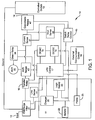
- FIG. 1 shows a block diagram of a line interactive uninterruptible power supply (UPS) 10 for providing AC power to a load.
- the UPS includes an input 12 to receive AC power from an AC power source, an output 14 that provides AC power to at least one controlled outlet 13, a DC voltage source 11 coupled to a DC to DC converter 15, an inverter 18 operatively coupled to the DC to DC converter 15 to receive DC power and to provide AC power, a transfer relay 16 selectively coupled to the UPS input 12 and the inverter 18, a UPS controller 17, an external communication control circuit 19 for communicating with external devices, an EMI/Surge filter 21, and an automatic voltage regulation (AVR) transformer 20 coupled to a bypass relay 34, the transfer relay 16 and at least one AVR relay 43.
- AVR automatic voltage regulation
- the DC voltage source 11 includes a battery 22, at least one backup battery pack 23, a battery charger 25 and a logic supply 35.
- the UPS controller 17 is coupled to a current sense circuit 37, a voltage sense circuit 39, a line sense circuit 41, a switch relay control 45 and at least one controllable relay 47.
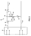
- the AVR transformer 20 includes an input 24, an output 30, a core 32 including a top portion 49, a middle portion 51 and a bottom portion 53, a first AVR relay 26 selectively coupled between the input 24 and either the top portion 49 of the core 32 or a first tap 27 coupled to the bottom portion 53 of the core 32, a second AVR relay 28 selectively coupled between the output 30 and either the top portion 49 of the core 32 or a second tap 29 coupled to the middle portion 51 of the core 32, and a bypass relay 34 for decoupling the AVR transformer core 32 from a neutral line 36.
- the first AVR relay 26, the second AVR relay 28 and the bypass relay 34 may be single pole double throw (SPDT) relays.
- the bypass relay 34 may also be a single pole single throw (SPST) relay.
- a metal oxide varistor may also be coupled across the bypass relay 34 to absorb energy when the bypass relay 34 is opened.
- the UPS controller 17 monitors the status of the UPS 10 by reading the outputs of the voltage sense circuit 39, the current sense circuit 37 and the line sense circuit 41. In monitoring the outputs, the UPS controller may determine whether the input voltage to the UPS 10 is in a normal or abnormal condition. The input voltage is in an abnormal condition if the input voltage at the input 12 of the UPS 10 is in a blackout, sag, or swell condition. Irrespective of the input voltage, the UPS controller 17 operates the UPS 10 and the AVR transformer 20 so that the voltage at the output 30 is within predetermined values, i.e. a nominal value plus or minus a given threshold.
- the UPS controller 17 activates the transfer relay 16 to couple the AVR transformer 20 to the inverter 18 to receive voltage from the DC voltage source 11 instead of the input 12.
- DC power from the DC voltage source 11 is regulated by the DC to DC converter 15, which is controlled by the UPS controller 17.
- the regulated DC power from the DC/DC converter 15 is converted to AC power by the inverter 18 and output to the transfer relay 16 and AVR transformer 20.
- FIG. 3 which shows operation in inverter mode, the UPS controller 17 adjusts the AVR relays 26,28 to an inverter mode in which the AVR transformer 20 is not required to perform an output voltage regulation function.
- the AVR transformer is not required to perform an output voltage regulation function because the DC voltage from the DC voltage source 11 is already regulated by the DC/DC converter 15 and DC/AC converter 18.
- the first AVR relay 26 is set in a second position 48 and the second AVR relay 28 is set in a second position 44 with both AVR relays 26, 28 coupled to the top portion 49 of the core 32 so that the taps 27, 29 are de-energized and the voltage at the output 30 of the AVR transformer 20 is equal to the voltage at the input 24 of the AVR transformer 20.
- the bypass relay 34 is opened to decouple the core 32 of the AVR transformer from a neutral line 36 to eliminate any potential losses due to the AVR transformer 20.
- the UPS controller also operates a set of controllable relays 47, through a switch relay control 45, which determine which controlled outlets 13 will be connected to the output 14.
- the transfer relay 16 couples the AVR transformer 20 to the input of the UPS 10 and the UPS controller 17 adjusts the AVR relays 26, 28 to a pass through mode in which the AVR transformer 20 is not required to perform an output voltage regulation function.
- the first AVR relay 26 is set in a second position 48 and the second AVR 28 is set in a second position 44 with AVR relays 26, 28 coupled to the top portion 49 of the core 32, so that the taps 27, 29 are de-energized and the voltage at the output 30 of the AVR transformer 20 is equal to the voltage at the input 24 of the AVR transformer 20.
- the bypass relay 34 is opened to decouple the core 32 of the AVR transformer from a neutral line 36 to eliminate any potential losses due to the AVR trans former 20.
- the transfer relay 16 couples the AVR transformer 20 to the input of the UPS 10 and the UPS controller 17 adjusts the AVR relays 26, 28, consequently activating or deactivating the corresponding taps 27, 29 to provide a stabilized voltage at the output 30 of the AVR transformer.
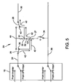
- the UPS controller 17 adjusts the AVR relays 26, 28 to a boost mode.
- the boost mode the first AVR relay 26 of the AVR transformer 20, is set in a first position 38, coupled to the bottom portion 53 of the core 32, so that the first tap 27 is energized and the second AVR relay 28 of the AVR transformer 20 is set in a first position 40, coupled to the middle portion 51 of the core 32, so that the second tap 29 is energized, allowing the electrical current 42 at the input 24 of the AVR transformer 20 to flow from the bottom portion 53 of the core 32 to the middle portion 51 of the core in a first direction, resulting in the voltage at the output 30 of the AVR transformer 20 being greater than the voltage at the input 24 of the AVR transformer 20.
- the increase of voltage between the output 30 and input 24 due to the AVR transformer 20 is directly correlated to the turn ratio of the core 32 of the AVR transformer 20 which varies depending on where the core 32 is tapped (determined by the first and second AVR relays 26, 28 and corresponding taps 27, 29 of the AVR transformer 20 ).
- the voltage at the output of the AVR transformer may be increased, in relation to the voltage at the input of the AVR transformer, by a first ratio.
- the first ratio may be 1:1.15.
- the second AVR relay 28 of the AVR transformer 20 can be put in a second position 44, coupled to the top portion 49 of the core 32, so that the second tap 29 is de-energized, allowing the current 46 to flow through a larger portion of the core 32, from the bottom portion 53 to the top portion 49, in the first direction, effectively increasing the turn ratio of the AVR transformer, and resulting in a larger voltage at the output 30.
- the voltage at the output of the AVR transformer may be increased by a second ratio which is greater than the first ratio.
- the second ratio may be double the value of the first ratio.
- the second ratio may be 1:1.3.
- the transfer relay 16 couples the AVR transformer 20 to the input of the UPS 10 and the UPS controller 17 adjusts the AVR relays 26, 28 to a trim mode.
- the first AVR relay 26 of the AVR transformer 20 is set in a second position 48, coupled to the top portion 49 of the core 32, so that the first tap 27 is de-energized
- the second AVR relay 28 of the AVR transformer 20 is set in a first position 40, coupled to the middle portion 51 of the core 32, so that the second tap 29 is energized, allowing the electrical current 50 at the input 24 of the AVR transformer 20 to flow through a section of the core 52 of the AVR transformer, from the top portion 49 to the middle portion 51, in a second direction, which results in the voltage at the output 30 of the AVR transformer 20 being lower than the voltage at the input 24 of the AVR transformer 20.
- the decrease of voltage between the output 30 and input 24 due to the AVR transformer 20 is directly correlated to the turn ratio of the core 32 of the AVR transformer 20.
- the voltage at the output of the AVR transformer may be decreased, in relation to the voltage at the input of the AVR transformer, by a ratio.
- the ratio may be 1.15:1.
- the UPS controller 17 engages the bypass relay as close to the zero crossing of the AC voltage waveform as possible to minimize any loss of volt-seconds. Additionally, in at least one embodiment the UPS controllers 17 engages the bypass relays and the AVR relays exactly 180 degree apart to minimize any loss of volt-seconds or imbalance.
- the bypass relay may be engaged first, followed by the AVR relays exactly one half cycle later.
- the AVR relays may be engaged first, followed by the bypass relay exactly one half cycle later.
- One advantage to at least one embodiment of the present invention described above is that the problems usually associated with AVR transformer energy loss in a UPS are reduced by de-energizing the core of the transformer and preventing losses due to the AVR transformer when the AVR is not performing a regulation function.
- de-energizing the core electric current is prevented from flowing in the core, which results in the elimination of any tare loss due to the AVR transformer when the ACR transformer is not performing a regulation function.
- Embodiments of the invention are described above in conjunction with a line interactive UPS.
- the methods and systems described herein can also be used with other types of uninterruptible power supplies and in a variety of power supply systems and voltage regulation systems.
- switches could be implemented in a variety of different ways such as, but not limited to, SPDT relays, SPST relays, transistors or other types of switches.
- the DC voltage supply 11 includes extra battery packs 23 to provide extra DC storage capacity, a battery charger for converting AC voltage from the input 12 into DC voltage to charge the battery 22 and backup battery packs 23, and a logic supply 35 for providing regulated DC voltages.
- other backup power sources may be used including AC and DC generators.
- the UPS controller 17 is connected to an external communication control circuit 19 to communicate with external devices.
- the input 12 is connected to an EMI/Surge filter 21 to provide EMI and surge protection to the UPS 10.
- controllable relays 47 are not included in the UPS and the controlled outlets 13 are not controlled outlets but are standard outlets.
- UPS controller could be implemented in a variety of different ways such as, but not limited to, a microprocessor, logic circuit, computer or other type of electronic controller.
Landscapes
- Business, Economics & Management (AREA)
- Emergency Management (AREA)
- Engineering & Computer Science (AREA)
- Power Engineering (AREA)
- Stand-By Power Supply Arrangements (AREA)
- Inverter Devices (AREA)
Claims (14)
- Un système d'alimentation en puissance sans interruption (UPS) (10) comprenant :une entrée (12) pour recevoir une puissance d'entrée ayant une tension d'entrée ;une sortie (14) pour fournir une puissance de sortie ;une ligne neutre (36) ;un transformateur de régulation de tension automatique (AVR) (20) couplé à l'entrée (12) et à la sortie (14) de l'UPS et ayant une entrée (24), une sortie (30), un noyau (32) et au moins un premier commutateur (26) et un deuxième commutateur (28), ledit premier commutateur (26) étant couplé de façon contrôlable au noyau (32) et à l'entrée (24) de transformateur AVR et ledit deuxième commutateur (28) étant couplé de façon contrôlable au noyau (32) et à la sortie (30) de transformateur AVR, caractérisé en ce que le système UPS (10) comprend en sus :un commutateur de dérivation (34) configuré pour coupler de façon sélective le noyau (32) du transformateur AVR à la ligne neutre (36) ; etun contrôleur (17) configuré pour contrôler le premier commutateur (26) et le deuxième commutateur (28) du transformateur AVR et le commutateur de dérivation (34), dans lequel le contrôleur (17) est configuré pour contrôler le commutateur de dérivation (34) afin d'isoler le noyau (32) du transformateur AVR de la ligne neutre (36) dans un premier mode de fonctionnement et de coupler le noyau (32) du transformateur AVR à la ligne neutre (36) dans un deuxième mode de fonctionnement ;dans lequel le contrôleur (17) est configuré pour, dans le premier mode de fonctionnement, coupler le premier commutateur (26) du transformateur AVR au noyau (32) et à l'entrée (24) de transformateur AVR et le deuxième commutateur (28) du transformateur AVR au noyau (32) et à la sortie (30) de transformateur AVR dans une configuration de fourniture d'une tension de sortie du transformateur AVR qui est égale à une tension d'entrée du transformateur AVR.
- Le système de la revendication 1, comprenant en sus une source de tension CC (11) et un onduleur (18) couplé à la source de tension CC (11), l'onduleur (18) étant couplé à l'entrée (24) du transformateur AVR et étant configuré pour fournir une puissance CA régulée au transformateur AVR (20).
- Le système de la revendication 2, dans lequel la source de tension CC (11) comporte une batterie (22).
- Le système de n'importe quelle revendication précédente, dans lequel le contrôleur (17) est configuré pour, dans le deuxième mode de fonctionnement, coupler le premier commutateur (26) du transformateur AVR au noyau (32) et à l'entrée (24) de transformateur AVR et le deuxième commutateur (28) du transformateur AVR au noyau (32) et à la sortie (30) de transformateur AVR dans une configuration de fourniture d'une tension de sortie du transformateur AVR qui est supérieure d'un premier coefficient à une tension d'entrée du transformateur AVR.
- Le système de la revendication 4, dans lequel le contrôleur (17) est configuré, dans un troisième mode de fonctionnement, pour contrôler le commutateur de dérivation (34) afin de coupler le noyau (32) du transformateur AVR à la ligne neutre (36) et dans lequel le contrôleur (17) est configuré en sus pour coupler le premier commutateur (26) du transformateur AVR au noyau (32) et à l'entrée (24) de transformateur AVR et le deuxième commutateur (28) du transformateur AVR au noyau (32) et à la sortie (30) de transformateur AVR dans une configuration de fourniture d'une tension de sortie du transformateur AVR qui est supérieure à la tension d'entrée du transformateur AVR d'un deuxième coefficient qui est plus grand que le premier coefficient.
- Le système de la revendication 5, dans lequel le deuxième coefficient est le double du premier coefficient.
- Le système de n'importe quelle revendication précédente, dans lequel le contrôleur (17) est configuré, dans un quatrième mode de fonctionnement, pour contrôler le commutateur de dérivation (34) afin de coupler le noyau (32) du transformateur AVR à la ligne neutre (36) et dans lequel le contrôleur (17) est configuré en sus pour coupler le premier commutateur (26) du transformateur AVR au noyau (32) et à l'entrée (24) de transformateur AVR et le deuxième commutateur (28) du transformateur AVR au noyau (32) et à la sortie (30) de transformateur AVR dans une configuration de fourniture d'une tension de sortie du transformateur AVR qui est inférieure à la tension d'entrée du transformateur AVR.
- Le système de n'importe quelle revendication précédente, dans lequel le commutateur de dérivation (34) est un commutateur électromagnétique.
- Le système de la revendication 8, dans lequel le commutateur électromagnétique est un relais.
- Une méthode pour fournir une puissance stable dans une alimentation en puissance sans interruption (UPS) (10) ayant un transformateur de régulation de tension automatique (AVR) (20), une entrée (12) pour recevoir une puissance d'entrée ayant une tension d'entrée avec une forme d'onde de tension CA, une sortie (14) pour fournir une puissance de sortie ayant une tension de sortie, et une ligne neutre (36), le transformateur AVR (20) ayant une entrée (24), une sortie (30), un noyau (32) et au moins un premier commutateur (26) et un deuxième commutateur (28), la méthode comprenant la détermination de savoir si la tension d'entrée dans l'UPS (10) est dans une tolérance spécifiée ; caractérisée en ce que ledit transformateur AVR (20) a ledit noyau (32) couplé de façon sélective à la ligne neutre (36), l'entrée (24) de transformateur AVR et la sortie (30) de transformateur AVR (30) et en ce que ladite méthode comprend en sus :si la tension d'entrée dans l'UPS (10) satisfait à une première condition, l'isolement du noyau (32) du transformateur AVR de la ligne neutre (36) et le couplage dudit premier commutateur (26) du transformateur AVR au noyau (32) et à l'entrée (24) de transformateur AVR et le couplage dudit deuxième commutateur (28) du transformateur AVR au noyau (32) et à la sortie (30) de transformateur AVR dans une configuration qui fournit une tension de sortie du transformateur AVR qui est égale à une tension d'entrée du transformateur AVR ; etsi la tension d'entrée de l'UPS satisfait à une deuxième condition, le couplage du noyau (32) du transformateur AVR à la ligne neutre (36).
- La méthode de la revendication 10, comprenant en outre les actions consistant :à configurer le transformateur AVR (20) pour augmenter la tension de sortie de l'UPS si la tension d'entrée de l'UPS est inférieure à une tolérance spécifiée ; età configurer le transformateur AVR (20) pour réduire la tension de sortie de l'UPS si la tension d'entrée de l'UPS est supérieure à une tolérance spécifiée.
- La méthode de la revendication 10, dans laquelle l'action d'isolement comprend une action consistant à découpler le noyau (32) du transformateur AVR de la ligne neutre (36).
- La méthode de la revendication 10, 11 ou 12, dans laquelle l'UPS (10) comporte un commutateur de dérivation (34) configuré pour coupler de façon sélective le noyau (32) du transformateur AVR à la ligne neutre (36),
dans laquelle l'action d'isolement comprend en sus une action consistant à coupler des premier et deuxième commutateurs (26, 28) au noyau (32) et un demi-cycle plus tard, à contrôler le commutateur de dérivation (34) pour découpler le noyau (32) de la ligne neutre (36),
dans laquelle l'action de couplage du noyau (32) à la ligne neutre (36) comprend en sus une action consistant à contrôler le commutateur de dérivation (34) afin de coupler le noyau (32) à la ligne neutre (36) et un demi-cycle plus tard, à coupler les premier et deuxième commutateurs (26, 28) au noyau (32). - La méthode de la revendication 13, dans laquelle l'action de contrôle du commutateur de dérivation (34) afin de découpler le noyau (32) de la ligne neutre (36) comprend une action consistant à exciter le commutateur de dérivation (34) à un passage à zéro de la forme d'onde de tension CA,
dans laquelle l'action de contrôle du commutateur de dérivation (34) afin de coupler le noyau (32) à la ligne neutre (36) comprend une action consistant à exciter le commutateur de dérivation (34) à un passage à zéro de la forme d'onde de tension CA.
Applications Claiming Priority (2)
| Application Number | Priority Date | Filing Date | Title |
|---|---|---|---|
| US12/360,648 US8212402B2 (en) | 2009-01-27 | 2009-01-27 | System and method for limiting losses in an uninterruptible power supply |
| PCT/US2009/064144 WO2010090666A1 (fr) | 2009-01-27 | 2009-11-12 | Système et procédé permettant de limiter les pertes dans une alimentation électrique ininterruptible |
Publications (2)
| Publication Number | Publication Date |
|---|---|
| EP2392065A1 EP2392065A1 (fr) | 2011-12-07 |
| EP2392065B1 true EP2392065B1 (fr) | 2016-06-01 |
Family
ID=42115773
Family Applications (1)
| Application Number | Title | Priority Date | Filing Date |
|---|---|---|---|
| EP09761079.4A Active EP2392065B1 (fr) | 2009-01-27 | 2009-11-12 | Système et procédé permettant de limiter les pertes dans une alimentation électrique ininterruptible |
Country Status (7)
| Country | Link |
|---|---|
| US (2) | US8212402B2 (fr) |
| EP (1) | EP2392065B1 (fr) |
| JP (1) | JP5602158B2 (fr) |
| CN (1) | CN102356532B (fr) |
| AU (1) | AU2009339281B2 (fr) |
| CA (1) | CA2750887C (fr) |
| WO (1) | WO2010090666A1 (fr) |
Families Citing this family (17)
| Publication number | Priority date | Publication date | Assignee | Title |
|---|---|---|---|---|
| WO2008138016A1 (fr) * | 2007-05-08 | 2008-11-13 | American Power Conversion Corporation | Gestion de l'énergie d'une source alternative |
| US8212402B2 (en) | 2009-01-27 | 2012-07-03 | American Power Conversion Corporation | System and method for limiting losses in an uninterruptible power supply |
| EP2810812B1 (fr) * | 2012-01-30 | 2019-08-21 | Mitsubishi Electric Corporation | Système de circuits principaux pour matériel roulant électrique |
| US9438036B2 (en) * | 2013-03-14 | 2016-09-06 | Cooper Technologies Company | Systems and methods for bypassing a voltage regulator |
| CN104882913A (zh) * | 2014-02-27 | 2015-09-02 | 伊顿制造(格拉斯哥)有限合伙莫尔日分支机构 | 一种ups电路 |
| US9735616B2 (en) | 2014-03-13 | 2017-08-15 | General Electric Company | Systems and methods for providing increased fault current capability in uninterruptible power supply systems |
| US10797490B2 (en) * | 2014-03-26 | 2020-10-06 | Intersil Americas LLC | Battery charge system with transition control that protects adapter components when transitioning from battery mode to adapter mode |
| JP7020803B2 (ja) * | 2017-06-12 | 2022-02-16 | 株式会社東芝 | 監視制御装置 |
| US10606291B2 (en) * | 2017-07-06 | 2020-03-31 | Cyber Power Systems Inc. | Power output control module for a power distributor |
| US10944287B2 (en) * | 2018-07-02 | 2021-03-09 | Schneider Electric It Corporation | AVR bypass relay welding detection |
| US11557979B2 (en) * | 2018-11-14 | 2023-01-17 | Eaton Intelligent Power Limited | Variable frequency drive with integrated front-end rectifier and bypass |
| CN109818414B (zh) * | 2019-03-15 | 2024-08-23 | 谢志和 | 一种交直流转换的电源系统 |
| CN110061559B (zh) * | 2019-05-24 | 2022-01-25 | 联正电子(深圳)有限公司 | 离线式不间断电源及其控制方法 |
| US11243264B2 (en) | 2020-04-22 | 2022-02-08 | Renesas Electronics Corporation | Abnormal power supply voltage detection device and method for detecting abnormal power supply voltage |
| CN111917174B (zh) * | 2020-08-27 | 2023-05-02 | 东莞市硕擎能源科技有限公司 | Ups电源及其电压调节装置 |
| CN112701781A (zh) * | 2021-01-26 | 2021-04-23 | 东莞市硕擎能源科技有限公司 | Ups的节能电源电路 |
| US20240047986A1 (en) * | 2022-08-04 | 2024-02-08 | Intel Corporation | Electrical decoupling power delivery resources to improve efficiency of a low power state |
Citations (3)
| Publication number | Priority date | Publication date | Assignee | Title |
|---|---|---|---|---|
| JPS5710023U (fr) * | 1980-06-19 | 1982-01-19 | ||
| JP2000293242A (ja) * | 1999-04-05 | 2000-10-20 | Kawamura Electric Inc | 電圧制御装置 |
| US6348782B1 (en) * | 1998-10-02 | 2002-02-19 | Powerware Corporation | Uninterruptible power supply systems, voltage regulators and operating methods employing controlled ferroresonant transformer circuits |
Family Cites Families (38)
| Publication number | Priority date | Publication date | Assignee | Title |
|---|---|---|---|---|
| US4564767A (en) | 1983-11-07 | 1986-01-14 | Tii Industries, Inc. | Uninterruptible switching power supply system |
| US4673825A (en) | 1985-02-15 | 1987-06-16 | Exide Electronics Corporation | Uninterruptible power supply with isolated bypass winding |
| US4745352A (en) * | 1987-06-08 | 1988-05-17 | Topaz, Inc. | Switching AC voltage regulator |
| US4763013A (en) | 1987-09-21 | 1988-08-09 | American Telephone And Telegraph Company, At&T Bell Laboratories | Backup protection switch to prevent reverse power flow in a UPS |
| US4916329A (en) * | 1987-10-05 | 1990-04-10 | Square D Company | Uninterruptible power supply |
| US4831508A (en) | 1987-10-20 | 1989-05-16 | Computer Products Inc. | Power supply system having improved input power factor |
| US4791348A (en) * | 1988-01-06 | 1988-12-13 | Square D Company | Switching ac voltage regulator |
| JPH02146939A (ja) * | 1988-11-24 | 1990-06-06 | Nippon Electric Ind Co Ltd | 高効率交流無停電電源装置 |
| US4903186A (en) | 1989-05-22 | 1990-02-20 | Pullen Jr Keats A | Transformer-rectifier with ripple filter |
| US5075617A (en) * | 1990-05-02 | 1991-12-24 | Abex Corporation | Automatic line drop compensator |
| US5181170A (en) * | 1991-12-26 | 1993-01-19 | Wisconsin Alumni Research Foundation | High efficiency DC/DC current source converter |
| US6274950B1 (en) | 1994-03-03 | 2001-08-14 | American Power Conversion | Battery communication system |
| US5751564A (en) | 1994-08-10 | 1998-05-12 | Dien; Ghing-Hsin | Dual/multiple voltage level input switching power supply |
| US5579197A (en) | 1995-01-24 | 1996-11-26 | Best Power Technology, Incorporated | Backup power system and method |
| US5602462A (en) * | 1995-02-21 | 1997-02-11 | Best Power Technology, Incorporated | Uninterruptible power system |
| US5793625A (en) * | 1997-01-24 | 1998-08-11 | Baker Hughes Incorporated | Boost converter regulated alternator |
| JP2000116005A (ja) * | 1998-10-02 | 2000-04-21 | Sanken Electric Co Ltd | 交流電源装置 |
| JP2000172350A (ja) * | 1998-12-08 | 2000-06-23 | Hitachi Ltd | 無停電電源装置及びその制御方法 |
| WO2000057341A2 (fr) | 1999-03-22 | 2000-09-28 | Escript, Inc. | Procede et appareil de traitement, mise a jour, et gestion d'une requete d'un groupe medical d'accompagnement |
| US6404658B1 (en) | 1999-05-13 | 2002-06-11 | American Power Conversion | Method and apparatus for converting a DC voltage to an AC voltage |
| US6160722A (en) * | 1999-08-13 | 2000-12-12 | Powerware Corporation | Uninterruptible power supplies with dual-sourcing capability and methods of operation thereof |
| US6356467B1 (en) * | 1999-10-01 | 2002-03-12 | Metropolitan Industries, Inc. | DC/DC boost converter with bypass circuitry |
| US6137277A (en) * | 1999-10-29 | 2000-10-24 | Inverpower Controls Ltd. | Static voltage regulator |
| JP2002064980A (ja) | 2000-08-16 | 2002-02-28 | Sony Corp | スイッチング電源回路 |
| US6353547B1 (en) | 2000-08-31 | 2002-03-05 | Delta Electronics, Inc. | Three-level soft-switched converters |
| CN2454974Y (zh) * | 2000-11-02 | 2001-10-17 | 系统电子工业股份有限公司 | 自动调整不间断电源的侦测装置 |
| US6429629B1 (en) * | 2001-03-08 | 2002-08-06 | Tranh To Nguyen | Switch-mode power supplies |
| US7141892B2 (en) | 2002-08-20 | 2006-11-28 | Phoenixtec Power Co., Ltd. | Power supply method of a line interactive UPS and the line interactive UPS |
| CN1327590C (zh) * | 2003-06-05 | 2007-07-18 | 中兴通讯股份有限公司 | 一种用于实现不间断电源系统切换控制的静态开关装置 |
| TWI222778B (en) | 2003-07-30 | 2004-10-21 | Delta Electronics Inc | Lose-less voltage-clamping circuit |
| US7928665B2 (en) * | 2004-02-27 | 2011-04-19 | Honeywell International Inc. | System and methods for dimming a high pressure arc lamp |
| US20060146464A1 (en) | 2005-01-04 | 2006-07-06 | Fiskars Brands, Inc. | Overvoltage protection device |
| TWM292203U (en) | 2005-12-26 | 2006-06-11 | Cyber Power Systems Inc | Automatic voltage-stabilizing circuit for uninterruptible power supply (UPS) |
| KR100908783B1 (ko) * | 2007-07-25 | 2009-07-22 | 한국전력공사 | 무정전 기능이 구비된 스위칭 장치 및 이를 이용한 변압기권수비 조절 방법 및 변압기 전압 조절 방법 |
| US7911085B2 (en) | 2008-01-15 | 2011-03-22 | Cyber Power System Inc. | Power saving uninterruptible power supply |
| US20090179496A1 (en) | 2008-01-15 | 2009-07-16 | Cyber Power System Inc. | Power saving uninterruptible power supply |
| US8102678B2 (en) * | 2008-05-21 | 2012-01-24 | Flextronics Ap, Llc | High power factor isolated buck-type power factor correction converter |
| US8212402B2 (en) | 2009-01-27 | 2012-07-03 | American Power Conversion Corporation | System and method for limiting losses in an uninterruptible power supply |
-
2009
- 2009-01-27 US US12/360,648 patent/US8212402B2/en active Active
- 2009-11-12 AU AU2009339281A patent/AU2009339281B2/en not_active Ceased
- 2009-11-12 JP JP2011547921A patent/JP5602158B2/ja active Active
- 2009-11-12 WO PCT/US2009/064144 patent/WO2010090666A1/fr not_active Ceased
- 2009-11-12 EP EP09761079.4A patent/EP2392065B1/fr active Active
- 2009-11-12 CA CA2750887A patent/CA2750887C/fr not_active Expired - Fee Related
- 2009-11-12 CN CN200980158124.XA patent/CN102356532B/zh active Active
-
2012
- 2012-07-02 US US13/539,924 patent/US8450876B2/en active Active
Patent Citations (3)
| Publication number | Priority date | Publication date | Assignee | Title |
|---|---|---|---|---|
| JPS5710023U (fr) * | 1980-06-19 | 1982-01-19 | ||
| US6348782B1 (en) * | 1998-10-02 | 2002-02-19 | Powerware Corporation | Uninterruptible power supply systems, voltage regulators and operating methods employing controlled ferroresonant transformer circuits |
| JP2000293242A (ja) * | 1999-04-05 | 2000-10-20 | Kawamura Electric Inc | 電圧制御装置 |
Also Published As
| Publication number | Publication date |
|---|---|
| US8450876B2 (en) | 2013-05-28 |
| JP2012516674A (ja) | 2012-07-19 |
| EP2392065A1 (fr) | 2011-12-07 |
| US8212402B2 (en) | 2012-07-03 |
| CN102356532A (zh) | 2012-02-15 |
| JP5602158B2 (ja) | 2014-10-08 |
| US20130002029A1 (en) | 2013-01-03 |
| CA2750887A1 (fr) | 2010-08-12 |
| CA2750887C (fr) | 2016-07-19 |
| AU2009339281B2 (en) | 2015-10-29 |
| CN102356532B (zh) | 2014-07-16 |
| US20100188066A1 (en) | 2010-07-29 |
| AU2009339281A1 (en) | 2011-08-18 |
| WO2010090666A1 (fr) | 2010-08-12 |
Similar Documents
| Publication | Publication Date | Title |
|---|---|---|
| EP2392065B1 (fr) | Système et procédé permettant de limiter les pertes dans une alimentation électrique ininterruptible | |
| EP3190682B1 (fr) | Système et procédé d'alimentation électrique | |
| EP2966740B1 (fr) | Système d'alimentation en courant continu pour des applications maritimes | |
| EP2759038B1 (fr) | Systèmes et procédés d'alimentation sans coupure employant un stockage d'énergie à la demande | |
| US7456520B2 (en) | Control system, method and product for uninterruptible power supply | |
| US8422256B2 (en) | Control system for high-efficiency operation in parallel inverter installations | |
| EP2820751B1 (fr) | Ups dotée d'un convertisseur en triangle employé comme régulateur de puissance d'entrée dans un système à double conversion | |
| WO2002021659A1 (fr) | Conditionneur de puissance a haute efficacite pour des cellules electrochimiques | |
| CN109286320A (zh) | 电压转换单元 | |
| JP2013070551A (ja) | マルチ出力無停電電源装置 | |
| EP2278686B1 (fr) | Methode et dispositif d'alimentation sans interruption | |
| EP1294073B1 (fr) | Module d'alimentation de secours pour commander et surveiller le réseau industriellement | |
| EP2999078B1 (fr) | Système d'alimentation électrique sans interruption cc et ca et procédé de commande de ce dernier | |
| CN115940302A (zh) | 持久dc断路器 | |
| HK1165108B (en) | System and method for limiting losses in an uninterruptible power supply | |
| EP3651306A1 (fr) | Système d'alimentation intrinsèque pour services auxiliaires de convertisseurs de puissance | |
| RU2414788C1 (ru) | Многоканальный агрегат бесперебойного питания модульной конструкции | |
| EP1311049B1 (fr) | Procéde et reseau pour fournir puissance de secours à des dispositifs en reseau | |
| JP2000139040A (ja) | 無停電電源装置 | |
| Al Dubaikel et al. | Comparison between transformer-based Vs. transformer-less UPS systems | |
| CN119765612A (zh) | 一种安全供电回路及其控制方法 | |
| CN119927893A (zh) | 一种机器人及其供电控制系统 | |
| Murdoch et al. | A Modular 200Amp-48Volt off Line Switch Mode Rectifier |
Legal Events
| Date | Code | Title | Description |
|---|---|---|---|
| PUAI | Public reference made under article 153(3) epc to a published international application that has entered the european phase |
Free format text: ORIGINAL CODE: 0009012 |
|
| 17P | Request for examination filed |
Effective date: 20110825 |
|
| AK | Designated contracting states |
Kind code of ref document: A1 Designated state(s): AT BE BG CH CY CZ DE DK EE ES FI FR GB GR HR HU IE IS IT LI LT LU LV MC MK MT NL NO PL PT RO SE SI SK SM TR |
|
| RIN1 | Information on inventor provided before grant (corrected) |
Inventor name: PAIK, NAMWOOK Inventor name: SHENG-HSIEN, FANG Inventor name: RODENHISER, FRED, WILLIAM Inventor name: DEOKAR, VISHWAS, MOHANIRAJ |
|
| DAX | Request for extension of the european patent (deleted) | ||
| REG | Reference to a national code |
Ref country code: HK Ref legal event code: DE Ref document number: 1165108 Country of ref document: HK |
|
| 17Q | First examination report despatched |
Effective date: 20150528 |
|
| RIC1 | Information provided on ipc code assigned before grant |
Ipc: H02J 9/00 20060101ALI20150930BHEP Ipc: H02J 9/06 20060101AFI20150930BHEP |
|
| GRAP | Despatch of communication of intention to grant a patent |
Free format text: ORIGINAL CODE: EPIDOSNIGR1 |
|
| INTG | Intention to grant announced |
Effective date: 20160108 |
|
| GRAR | Information related to intention to grant a patent recorded |
Free format text: ORIGINAL CODE: EPIDOSNIGR71 |
|
| GRAS | Grant fee paid |
Free format text: ORIGINAL CODE: EPIDOSNIGR3 |
|
| GRAA | (expected) grant |
Free format text: ORIGINAL CODE: 0009210 |
|
| RAP1 | Party data changed (applicant data changed or rights of an application transferred) |
Owner name: SCHNEIDER ELECTRIC IT CORPORATION |
|
| INTG | Intention to grant announced |
Effective date: 20160419 |
|
| AK | Designated contracting states |
Kind code of ref document: B1 Designated state(s): AT BE BG CH CY CZ DE DK EE ES FI FR GB GR HR HU IE IS IT LI LT LU LV MC MK MT NL NO PL PT RO SE SI SK SM TR |
|
| REG | Reference to a national code |
Ref country code: GB Ref legal event code: FG4D |
|
| REG | Reference to a national code |
Ref country code: CH Ref legal event code: EP Ref country code: AT Ref legal event code: REF Ref document number: 804408 Country of ref document: AT Kind code of ref document: T Effective date: 20160615 |
|
| REG | Reference to a national code |
Ref country code: IE Ref legal event code: FG4D |
|
| REG | Reference to a national code |
Ref country code: DE Ref legal event code: R096 Ref document number: 602009039025 Country of ref document: DE |
|
| REG | Reference to a national code |
Ref country code: LT Ref legal event code: MG4D |
|
| REG | Reference to a national code |
Ref country code: NL Ref legal event code: MP Effective date: 20160601 |
|
| PG25 | Lapsed in a contracting state [announced via postgrant information from national office to epo] |
Ref country code: FI Free format text: LAPSE BECAUSE OF FAILURE TO SUBMIT A TRANSLATION OF THE DESCRIPTION OR TO PAY THE FEE WITHIN THE PRESCRIBED TIME-LIMIT Effective date: 20160601 Ref country code: LT Free format text: LAPSE BECAUSE OF FAILURE TO SUBMIT A TRANSLATION OF THE DESCRIPTION OR TO PAY THE FEE WITHIN THE PRESCRIBED TIME-LIMIT Effective date: 20160601 Ref country code: NO Free format text: LAPSE BECAUSE OF FAILURE TO SUBMIT A TRANSLATION OF THE DESCRIPTION OR TO PAY THE FEE WITHIN THE PRESCRIBED TIME-LIMIT Effective date: 20160901 |
|
| REG | Reference to a national code |
Ref country code: AT Ref legal event code: MK05 Ref document number: 804408 Country of ref document: AT Kind code of ref document: T Effective date: 20160601 |
|
| REG | Reference to a national code |
Ref country code: FR Ref legal event code: PLFP Year of fee payment: 8 |
|
| PG25 | Lapsed in a contracting state [announced via postgrant information from national office to epo] |
Ref country code: ES Free format text: LAPSE BECAUSE OF FAILURE TO SUBMIT A TRANSLATION OF THE DESCRIPTION OR TO PAY THE FEE WITHIN THE PRESCRIBED TIME-LIMIT Effective date: 20160601 Ref country code: HR Free format text: LAPSE BECAUSE OF FAILURE TO SUBMIT A TRANSLATION OF THE DESCRIPTION OR TO PAY THE FEE WITHIN THE PRESCRIBED TIME-LIMIT Effective date: 20160601 Ref country code: NL Free format text: LAPSE BECAUSE OF FAILURE TO SUBMIT A TRANSLATION OF THE DESCRIPTION OR TO PAY THE FEE WITHIN THE PRESCRIBED TIME-LIMIT Effective date: 20160601 Ref country code: LV Free format text: LAPSE BECAUSE OF FAILURE TO SUBMIT A TRANSLATION OF THE DESCRIPTION OR TO PAY THE FEE WITHIN THE PRESCRIBED TIME-LIMIT Effective date: 20160601 Ref country code: SE Free format text: LAPSE BECAUSE OF FAILURE TO SUBMIT A TRANSLATION OF THE DESCRIPTION OR TO PAY THE FEE WITHIN THE PRESCRIBED TIME-LIMIT Effective date: 20160601 Ref country code: GR Free format text: LAPSE BECAUSE OF FAILURE TO SUBMIT A TRANSLATION OF THE DESCRIPTION OR TO PAY THE FEE WITHIN THE PRESCRIBED TIME-LIMIT Effective date: 20160902 |
|
| PG25 | Lapsed in a contracting state [announced via postgrant information from national office to epo] |
Ref country code: IS Free format text: LAPSE BECAUSE OF FAILURE TO SUBMIT A TRANSLATION OF THE DESCRIPTION OR TO PAY THE FEE WITHIN THE PRESCRIBED TIME-LIMIT Effective date: 20161001 Ref country code: IT Free format text: LAPSE BECAUSE OF FAILURE TO SUBMIT A TRANSLATION OF THE DESCRIPTION OR TO PAY THE FEE WITHIN THE PRESCRIBED TIME-LIMIT Effective date: 20160601 Ref country code: RO Free format text: LAPSE BECAUSE OF FAILURE TO SUBMIT A TRANSLATION OF THE DESCRIPTION OR TO PAY THE FEE WITHIN THE PRESCRIBED TIME-LIMIT Effective date: 20160601 Ref country code: SK Free format text: LAPSE BECAUSE OF FAILURE TO SUBMIT A TRANSLATION OF THE DESCRIPTION OR TO PAY THE FEE WITHIN THE PRESCRIBED TIME-LIMIT Effective date: 20160601 Ref country code: CZ Free format text: LAPSE BECAUSE OF FAILURE TO SUBMIT A TRANSLATION OF THE DESCRIPTION OR TO PAY THE FEE WITHIN THE PRESCRIBED TIME-LIMIT Effective date: 20160601 Ref country code: EE Free format text: LAPSE BECAUSE OF FAILURE TO SUBMIT A TRANSLATION OF THE DESCRIPTION OR TO PAY THE FEE WITHIN THE PRESCRIBED TIME-LIMIT Effective date: 20160601 |
|
| PG25 | Lapsed in a contracting state [announced via postgrant information from national office to epo] |
Ref country code: PT Free format text: LAPSE BECAUSE OF FAILURE TO SUBMIT A TRANSLATION OF THE DESCRIPTION OR TO PAY THE FEE WITHIN THE PRESCRIBED TIME-LIMIT Effective date: 20161003 Ref country code: SM Free format text: LAPSE BECAUSE OF FAILURE TO SUBMIT A TRANSLATION OF THE DESCRIPTION OR TO PAY THE FEE WITHIN THE PRESCRIBED TIME-LIMIT Effective date: 20160601 Ref country code: BE Free format text: LAPSE BECAUSE OF FAILURE TO SUBMIT A TRANSLATION OF THE DESCRIPTION OR TO PAY THE FEE WITHIN THE PRESCRIBED TIME-LIMIT Effective date: 20160601 Ref country code: PL Free format text: LAPSE BECAUSE OF FAILURE TO SUBMIT A TRANSLATION OF THE DESCRIPTION OR TO PAY THE FEE WITHIN THE PRESCRIBED TIME-LIMIT Effective date: 20160601 Ref country code: AT Free format text: LAPSE BECAUSE OF FAILURE TO SUBMIT A TRANSLATION OF THE DESCRIPTION OR TO PAY THE FEE WITHIN THE PRESCRIBED TIME-LIMIT Effective date: 20160601 |
|
| REG | Reference to a national code |
Ref country code: DE Ref legal event code: R097 Ref document number: 602009039025 Country of ref document: DE |
|
| PLBE | No opposition filed within time limit |
Free format text: ORIGINAL CODE: 0009261 |
|
| STAA | Information on the status of an ep patent application or granted ep patent |
Free format text: STATUS: NO OPPOSITION FILED WITHIN TIME LIMIT |
|
| 26N | No opposition filed |
Effective date: 20170302 |
|
| PG25 | Lapsed in a contracting state [announced via postgrant information from national office to epo] |
Ref country code: DK Free format text: LAPSE BECAUSE OF FAILURE TO SUBMIT A TRANSLATION OF THE DESCRIPTION OR TO PAY THE FEE WITHIN THE PRESCRIBED TIME-LIMIT Effective date: 20160601 Ref country code: SI Free format text: LAPSE BECAUSE OF FAILURE TO SUBMIT A TRANSLATION OF THE DESCRIPTION OR TO PAY THE FEE WITHIN THE PRESCRIBED TIME-LIMIT Effective date: 20160601 |
|
| REG | Reference to a national code |
Ref country code: CH Ref legal event code: PL |
|
| PG25 | Lapsed in a contracting state [announced via postgrant information from national office to epo] |
Ref country code: LI Free format text: LAPSE BECAUSE OF NON-PAYMENT OF DUE FEES Effective date: 20161130 Ref country code: CH Free format text: LAPSE BECAUSE OF NON-PAYMENT OF DUE FEES Effective date: 20161130 |
|
| REG | Reference to a national code |
Ref country code: IE Ref legal event code: MM4A |
|
| REG | Reference to a national code |
Ref country code: HK Ref legal event code: GR Ref document number: 1165108 Country of ref document: HK |
|
| PG25 | Lapsed in a contracting state [announced via postgrant information from national office to epo] |
Ref country code: LU Free format text: LAPSE BECAUSE OF NON-PAYMENT OF DUE FEES Effective date: 20161130 |
|
| REG | Reference to a national code |
Ref country code: FR Ref legal event code: PLFP Year of fee payment: 9 |
|
| PG25 | Lapsed in a contracting state [announced via postgrant information from national office to epo] |
Ref country code: IE Free format text: LAPSE BECAUSE OF NON-PAYMENT OF DUE FEES Effective date: 20161112 |
|
| PG25 | Lapsed in a contracting state [announced via postgrant information from national office to epo] |
Ref country code: HU Free format text: LAPSE BECAUSE OF FAILURE TO SUBMIT A TRANSLATION OF THE DESCRIPTION OR TO PAY THE FEE WITHIN THE PRESCRIBED TIME-LIMIT; INVALID AB INITIO Effective date: 20091112 Ref country code: CY Free format text: LAPSE BECAUSE OF FAILURE TO SUBMIT A TRANSLATION OF THE DESCRIPTION OR TO PAY THE FEE WITHIN THE PRESCRIBED TIME-LIMIT Effective date: 20160601 |
|
| PG25 | Lapsed in a contracting state [announced via postgrant information from national office to epo] |
Ref country code: MK Free format text: LAPSE BECAUSE OF FAILURE TO SUBMIT A TRANSLATION OF THE DESCRIPTION OR TO PAY THE FEE WITHIN THE PRESCRIBED TIME-LIMIT Effective date: 20160601 Ref country code: MC Free format text: LAPSE BECAUSE OF FAILURE TO SUBMIT A TRANSLATION OF THE DESCRIPTION OR TO PAY THE FEE WITHIN THE PRESCRIBED TIME-LIMIT Effective date: 20160601 Ref country code: TR Free format text: LAPSE BECAUSE OF FAILURE TO SUBMIT A TRANSLATION OF THE DESCRIPTION OR TO PAY THE FEE WITHIN THE PRESCRIBED TIME-LIMIT Effective date: 20160601 |
|
| PG25 | Lapsed in a contracting state [announced via postgrant information from national office to epo] |
Ref country code: BG Free format text: LAPSE BECAUSE OF FAILURE TO SUBMIT A TRANSLATION OF THE DESCRIPTION OR TO PAY THE FEE WITHIN THE PRESCRIBED TIME-LIMIT Effective date: 20160601 |
|
| PG25 | Lapsed in a contracting state [announced via postgrant information from national office to epo] |
Ref country code: MT Free format text: LAPSE BECAUSE OF NON-PAYMENT OF DUE FEES Effective date: 20161112 |
|
| PGFP | Annual fee paid to national office [announced via postgrant information from national office to epo] |
Ref country code: DE Payment date: 20241128 Year of fee payment: 16 |
|
| PGFP | Annual fee paid to national office [announced via postgrant information from national office to epo] |
Ref country code: GB Payment date: 20241126 Year of fee payment: 16 |
|
| PGFP | Annual fee paid to national office [announced via postgrant information from national office to epo] |
Ref country code: FR Payment date: 20241126 Year of fee payment: 16 |