EP2392435A2 - Système de manipulation d'outil et procédé de manipulation de pièces usinées à l'aide de manipulateurs coopérants - Google Patents
Système de manipulation d'outil et procédé de manipulation de pièces usinées à l'aide de manipulateurs coopérants Download PDFInfo
- Publication number
- EP2392435A2 EP2392435A2 EP11168345A EP11168345A EP2392435A2 EP 2392435 A2 EP2392435 A2 EP 2392435A2 EP 11168345 A EP11168345 A EP 11168345A EP 11168345 A EP11168345 A EP 11168345A EP 2392435 A2 EP2392435 A2 EP 2392435A2
- Authority
- EP
- European Patent Office
- Prior art keywords
- manipulator
- workpiece
- manipulators
- control device
- handling system
- Prior art date
- Legal status (The legal status is an assumption and is not a legal conclusion. Google has not performed a legal analysis and makes no representation as to the accuracy of the status listed.)
- Granted
Links
Images

Classifications
-
- B—PERFORMING OPERATIONS; TRANSPORTING
- B25—HAND TOOLS; PORTABLE POWER-DRIVEN TOOLS; MANIPULATORS
- B25J—MANIPULATORS; CHAMBERS PROVIDED WITH MANIPULATION DEVICES
- B25J9/00—Program-controlled manipulators
- B25J9/16—Program controls
- B25J9/1679—Program controls characterised by the tasks executed
- B25J9/1682—Dual arm manipulator; Coordination of several manipulators
-
- B—PERFORMING OPERATIONS; TRANSPORTING
- B25—HAND TOOLS; PORTABLE POWER-DRIVEN TOOLS; MANIPULATORS
- B25J—MANIPULATORS; CHAMBERS PROVIDED WITH MANIPULATION DEVICES
- B25J9/00—Program-controlled manipulators
- B25J9/16—Program controls
- B25J9/1656—Program controls characterised by programming, planning systems for manipulators
-
- G—PHYSICS
- G05—CONTROLLING; REGULATING
- G05B—CONTROL OR REGULATING SYSTEMS IN GENERAL; FUNCTIONAL ELEMENTS OF SUCH SYSTEMS; MONITORING OR TESTING ARRANGEMENTS FOR SUCH SYSTEMS OR ELEMENTS
- G05B19/00—Program-control systems
- G05B19/02—Program-control systems electric
- G05B19/42—Recording and playback systems, i.e. in which the program is recorded from a cycle of operations, e.g. the cycle of operations being manually controlled, after which this record is played back on the same machine
- G05B19/423—Teaching successive positions by walk-through, i.e. the tool head or end effector being grasped and guided directly, with or without servo-assistance, to follow a path
-
- G—PHYSICS
- G05—CONTROLLING; REGULATING
- G05B—CONTROL OR REGULATING SYSTEMS IN GENERAL; FUNCTIONAL ELEMENTS OF SUCH SYSTEMS; MONITORING OR TESTING ARRANGEMENTS FOR SUCH SYSTEMS OR ELEMENTS
- G05B2219/00—Program-control systems
- G05B2219/30—Nc systems
- G05B2219/36—Nc in input of data, input key till input tape
- G05B2219/36432—By putting some constraints on some DOF, move within limited volumes, areas, planes, limits motion in x, y or z planes, virtual reality constraints
-
- G—PHYSICS
- G05—CONTROLLING; REGULATING
- G05B—CONTROL OR REGULATING SYSTEMS IN GENERAL; FUNCTIONAL ELEMENTS OF SUCH SYSTEMS; MONITORING OR TESTING ARRANGEMENTS FOR SUCH SYSTEMS OR ELEMENTS
- G05B2219/00—Program-control systems
- G05B2219/30—Nc systems
- G05B2219/36—Nc in input of data, input key till input tape
- G05B2219/36433—Position assisted teaching
-
- G—PHYSICS
- G05—CONTROLLING; REGULATING
- G05B—CONTROL OR REGULATING SYSTEMS IN GENERAL; FUNCTIONAL ELEMENTS OF SUCH SYSTEMS; MONITORING OR TESTING ARRANGEMENTS FOR SUCH SYSTEMS OR ELEMENTS
- G05B2219/00—Program-control systems
- G05B2219/30—Nc systems
- G05B2219/39—Robotics, robotics to robotics hand
- G05B2219/39121—Two manipulators operate on same object
-
- G—PHYSICS
- G05—CONTROLLING; REGULATING
- G05B—CONTROL OR REGULATING SYSTEMS IN GENERAL; FUNCTIONAL ELEMENTS OF SUCH SYSTEMS; MONITORING OR TESTING ARRANGEMENTS FOR SUCH SYSTEMS OR ELEMENTS
- G05B2219/00—Program-control systems
- G05B2219/30—Nc systems
- G05B2219/39—Robotics, robotics to robotics hand
- G05B2219/39122—Follower, follower mirrors leader, leader
-
- G—PHYSICS
- G05—CONTROLLING; REGULATING
- G05B—CONTROL OR REGULATING SYSTEMS IN GENERAL; FUNCTIONAL ELEMENTS OF SUCH SYSTEMS; MONITORING OR TESTING ARRANGEMENTS FOR SUCH SYSTEMS OR ELEMENTS
- G05B2219/00—Program-control systems
- G05B2219/30—Nc systems
- G05B2219/39—Robotics, robotics to robotics hand
- G05B2219/39124—Grasp common rigid object, no movement end effectors relative to object
Definitions
- the invention relates to a workpiece handling system, comprising at least two manipulators cooperating for handling workpieces, which are automatically controllable and / or programmable by means of at least one freely programmable control device in three or more axes.
- the invention also relates to a method for manipulating workpieces by means of cooperating manipulators, which are controlled by at least one control device, in particular by means of a workpiece handling system according to the invention.
- a method for controlling a plurality of handling devices with a number of control units that are assigned to the handling devices such that each control unit controls at least one handling device, wherein an operating device accesses a plurality of control units for controlling the handling devices.
- the operating device is used for manual operation of handling devices such as industrial robots, for example in the context of learning processes (teaching), or for changing software-based control programs on the handling devices associated control units.
- the operating device usually has operating and input elements such as control levers or buttons and, where appropriate, display elements and are connected via cable or wireless communication with a robot control unit.
- the object of the invention is to provide a workpiece handling system and to provide a method which allows an intuitive handling of workpieces by cooperating manipulators.
- a workpiece handling system comprising at least two manipulators cooperating for handling workpieces, which are automatically controllable and / or programmable by means of at least one freely programmable control device in three or more axes, wherein at least one first manipulator in at least one of his Degree of freedom is set up for manually guided movement, and the control device is set up to automatically control at least one second manipulator in dependence on the manually guided manipulator.
- the workpiece handling system can be used for positioning or transporting, for example, heavy workpieces, alternatively or additionally to the assembly and / or machining of the workpiece.
- a plurality of workpieces can also be machined or handled simultaneously by the at least two cooperating manipulators, in particular in each case a workpiece can be processed or handled by a respective manipulator. wherein several workpieces can also be edited or handled by a manipulator in synchronized movements.
- the cooperating manipulators are part of a common handling system, so that the cooperating manipulators can also share a common workspace.
- each manipulator can be connected to a separate control device.
- the plurality of control devices may, for example, be connected and / or synchronized by means of interfaces and data lines.
- the cooperating manipulators can alternatively also be operated by a common control device.
- the common control device In addition, the plurality of separate control devices can additionally be monitored by a higher-level or secondary control device or coordinated with one another for co-operating cooperation.
- the first manipulator can be used in all degrees of freedom, i. for example, Cartesian in the three spatial directions and three rotations or, for example, axially related to his joints are moved manually guided.
- the first manipulator can be moved manually in less degrees of freedom, for example also only a single degree of freedom, for example in a Cartesian spatial direction or a spatial rotation or with respect to a joint.
- the second manipulator which is automatically controlled as a function of the manually guided manipulator, can simply copy the movement of the manually guided manipulator, ie perform the same movement synchronously.
- the automatically controlled manipulator synchronously perform a non-congruent in the geometrical sense ie similar movement.
- the automatically controlled manipulator may move the manually guided manipulator under another Copy the scale.
- the movement of the automatically controlled manipulator can be carried out later depending on the application instead of synchronously ie at the same time.
- the control device can be set up to operate the manually guided manipulator in at least one of its degrees of freedom and / or torque-controlled and to automatically control another manipulator as a function of the force- and / or torque-controlled manipulator.
- the manually guided manipulator will not be purely passive in this case. de-energized pushed by a user. Instead, in force and / or torque-controlled operation, a force applied by the user to the manipulator can form a controlled variable for automatically controlling or regulating the position of the manually guided manipulator. Haptic feedback can also be returned to the guided manipulator. The force that the user feels can be determined depending on the process status.
- the control device can be set up to operate one of the manipulators in at least one of its degrees of freedom by means of compliance control and to automatically control another manipulator as a function of the compliance-controlled manipulator.
- a compliance, i. Compliance control of the manipulator can be achieved in particular by means of an impedance control or an admittance control.
- the control device may be configured to generate the compliance of the manipulator by means of impedance regulation.
- An impedance control is based on an existing torque control at the joint level, in contrast to the admittance control.
- the deviation of the actual position from a defined desired position is measured, and a desired generalized force or forces and moments are determined according to the desired dynamic behavior.
- This force can be mapped via the known kinematics of the manipulator to corresponding joint torques.
- the torques can finally be adjusted via the subordinate torque control.
- the control device may be configured to generate the flexibility of the manipulator by means of admittance control.
- An admittance control is based on an existing position control of the manipulator at the joint level.
- the generalized forces acting on the manipulator from the outside must be measured.
- a movement of the manipulator corresponding to the desired dynamic behavior is determined, which is commanded by an inverse kinematics and the subordinate position control to the manipulator.
- the achievement of a desired Cartesian behavior can be done based on a subordinate position, torque or joint impedance control.
- the realization of these regulations can be achieved by integrating torque sensors into the joints of an industrial robot.
- the sensor detects the one-dimensional torque acting on the output of a gearbox.
- This variable can be used for the control as a measured variable and thus allows the consideration of the elasticity of the joints in the context of the scheme.
- a torque sensor in contrast to the use of a force torque sensor on an end effector of the manipulator, those forces are measured, not on the end effector, but on the members of the manipulator and / or in particular on a held by the manipulator workpiece are exercised.
- the control device can be set up to let the at least one automatically controlled manipulator execute a movement which is uniform, in particular congruent or similar, to the manually guided manipulator.
- the at least one automatically controlled manipulator can also perform a completely different movement than the manually guided manipulator, the various movements are only temporally coupled.
- the automatically controlled manipulator may perform a uniform motion, i. the movement path of the automatically controlled manipulator has the same shape in the geometric sense, but without having to have the same size and orientation.
- the automatically controlled manipulator moves off a path of movement which, in the geometrical sense, arises only through rotation, displacement, reflection or any combination of these images from the motion path traveled by the manually guided manipulator.
- the at least one automatically controlled manipulator departs an enlarged or reduced image from the motion path traveled by the manually guided manipulator.
- the manually guided manipulator can specify a movement path with respect to a reduced model of the workpiece and the at least one automatically controlled manipulator can travel this movement path on one or more larger workpieces.
- the control device can be set up to let the automatically controlled manipulator perform a movement mirrored to the manually guided manipulator.
- This is for example then useful if a symmetrical workpiece to be processed and / or handled in the same way from two opposite sides.
- two identical holes to be mounted on two opposite sides, or the workpiece for example by means of two gripper halves, each of which a gripper half is guided by a respective manipulator, gripped on the two opposite sides to be gripped in particular clamping.
- the manually guided manipulator can be brought with his gripper half by a user only with little force to one side of the workpiece and pressed.
- the automatically controlled manipulator follows this movement of the manually guided manipulator synchronously and in particular mirrored, whereby the gripper half of the automatically controlled manipulator on an opposite side of the workpiece with the same force is introduced and pressed, as predetermined by the user on the other side.
- the clamping force from the contact pressure which is initiated by the user in the manually guided manipulator or in the workpiece, determine.
- the clamping force can also be determined by measuring by means of one or more additional force sensors, which are provided for example on the gripper hammers.
- the user can bring the manually guided manipulator with its gripper half with little force to one side of the workpiece to a touch and not or only slightly press.
- the applied clamping force can be predetermined and then applied by the automatically controlled manipulator and the manually guided manipulator automatically pressing the workpiece.
- each manipulator can have a complete gripper and the workpiece at two different, in particular opposite points of the workpiece, in particular positively engaged.
- a user may guide the gripper of the manually guided manipulator to a grip portion of the workpiece, and the automatically controlled manipulator simultaneously engages the workpiece on the opposite side in a synchronous movement or delayed in a similar manner, such that the workpiece divides the load from both Manipulators can be included.
- the control device can be set up to execute the movements of the automatically controlled manipulators and of the manually guided manipulator at the same time. This may be useful in cases where a single workpiece is to be handled jointly by at least two manipulators. This may be the case, for example, when the load of the workpiece is to be carried divisionally or a stability requirement is to be met, such as holding the workpiece in the horizontal by the manipulators. Due to the manually operable manipulator, the workpiece carried by the at least two manipulators can also be moved by manually pressing or pulling the workpiece. In this case, the force exerted by a user on the workpiece is transferred to the manually manageable manipulator, so that the manually maneuverable manipulator moves accordingly and the at least one automatically controlled manipulator makes the movement, so that the workpiece is actively moved by the manipulators.
- both manipulators can be switched into a compliant mode. Both manipulators aim for a point in the workpiece and bring up a certain spring force, so to speak. In this case, none of the manipulators is in slave mode.
- a very heavy workpiece which is kept “suspended" by means of the manipulators, can be raised or lowered or moved in a horizontal direction with little effort, for example with one hand or even only by a user's finger.
- control device can also be set up to execute the movements of the automatically controlled manipulator at a later time or with a time delay.
- two force / torque controlled robots are operated with two control devices.
- only the manually guided robot can be operated under force / torque control, and the second or further robot can be operated position-controlled.
- the controls may be connected, for example, via an interface to a control computer, for example a PC, on which a robot operating program is installed.
- the two robots can be equipped with internal torque sensors and operated cooperatively by means of at least one robot controller.
- the user informs the system that the orientation of the first force / torque controlled robot is now correct. He can do this by, for example actuates an input means, for example presses an electrical switch or a button, or by tapping the other robot, that is a force in the structure of the force / torque controlled robot initiates, which can be detected by the control device by the force / moment sensor and then evaluated ,
- the second force / torque controlled robot approaches the workpiece from the other side.
- the size of the workpiece can be known. For example, by an impedance control, it is possible to compensate for minor orientation errors. Both robots then pick up the workpiece by pinching it between them or picking it up with grippers, such as hooks.
- the user can change the position of the workpiece by moving the robots in space.
- Working space limitations ensure that the workpiece can not be brought into positions in which one of the robots can no longer reach the workpiece.
- a gesture such as tapping on the robot structure, or by pulling apart the robot or by operating an input means, such as an electric switch.
- robots can either be remotely controlled, eg via a 6-D mouse or several control sticks, or via force torque sensors, which are usually provided on the flange, are moved in space.
- moving robots in this way is cumbersome and slowly.
- a force- / torque-controlled robot which can be moved freely in space by the integrated force torque sensor and associated models. In this case, the robot can also be moved on its structure.
- two or more robots can work together on one task and coordinate their movements in space. It is easily possible to move a workpiece in this way with several robots on a programmed path in space. It is also possible to combine this with one of the described guiding methods.
- two or more force / torque controlled robots can collaborate simultaneously, i. in collaboration with humans and cooperating, i. be used in collaboration of multiple robots.
- the use of force / torque controlled robots has the advantage that a very dynamic collaboration is possible.
- the human sensory capabilities are linked to the machine's handling capabilities.
- the tool may be held by one or more robots.
- One of these robots is led by one person and the others copy the movements of the first one Robot. Similar to the copy of a key, the process is therefore carried out identically in several places.
- a robot can be used as a haptic input device.
- the manipulating robots are in a different location than the robot used as an input device.
- Using the robot as an input device has the advantage that the kinematics of the input device corresponds exactly to that of the output device.
- the robots can be switched according to the invention in a kind of mirror operation, for example, to be able to drive towards each other. Symmetry or mirror point are chosen, depending on how the robots are set up and how, for example, you want to exert a clamping force.
- mirror operation may be such that the second robot only reflects parts of the target position of the first robot, such as height and lateral position, but not the direction between the robots. This leaves the second robot outside the work area and can be brought to the work area if necessary. This action can also be performed automatically when the guided robot enters a predefined working space. The workspace becomes a button to that extent.
- the robot can follow the manual specifications, for example of the user, and can also give the user haptic feedback to the input device.
- the human performs one of the force / moment controlled robots on the workpiece.
- the second force / torque controlled robot uses the information about the position and orientation of the first force / torque controlled robot to approach a known workpiece from the other side and then cooperatively record. So it is not necessary to detect the position of a known workpiece by other sensors.
- the robots can mirror the position of the first robot around the object - the closer you get to the object, the closer the other robot approaches or approaches the other robots.
- the robots can keep their orientation and possibly even even even the dynamic movements of the liquid, such as water, compensate. It is also possible to move very hot, cold or otherwise dangerous or unpleasant objects or liquids.
- a process ie a work process
- a user for example a carpenter
- the manual work is hereby mechanically supported.
- you can use the Rigidity of the robots can vary slightly over time or space. As a result, each piece would be unique.
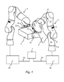
- FIG. 1 is a first force / torque-controlled manipulator 1a and a second force / torque-controlled manipulator 1b shown.
- it is in the illustrated manipulators 1a and 1b to lightweight robot of the type KUKA LBR III.
- Each manipulator 1 a and 1 b has an end effector 3 on its hand flange 2 a, 2 b.
- the end effector 3 may also be referred to as a gripper.
- the manipulator 1a is set up for manually guided movement and carries a first gripper half 3a.
- the second manipulator 1b is automatically activated and carries a second gripper half 3b.
- the manipulators 1a and 1b have members 12 which are connected to each other by joints 8. By moving the joints 8 of the manipulators 1a and 1b, the end effectors 3a and 3b are moved alone or together with a workpiece 4.
- the manually guided manipulator 1a is connected to a first control device 5a.
- the automatically controlled manipulator 1b is connected to a second control device 5b.
- Both control devices 5a, 5b are connected to a common control computer 7, for example a PC, via interface connections 6a and 6b, which may be, for example, (fast-research-interface; FRI) interfaces.
- FRI fast-research-interface
- a control program OROCOS
- the manipulator 1 a In the exemplary embodiment shown, the manipulator 1 a, indicated schematically by the human hand 9, manually guided.
- the control device 5a is set up to operate the manually guided manipulator 1a in at least one of its degrees of freedom and / or torque-controlled and to automatically control a second manipulator 1b as a function of the first force and / or torque-controlled manipulator 1a.
- the control device 5a is set up in the application example to the manipulator 1a in at least one of its degrees of freedom by means of compliance control operate and automatically control the second manipulator 1b in response to the compliance-controlled manipulator 1a.
- the control devices 5a, 5b, 7 are set up to allow the automatically controlled manipulator 1b to perform a movement mirrored to the manually guided manipulator 1a. The movements are executed here in particular at the same time.
- the first manipulator 1a is manually brought to the workpiece 4 by means of the hand 9 of a user.
- the user applies a gripper half 3a of the manipulator 1a to one of two opposite side walls of the workpiece 4.
- the second manipulator 1b with its gripper half 3b moves in mirror symmetry to the opposite side wall of the workpiece 4.
- the workpiece 4 is clamped between the two gripper halves 3a, 3b and can be moved or raised, for example.
- a clamping force may be previously defined, i. be specified.
- known workpieces 4 can be detected by means of at least one force / torque-controlled manipulator 1a, that the current distance corresponds, for example, the two gripper halves 3a and 3b of the workpiece width and then the at least two manipulators 1a and 1b are driven, a force from the workpiece 4th exercise.
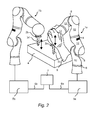
- FIG. 2 another example of application is shown.
- the manually guided manipulator 1a is locked by the control devices 5a in the three spatial rotations and can only perform translational movements. This ensures the tool handled by the manipulator 1a, for example a drill 3c, always impinges perpendicular to the flat workpiece 4.
- the manipulator 1a can be moved manually to the desired location for the bore of the workpiece 4 by means of a hand 9 of the user translational.
- the automatically controlled manipulator 1b moves its drill 3d to a second location of the workpiece 4 in order to automatically introduce a bore, which is symmetrical to the first bore, into the workpiece 4.
- the automatically controlled manipulator 1b requires no limitation of its degrees of freedom, for example, no limitation or blocking of its rotations, since by blocking the rotations of the manually guided manipulator 1a, the automatically controlled manipulator 1b can not perform any rotations. Consequently, the second bore made by the drill 3d has the same quality as the first bore of the first drill 3c.
- FIG. 3 an embodiment of a method according to the invention is shown schematically.
- a manually guided movement of at least one first manipulator (1a) takes place in at least one of its degrees of freedom.
- the manual approach can, according to a method step S3, be a feeding of a tool, in particular a gripper or a gripper half, held by the at least one manipulator (1a, 1b) to the workpiece.
- a second method step S2 an automatic control of at least one second manipulator (1b) takes place as a function of the manually guided manipulator.
- the automatic In accordance with a method step S4, it is possible to bring it into line with a further tool held by the at least one further manipulator (1b), in particular another gripper or a further gripper half (3a, 3b).
- a third method step S6 the workpiece (4) is clamped between one gripper half (3a) of the manually guided manipulator (1a) and the other gripper half (3b) of the automatically controlled further manipulator (1b).
- a fourth method step S5 a common processing and / or movement of the same workpiece (4) by the cooperating manipulators (1a, 1b) can take place by manually guiding at least one of the manipulators (1a, 1b) and / or the workpiece (4).
Landscapes
- Engineering & Computer Science (AREA)
- Robotics (AREA)
- Mechanical Engineering (AREA)
- Physics & Mathematics (AREA)
- General Physics & Mathematics (AREA)
- Automation & Control Theory (AREA)
- Manipulator (AREA)
- Feeding Of Workpieces (AREA)
Applications Claiming Priority (1)
| Application Number | Priority Date | Filing Date | Title |
|---|---|---|---|
| DE102010029745A DE102010029745A1 (de) | 2010-06-07 | 2010-06-07 | Werkstück-Handhabungssystem und Verfahren zum Manipulieren von Werkstücken mittels kooperierender Manipulatoren |
Publications (3)
| Publication Number | Publication Date |
|---|---|
| EP2392435A2 true EP2392435A2 (fr) | 2011-12-07 |
| EP2392435A3 EP2392435A3 (fr) | 2013-05-01 |
| EP2392435B1 EP2392435B1 (fr) | 2020-12-23 |
Family
ID=44834984
Family Applications (1)
| Application Number | Title | Priority Date | Filing Date |
|---|---|---|---|
| EP11168345.4A Not-in-force EP2392435B1 (fr) | 2010-06-07 | 2011-06-01 | Système de manipulation de pièces usinées et procédé de manipulation de pièces usinées à l'aide de manipulateurs coopérants |
Country Status (3)
| Country | Link |
|---|---|
| EP (1) | EP2392435B1 (fr) |
| DE (1) | DE102010029745A1 (fr) |
| DK (1) | DK2392435T3 (fr) |
Cited By (47)
| Publication number | Priority date | Publication date | Assignee | Title |
|---|---|---|---|---|
| EP2664412A3 (fr) * | 2012-05-18 | 2015-03-04 | KUKA Systems GmbH | Dispositif de montage et cellule de montage |
| DE102013220798A1 (de) | 2013-10-15 | 2015-04-16 | Kuka Laboratories Gmbh | Verfahren zum Handhaben von Objekten mittels wenigstens zweier Industrieroboter, und zugehöriger Industrieroboter |
| WO2015086722A1 (fr) * | 2013-12-13 | 2015-06-18 | Kuka Systems Gmbh | Dispositif et procédé de travail |
| WO2015158612A1 (fr) * | 2014-04-15 | 2015-10-22 | Kuka Systems Gmbh | Dispositif robot présentant un axe linéaire |
| EP2919085A3 (fr) * | 2014-03-11 | 2016-06-29 | KUKA Systems GmbH | Procédé de fonctionnement d'un robot |
| CN105751197A (zh) * | 2016-04-26 | 2016-07-13 | 哈尔滨工程大学 | 一种用于主从姿态控制的辅助机构及控制方法 |
| WO2016150907A1 (fr) * | 2015-03-23 | 2016-09-29 | Kuka Roboter Gmbh | Procédé de fonctionnement intuitif robuste par commande tactile d'un manipulateur |
| EP3170425A1 (fr) * | 2015-11-19 | 2017-05-24 | Khaled A.M.A.A. Al-Khulaifi | Système de support de sèche-cheveux robotique avec suivi |
| US9713509B2 (en) | 2013-10-24 | 2017-07-25 | Auris Surgical Robotics, Inc. | Instrument device manipulator with back-mounted tool attachment mechanism |
| US9737371B2 (en) * | 2014-09-30 | 2017-08-22 | Auris Surgical Robotics, Inc. | Configurable robotic surgical system with virtual rail and flexible endoscope |
| US9763741B2 (en) | 2013-10-24 | 2017-09-19 | Auris Surgical Robotics, Inc. | System for robotic-assisted endolumenal surgery and related methods |
| US9788910B2 (en) | 2014-07-01 | 2017-10-17 | Auris Surgical Robotics, Inc. | Instrument-mounted tension sensing mechanism for robotically-driven medical instruments |
| US10016900B1 (en) | 2017-10-10 | 2018-07-10 | Auris Health, Inc. | Surgical robotic arm admittance control |
| US10145747B1 (en) | 2017-10-10 | 2018-12-04 | Auris Health, Inc. | Detection of undesirable forces on a surgical robotic arm |
| US10143526B2 (en) | 2015-11-30 | 2018-12-04 | Auris Health, Inc. | Robot-assisted driving systems and methods |
| US10299870B2 (en) | 2017-06-28 | 2019-05-28 | Auris Health, Inc. | Instrument insertion compensation |
| US10314463B2 (en) | 2014-10-24 | 2019-06-11 | Auris Health, Inc. | Automated endoscope calibration |
| US10426559B2 (en) | 2017-06-30 | 2019-10-01 | Auris Health, Inc. | Systems and methods for medical instrument compression compensation |
| CN110582381A (zh) * | 2017-04-23 | 2019-12-17 | 富兰卡爱米卡股份有限公司 | 用于对电性构件进行电性检查的装置和方法 |
| US10518405B2 (en) | 2016-06-29 | 2019-12-31 | Abb Schweiz Ag | Industrial robot system comprising a dual arm robot |
| US10583271B2 (en) | 2012-11-28 | 2020-03-10 | Auris Health, Inc. | Method of anchoring pullwire directly articulatable region in catheter |
| US10631949B2 (en) | 2015-09-09 | 2020-04-28 | Auris Health, Inc. | Instrument device manipulator with back-mounted tool attachment mechanism |
| WO2020157185A1 (fr) * | 2019-01-30 | 2020-08-06 | Franka Emika Gmbh | Coordination de deux manipulateurs de robot coordonnés |
| WO2020157186A1 (fr) * | 2019-01-31 | 2020-08-06 | Franka Emika Gmbh | Processus d'apprentissage pour un système robotique composé de deux manipulateurs robotiques |
| WO2020157187A1 (fr) * | 2019-01-31 | 2020-08-06 | Franka Emika Gmbh | Coordination de trajectoires de deux robots manipulateurs |
| US10765487B2 (en) | 2018-09-28 | 2020-09-08 | Auris Health, Inc. | Systems and methods for docking medical instruments |
| US10765303B2 (en) | 2018-02-13 | 2020-09-08 | Auris Health, Inc. | System and method for driving medical instrument |
| US10792464B2 (en) | 2014-07-01 | 2020-10-06 | Auris Health, Inc. | Tool and method for using surgical endoscope with spiral lumens |
| US10813539B2 (en) | 2016-09-30 | 2020-10-27 | Auris Health, Inc. | Automated calibration of surgical instruments with pull wires |
| US10912924B2 (en) | 2014-03-24 | 2021-02-09 | Auris Health, Inc. | Systems and devices for catheter driving instinctiveness |
| EP2851162B1 (fr) * | 2013-09-19 | 2021-03-31 | KUKA Deutschland GmbH | Procédé de réglage manuel de la pose d'un bras manipulateur d'un robot industriel et robot industriel associé |
| CN112689551A (zh) * | 2018-09-14 | 2021-04-20 | 海拉有限双合股份公司 | 带有第一和第二机器人的设备及用于运行所述设备的方法 |
| US10987179B2 (en) | 2017-12-06 | 2021-04-27 | Auris Health, Inc. | Systems and methods to correct for uncommanded instrument roll |
| US11510736B2 (en) | 2017-12-14 | 2022-11-29 | Auris Health, Inc. | System and method for estimating instrument location |
| US11529129B2 (en) | 2017-05-12 | 2022-12-20 | Auris Health, Inc. | Biopsy apparatus and system |
| US11684758B2 (en) | 2011-10-14 | 2023-06-27 | Intuitive Surgical Operations, Inc. | Catheter with removable vision probe |
| EP4007679A4 (fr) * | 2019-08-02 | 2023-08-09 | Dextrous Robotics, Inc. | Manipulateurs robotisés |
| US11771309B2 (en) | 2016-12-28 | 2023-10-03 | Auris Health, Inc. | Detecting endolumenal buckling of flexible instruments |
| CN116869770A (zh) * | 2023-07-11 | 2023-10-13 | 上海大学 | 一种双机协作上肢康复机器人的控制方法及系统 |
| US11845184B2 (en) | 2022-04-18 | 2023-12-19 | Dextrous Robotics, Inc. | System and/or method for grasping objects |
| CN117601117A (zh) * | 2023-11-02 | 2024-02-27 | 同济大学 | 一种基于协同阻抗的多机器人协调搬运控制方法 |
| US11918340B2 (en) | 2011-10-14 | 2024-03-05 | Intuitive Surgical Opeartions, Inc. | Electromagnetic sensor with probe and guide sensing elements |
| US12076100B2 (en) | 2018-09-28 | 2024-09-03 | Auris Health, Inc. | Robotic systems and methods for concomitant endoscopic and percutaneous medical procedures |
| US12127797B2 (en) | 2011-10-14 | 2024-10-29 | Intuitive Surgical Operations, Inc. | Catheter sensor systems |
| US12390618B2 (en) | 2011-10-14 | 2025-08-19 | Intuitive Surgical Operations, Inc. | Catheters with control modes for interchangeable probes |
| US12414823B2 (en) | 2019-12-31 | 2025-09-16 | Auris Health, Inc. | Anatomical feature tracking |
| US12414686B2 (en) | 2020-03-30 | 2025-09-16 | Auris Health, Inc. | Endoscopic anatomical feature tracking |
Families Citing this family (15)
| Publication number | Priority date | Publication date | Assignee | Title |
|---|---|---|---|---|
| DE102012015756A1 (de) | 2012-08-08 | 2013-03-21 | Daimler Ag | Verfahren zum Manipulieren zumindest eines Obiekts mittels wenigstens zweier Roboter |
| DE102014204452A1 (de) * | 2014-03-11 | 2015-09-17 | Kuka Systems Gmbh | Verfahren zum Betreiben eines Roboters und zugehöriger Robotermit einer mechanischen Tastvorrichtung |
| JP5893664B2 (ja) | 2014-04-14 | 2016-03-23 | ファナック株式会社 | 作用された力に応じて移動されるロボットを制御するロボット制御装置 |
| JP5893666B2 (ja) | 2014-04-14 | 2016-03-23 | ファナック株式会社 | 力に応じて動かすロボットのロボット制御装置およびロボットシステム |
| DE102014216514B3 (de) * | 2014-08-20 | 2015-09-10 | Kuka Roboter Gmbh | Verfahren zum Programmieren eines Industrieroboters und zugehöriger Industrieroboter |
| JP6706489B2 (ja) | 2015-11-24 | 2020-06-10 | 川崎重工業株式会社 | ロボットのダイレクト教示方法 |
| WO2018091103A1 (fr) * | 2016-11-18 | 2018-05-24 | Abb Schweiz Ag | Système de bras de robot et procédé de manipulation d'un objet par un système de bras de robot pendant la programmation manuelle |
| JP6826069B2 (ja) | 2018-04-18 | 2021-02-03 | ファナック株式会社 | ロボットの動作教示装置、ロボットシステムおよびロボット制御装置 |
| DE102019216229B4 (de) * | 2019-10-07 | 2022-11-10 | Robert Bosch Gmbh | Vorrichtung und Verfahren zum Steuern einer Robotervorrichtung |
| DE102019216560B4 (de) | 2019-10-28 | 2022-01-13 | Robert Bosch Gmbh | Verfahren und Vorrichtung zum Trainieren von Manipulationsfertigkeiten eines Robotersystems |
| DE102019135810B3 (de) | 2019-12-27 | 2020-10-29 | Franka Emika Gmbh | Erzeugung eines Steuerprogramms für einen Robotermanipulator |
| EP4084720A4 (fr) | 2019-12-31 | 2024-01-17 | Auris Health, Inc. | Techniques d'alignement pour un accès percutané |
| CN114929148B (zh) | 2019-12-31 | 2024-05-10 | 奥瑞斯健康公司 | 用于经皮进入的对准界面 |
| DE102020107612B3 (de) | 2020-03-19 | 2021-09-16 | Franka Emika Gmbh | Adaptive Eingabevorrichtung |
| DE102023127790A1 (de) * | 2023-10-11 | 2025-04-17 | fsk industries GmbH & Co. KG | Roboterarmsteuerung mit haptischer Rückmeldung an einen Bediener bei Steuerung |
Citations (1)
| Publication number | Priority date | Publication date | Assignee | Title |
|---|---|---|---|---|
| EP1462895A1 (fr) | 2003-03-28 | 2004-09-29 | KUKA Roboter GmbH | Procédé et dispositif de commande d'une pluralité de manipulateurs |
Family Cites Families (9)
| Publication number | Priority date | Publication date | Assignee | Title |
|---|---|---|---|---|
| US4826392A (en) * | 1986-03-31 | 1989-05-02 | California Institute Of Technology | Method and apparatus for hybrid position/force control of multi-arm cooperating robots |
| JP2667153B2 (ja) * | 1986-07-29 | 1997-10-27 | 松下電器産業株式会社 | 複腕装置の直接教示方法 |
| US5023808A (en) * | 1987-04-06 | 1991-06-11 | California Institute Of Technology | Dual-arm manipulators with adaptive control |
| DD277230A1 (de) * | 1988-11-23 | 1990-03-28 | Adw Ddr Kybernetik Inf | Zweiarmiger industrieroboter |
| JP3783253B2 (ja) * | 1995-09-20 | 2006-06-07 | 株式会社安川電機 | 複数ロボットの同調制御方法 |
| US6804580B1 (en) * | 2003-04-03 | 2004-10-12 | Kuka Roboter Gmbh | Method and control system for controlling a plurality of robots |
| DE602004019781D1 (de) * | 2003-06-20 | 2009-04-16 | Fanuc Robotics America Inc | Mehrfach-roboterarm-verfolgung und spiegel-jog |
| EP1987406B1 (fr) * | 2006-02-23 | 2010-08-04 | Abb Ab | Systeme de commande de la position et de l'orientation d'un objet en fonction de forces et de couples reçus d'un utilisateur |
| DE102008027008B4 (de) * | 2008-06-06 | 2016-03-17 | Kuka Roboter Gmbh | Verfahren und Vorrichtung zum Steuern eines Manipulators |
-
2010
- 2010-06-07 DE DE102010029745A patent/DE102010029745A1/de not_active Ceased
-
2011
- 2011-06-01 EP EP11168345.4A patent/EP2392435B1/fr not_active Not-in-force
- 2011-06-01 DK DK11168345.4T patent/DK2392435T3/da active
Patent Citations (1)
| Publication number | Priority date | Publication date | Assignee | Title |
|---|---|---|---|---|
| EP1462895A1 (fr) | 2003-03-28 | 2004-09-29 | KUKA Roboter GmbH | Procédé et dispositif de commande d'une pluralité de manipulateurs |
Cited By (93)
| Publication number | Priority date | Publication date | Assignee | Title |
|---|---|---|---|---|
| US11684758B2 (en) | 2011-10-14 | 2023-06-27 | Intuitive Surgical Operations, Inc. | Catheter with removable vision probe |
| US12539400B2 (en) | 2011-10-14 | 2026-02-03 | Intuitive Surgical Operations, Inc. | Catheter with removable vision probe |
| US12390618B2 (en) | 2011-10-14 | 2025-08-19 | Intuitive Surgical Operations, Inc. | Catheters with control modes for interchangeable probes |
| US12127797B2 (en) | 2011-10-14 | 2024-10-29 | Intuitive Surgical Operations, Inc. | Catheter sensor systems |
| US11918340B2 (en) | 2011-10-14 | 2024-03-05 | Intuitive Surgical Opeartions, Inc. | Electromagnetic sensor with probe and guide sensing elements |
| EP2664412A3 (fr) * | 2012-05-18 | 2015-03-04 | KUKA Systems GmbH | Dispositif de montage et cellule de montage |
| US10583271B2 (en) | 2012-11-28 | 2020-03-10 | Auris Health, Inc. | Method of anchoring pullwire directly articulatable region in catheter |
| US12350449B2 (en) | 2012-11-28 | 2025-07-08 | Auris Health, Inc. | Method of anchoring pullwire directly articulatable region in catheter |
| US11925774B2 (en) | 2012-11-28 | 2024-03-12 | Auris Health, Inc. | Method of anchoring pullwire directly articulatable region in catheter |
| EP2851162B1 (fr) * | 2013-09-19 | 2021-03-31 | KUKA Deutschland GmbH | Procédé de réglage manuel de la pose d'un bras manipulateur d'un robot industriel et robot industriel associé |
| DE102013220798A1 (de) | 2013-10-15 | 2015-04-16 | Kuka Laboratories Gmbh | Verfahren zum Handhaben von Objekten mittels wenigstens zweier Industrieroboter, und zugehöriger Industrieroboter |
| US9821456B2 (en) | 2013-10-15 | 2017-11-21 | Kuka Roboter Gmbh | Method for the manipulation of objects by means of at least two industrial robots, and associated industrial robot |
| EP2862677A1 (fr) | 2013-10-15 | 2015-04-22 | KUKA Laboratories GmbH | Procédé de manipulation d'objets au moyen d'au moins deux robots industriels et installation de robots industriels correspondante |
| US9713509B2 (en) | 2013-10-24 | 2017-07-25 | Auris Surgical Robotics, Inc. | Instrument device manipulator with back-mounted tool attachment mechanism |
| US9763741B2 (en) | 2013-10-24 | 2017-09-19 | Auris Surgical Robotics, Inc. | System for robotic-assisted endolumenal surgery and related methods |
| US12491042B2 (en) | 2013-10-24 | 2025-12-09 | Auris Health, Inc. | Endoscopic device with helical lumen design |
| US10219874B2 (en) | 2013-10-24 | 2019-03-05 | Auris Health, Inc. | Instrument device manipulator with tension sensing apparatus |
| US9993313B2 (en) | 2013-10-24 | 2018-06-12 | Auris Health, Inc. | Instrument device manipulator with roll mechanism |
| WO2015086722A1 (fr) * | 2013-12-13 | 2015-06-18 | Kuka Systems Gmbh | Dispositif et procédé de travail |
| EP2919085A3 (fr) * | 2014-03-11 | 2016-06-29 | KUKA Systems GmbH | Procédé de fonctionnement d'un robot |
| US10912924B2 (en) | 2014-03-24 | 2021-02-09 | Auris Health, Inc. | Systems and devices for catheter driving instinctiveness |
| WO2015158612A1 (fr) * | 2014-04-15 | 2015-10-22 | Kuka Systems Gmbh | Dispositif robot présentant un axe linéaire |
| US10792464B2 (en) | 2014-07-01 | 2020-10-06 | Auris Health, Inc. | Tool and method for using surgical endoscope with spiral lumens |
| US12447308B2 (en) | 2014-07-01 | 2025-10-21 | Auris Health, Inc. | Multiple-pull-wire robotic instrument articulation |
| US11759605B2 (en) | 2014-07-01 | 2023-09-19 | Auris Health, Inc. | Tool and method for using surgical endoscope with spiral lumens |
| US9788910B2 (en) | 2014-07-01 | 2017-10-17 | Auris Surgical Robotics, Inc. | Instrument-mounted tension sensing mechanism for robotically-driven medical instruments |
| EP3200718A4 (fr) * | 2014-09-30 | 2018-04-25 | Auris Surgical Robotics, Inc | Système chirurgical robotique configurable ayant un rail virtuel et un endoscope souple |
| US9737371B2 (en) * | 2014-09-30 | 2017-08-22 | Auris Surgical Robotics, Inc. | Configurable robotic surgical system with virtual rail and flexible endoscope |
| US20170340396A1 (en) * | 2014-09-30 | 2017-11-30 | Auris Surgical Robotics, Inc. | Configurable robotic surgical system with virtual rail and flexible endoscope |
| US11534250B2 (en) | 2014-09-30 | 2022-12-27 | Auris Health, Inc. | Configurable robotic surgical system with virtual rail and flexible endoscope |
| US10667871B2 (en) | 2014-09-30 | 2020-06-02 | Auris Health, Inc. | Configurable robotic surgical system with virtual rail and flexible endoscope |
| US12575899B2 (en) * | 2014-09-30 | 2026-03-17 | Auris Health, Inc. | Manual and robotic end effector movement coordination |
| CN107427327A (zh) * | 2014-09-30 | 2017-12-01 | 奥瑞斯外科手术机器人公司 | 具有虚拟轨迹和柔性内窥镜的可配置机器人外科手术系统 |
| US10314463B2 (en) | 2014-10-24 | 2019-06-11 | Auris Health, Inc. | Automated endoscope calibration |
| US10635074B2 (en) | 2015-03-23 | 2020-04-28 | Kuka Deutschland Gmbh | Robust intuitive operating method by touching a manipulator |
| WO2016150907A1 (fr) * | 2015-03-23 | 2016-09-29 | Kuka Roboter Gmbh | Procédé de fonctionnement intuitif robuste par commande tactile d'un manipulateur |
| US12075974B2 (en) | 2015-06-26 | 2024-09-03 | Auris Health, Inc. | Instrument calibration |
| US11141048B2 (en) | 2015-06-26 | 2021-10-12 | Auris Health, Inc. | Automated endoscope calibration |
| US11771521B2 (en) | 2015-09-09 | 2023-10-03 | Auris Health, Inc. | Instrument device manipulator with roll mechanism |
| US10786329B2 (en) | 2015-09-09 | 2020-09-29 | Auris Health, Inc. | Instrument device manipulator with roll mechanism |
| US10631949B2 (en) | 2015-09-09 | 2020-04-28 | Auris Health, Inc. | Instrument device manipulator with back-mounted tool attachment mechanism |
| EP3170425A1 (fr) * | 2015-11-19 | 2017-05-24 | Khaled A.M.A.A. Al-Khulaifi | Système de support de sèche-cheveux robotique avec suivi |
| US10806535B2 (en) | 2015-11-30 | 2020-10-20 | Auris Health, Inc. | Robot-assisted driving systems and methods |
| US10143526B2 (en) | 2015-11-30 | 2018-12-04 | Auris Health, Inc. | Robot-assisted driving systems and methods |
| US10813711B2 (en) | 2015-11-30 | 2020-10-27 | Auris Health, Inc. | Robot-assisted driving systems and methods |
| US11464591B2 (en) | 2015-11-30 | 2022-10-11 | Auris Health, Inc. | Robot-assisted driving systems and methods |
| CN105751197A (zh) * | 2016-04-26 | 2016-07-13 | 哈尔滨工程大学 | 一种用于主从姿态控制的辅助机构及控制方法 |
| US10518405B2 (en) | 2016-06-29 | 2019-12-31 | Abb Schweiz Ag | Industrial robot system comprising a dual arm robot |
| US11712154B2 (en) | 2016-09-30 | 2023-08-01 | Auris Health, Inc. | Automated calibration of surgical instruments with pull wires |
| US12290239B2 (en) | 2016-09-30 | 2025-05-06 | Auris Health, Inc. | Automated calibration of surgical instruments with pull wires |
| US10813539B2 (en) | 2016-09-30 | 2020-10-27 | Auris Health, Inc. | Automated calibration of surgical instruments with pull wires |
| US11771309B2 (en) | 2016-12-28 | 2023-10-03 | Auris Health, Inc. | Detecting endolumenal buckling of flexible instruments |
| CN110582381B (zh) * | 2017-04-23 | 2023-02-17 | 富兰卡爱米卡股份有限公司 | 用于对电性构件进行电性检查的装置和方法 |
| CN110582381A (zh) * | 2017-04-23 | 2019-12-17 | 富兰卡爱米卡股份有限公司 | 用于对电性构件进行电性检查的装置和方法 |
| US11529129B2 (en) | 2017-05-12 | 2022-12-20 | Auris Health, Inc. | Biopsy apparatus and system |
| US12226176B2 (en) | 2017-06-28 | 2025-02-18 | Auris Health, Inc. | Automatic instrument position adjustment |
| US11534247B2 (en) | 2017-06-28 | 2022-12-27 | Auris Health, Inc. | Instrument insertion compensation |
| US10299870B2 (en) | 2017-06-28 | 2019-05-28 | Auris Health, Inc. | Instrument insertion compensation |
| US12076098B2 (en) | 2017-06-30 | 2024-09-03 | Auris Health, Inc. | Systems and methods for medical instrument compression compensation |
| US11666393B2 (en) | 2017-06-30 | 2023-06-06 | Auris Health, Inc. | Systems and methods for medical instrument compression compensation |
| US10426559B2 (en) | 2017-06-30 | 2019-10-01 | Auris Health, Inc. | Systems and methods for medical instrument compression compensation |
| US11280690B2 (en) | 2017-10-10 | 2022-03-22 | Auris Health, Inc. | Detection of undesirable forces on a robotic manipulator |
| US11796410B2 (en) | 2017-10-10 | 2023-10-24 | Auris Health, Inc. | Robotic manipulator force determination |
| US11701783B2 (en) | 2017-10-10 | 2023-07-18 | Auris Health, Inc. | Surgical robotic arm admittance control |
| US10016900B1 (en) | 2017-10-10 | 2018-07-10 | Auris Health, Inc. | Surgical robotic arm admittance control |
| US10145747B1 (en) | 2017-10-10 | 2018-12-04 | Auris Health, Inc. | Detection of undesirable forces on a surgical robotic arm |
| US10434660B2 (en) | 2017-10-10 | 2019-10-08 | Auris Health, Inc. | Surgical robotic arm admittance control |
| US10539478B2 (en) | 2017-10-10 | 2020-01-21 | Auris Health, Inc. | Detection of misalignment of robotic arms |
| US11801105B2 (en) | 2017-12-06 | 2023-10-31 | Auris Health, Inc. | Systems and methods to correct for uncommanded instrument roll |
| US10987179B2 (en) | 2017-12-06 | 2021-04-27 | Auris Health, Inc. | Systems and methods to correct for uncommanded instrument roll |
| US12582485B2 (en) | 2017-12-14 | 2026-03-24 | Auris Health, Inc. | Multiple-input instrument position determination |
| US11510736B2 (en) | 2017-12-14 | 2022-11-29 | Auris Health, Inc. | System and method for estimating instrument location |
| US12029390B2 (en) | 2018-02-13 | 2024-07-09 | Auris Health, Inc. | System and method for driving medical instrument |
| US10765303B2 (en) | 2018-02-13 | 2020-09-08 | Auris Health, Inc. | System and method for driving medical instrument |
| CN112689551A (zh) * | 2018-09-14 | 2021-04-20 | 海拉有限双合股份公司 | 带有第一和第二机器人的设备及用于运行所述设备的方法 |
| US10765487B2 (en) | 2018-09-28 | 2020-09-08 | Auris Health, Inc. | Systems and methods for docking medical instruments |
| US11497568B2 (en) | 2018-09-28 | 2022-11-15 | Auris Health, Inc. | Systems and methods for docking medical instruments |
| US12076100B2 (en) | 2018-09-28 | 2024-09-03 | Auris Health, Inc. | Robotic systems and methods for concomitant endoscopic and percutaneous medical procedures |
| US12588964B2 (en) | 2018-09-28 | 2026-03-31 | Auris Health, Inc. | Medical instrument guidance with robotic systems |
| US12226175B2 (en) | 2018-09-28 | 2025-02-18 | Auris Health, Inc. | Systems and methods for docking medical instruments |
| WO2020157185A1 (fr) * | 2019-01-30 | 2020-08-06 | Franka Emika Gmbh | Coordination de deux manipulateurs de robot coordonnés |
| WO2020157187A1 (fr) * | 2019-01-31 | 2020-08-06 | Franka Emika Gmbh | Coordination de trajectoires de deux robots manipulateurs |
| CN113302026A (zh) * | 2019-01-31 | 2021-08-24 | 富兰卡爱米卡股份有限公司 | 两个机器人机械手的路径的协调 |
| WO2020157186A1 (fr) * | 2019-01-31 | 2020-08-06 | Franka Emika Gmbh | Processus d'apprentissage pour un système robotique composé de deux manipulateurs robotiques |
| US20220072711A1 (en) * | 2019-01-31 | 2022-03-10 | Franka Emika Gmbh | Coordination of paths of two robot manipulators |
| JP2022519248A (ja) * | 2019-01-31 | 2022-03-22 | フランカ エーミカ ゲーエムベーハー | 2つのロボットマニピュレータの経路の調整 |
| EP4007679A4 (fr) * | 2019-08-02 | 2023-08-09 | Dextrous Robotics, Inc. | Manipulateurs robotisés |
| US12414823B2 (en) | 2019-12-31 | 2025-09-16 | Auris Health, Inc. | Anatomical feature tracking |
| US12414686B2 (en) | 2020-03-30 | 2025-09-16 | Auris Health, Inc. | Endoscopic anatomical feature tracking |
| US11845184B2 (en) | 2022-04-18 | 2023-12-19 | Dextrous Robotics, Inc. | System and/or method for grasping objects |
| CN116869770A (zh) * | 2023-07-11 | 2023-10-13 | 上海大学 | 一种双机协作上肢康复机器人的控制方法及系统 |
| CN117601117B (zh) * | 2023-11-02 | 2024-05-24 | 同济大学 | 一种基于协同阻抗的多机器人协调搬运控制方法 |
| CN117601117A (zh) * | 2023-11-02 | 2024-02-27 | 同济大学 | 一种基于协同阻抗的多机器人协调搬运控制方法 |
Also Published As
| Publication number | Publication date |
|---|---|
| DE102010029745A1 (de) | 2011-12-08 |
| DK2392435T3 (da) | 2021-03-22 |
| EP2392435B1 (fr) | 2020-12-23 |
| EP2392435A3 (fr) | 2013-05-01 |
Similar Documents
| Publication | Publication Date | Title |
|---|---|---|
| EP2392435B1 (fr) | Système de manipulation de pièces usinées et procédé de manipulation de pièces usinées à l'aide de manipulateurs coopérants | |
| EP1950010B1 (fr) | Robot et procédé de programmation d'un robot | |
| DE102008027008B4 (de) | Verfahren und Vorrichtung zum Steuern eines Manipulators | |
| DE102005054575B3 (de) | Verfahren zur Regelung eines Roboterarms sowie Roboter zur Durchführung des Verfahrens | |
| DE102020121561B3 (de) | Steuerungsverfahren für ein bilaterales Teleoperationssystem, Controller, Teleoperationssystem und Verwendung des Controllers und/oder des Teleoperationssystems | |
| EP2851162B1 (fr) | Procédé de réglage manuel de la pose d'un bras manipulateur d'un robot industriel et robot industriel associé | |
| DE112016004725B4 (de) | Verfahren zum Teach-ln eines Roboters und Roboterarmsteuervorrichtung | |
| EP2868445B1 (fr) | Procédé de programmation de déroulements de mouvement d'un robot industriel redondant et robot industriel associé | |
| EP3020516B1 (fr) | Determination d'espace de prehension d'un objet a l'aide d'un robot | |
| DE102015004483B4 (de) | Robotersteuerung und Robotersystem zum Bewegen eines Roboters als Reaktion auf eine Kraft | |
| DE102016004841B4 (de) | Verfahren und Vorrichtung zum Festlegen eines Bewegungsablaufs für einen Roboter | |
| DE102018116053A1 (de) | Robotersystem und Roboterlernverfahren | |
| DE102007026299B4 (de) | Industrieroboter und Verfahren zum Programmieren eines Industrieroboters | |
| EP3323026A1 (fr) | Détermination d'une instruction d'entrée pour un robot, qui est entrée en exerçant manuellement une force sur le robot | |
| DE102017220999B4 (de) | Modularer Endeffektor | |
| EP3697580A1 (fr) | Système de robot, dispositif et procédé destinés à l'application d'une force de traitement à un objet | |
| WO2020094879A1 (fr) | Robot et procédé de détermination d'un espace de mouvement au moyen d'un robot | |
| DE102018109329B4 (de) | Mehrgliedrige aktuierte Kinematik, vorzugsweise Roboter, besonders vorzugsweise Knickarmroboter | |
| DE102019131400B4 (de) | Kraftmessung und Krafterzeugung in redundanten Robotermanipulatoren | |
| DE102015209773B3 (de) | Verfahren zur kontinuierlichen Synchronisation einer Pose eines Manipulators und einer Eingabevorrichtung | |
| DE102015117306B4 (de) | Mehrachs-Maus für einen Mehrachsroboter | |
| DE102023100737A1 (de) | Primär- und Sekundär-Robotersystem | |
| DE102017112454A1 (de) | Dynamisches Laser-Touch-Sensing mit dynamischem Multiroboter-User-Frame | |
| DE102015118918B3 (de) | Roboter mit Ansteuerung zur diskretisierten manuellen Eingabe von Positionen und/oder Posen | |
| EP3132331B1 (fr) | Système haptique et procédé pour le faire fonctionner |
Legal Events
| Date | Code | Title | Description |
|---|---|---|---|
| AK | Designated contracting states |
Kind code of ref document: A2 Designated state(s): AL AT BE BG CH CY CZ DE DK EE ES FI FR GB GR HR HU IE IS IT LI LT LU LV MC MK MT NL NO PL PT RO RS SE SI SK SM TR |
|
| AX | Request for extension of the european patent |
Extension state: BA ME |
|
| PUAI | Public reference made under article 153(3) epc to a published international application that has entered the european phase |
Free format text: ORIGINAL CODE: 0009012 |
|
| PUAL | Search report despatched |
Free format text: ORIGINAL CODE: 0009013 |
|
| AK | Designated contracting states |
Kind code of ref document: A3 Designated state(s): AL AT BE BG CH CY CZ DE DK EE ES FI FR GB GR HR HU IE IS IT LI LT LU LV MC MK MT NL NO PL PT RO RS SE SI SK SM TR |
|
| AX | Request for extension of the european patent |
Extension state: BA ME |
|
| RIC1 | Information provided on ipc code assigned before grant |
Ipc: B25J 9/16 20060101AFI20130322BHEP Ipc: G05B 19/423 20060101ALI20130322BHEP |
|
| 17P | Request for examination filed |
Effective date: 20131029 |
|
| RBV | Designated contracting states (corrected) |
Designated state(s): AL AT BE BG CH CY CZ DE DK EE ES FI FR GB GR HR HU IE IS IT LI LT LU LV MC MK MT NL NO PL PT RO RS SE SI SK SM TR |
|
| RAP1 | Party data changed (applicant data changed or rights of an application transferred) |
Owner name: KUKA ROBOTER GMBH |
|
| 17Q | First examination report despatched |
Effective date: 20161004 |
|
| 17Q | First examination report despatched |
Effective date: 20161019 |
|
| STAA | Information on the status of an ep patent application or granted ep patent |
Free format text: STATUS: EXAMINATION IS IN PROGRESS |
|
| RAP1 | Party data changed (applicant data changed or rights of an application transferred) |
Owner name: KUKA DEUTSCHLAND GMBH |
|
| GRAP | Despatch of communication of intention to grant a patent |
Free format text: ORIGINAL CODE: EPIDOSNIGR1 |
|
| STAA | Information on the status of an ep patent application or granted ep patent |
Free format text: STATUS: GRANT OF PATENT IS INTENDED |
|
| INTG | Intention to grant announced |
Effective date: 20200728 |
|
| RIN1 | Information on inventor provided before grant (corrected) |
Inventor name: KURTH, JOHANNES Inventor name: BRUYNINCKX, HERMAN Inventor name: SMITS, RUBEN Inventor name: GUHL, TIM Inventor name: SCHREIBER, GUENTHER Inventor name: BISCHOFF, RAINER |
|
| GRAS | Grant fee paid |
Free format text: ORIGINAL CODE: EPIDOSNIGR3 |
|
| GRAA | (expected) grant |
Free format text: ORIGINAL CODE: 0009210 |
|
| STAA | Information on the status of an ep patent application or granted ep patent |
Free format text: STATUS: THE PATENT HAS BEEN GRANTED |
|
| AK | Designated contracting states |
Kind code of ref document: B1 Designated state(s): AL AT BE BG CH CY CZ DE DK EE ES FI FR GB GR HR HU IE IS IT LI LT LU LV MC MK MT NL NO PL PT RO RS SE SI SK SM TR |
|
| REG | Reference to a national code |
Ref country code: GB Ref legal event code: FG4D Free format text: NOT ENGLISH |
|
| REG | Reference to a national code |
Ref country code: DE Ref legal event code: R096 Ref document number: 502011017018 Country of ref document: DE |
|
| REG | Reference to a national code |
Ref country code: AT Ref legal event code: REF Ref document number: 1347283 Country of ref document: AT Kind code of ref document: T Effective date: 20210115 |
|
| REG | Reference to a national code |
Ref country code: IE Ref legal event code: FG4D Free format text: LANGUAGE OF EP DOCUMENT: GERMAN |
|
| REG | Reference to a national code |
Ref country code: DK Ref legal event code: T3 Effective date: 20210319 |
|
| REG | Reference to a national code |
Ref country code: SE Ref legal event code: TRGR |
|
| PG25 | Lapsed in a contracting state [announced via postgrant information from national office to epo] |
Ref country code: GR Free format text: LAPSE BECAUSE OF FAILURE TO SUBMIT A TRANSLATION OF THE DESCRIPTION OR TO PAY THE FEE WITHIN THE PRESCRIBED TIME-LIMIT Effective date: 20210324 Ref country code: FI Free format text: LAPSE BECAUSE OF FAILURE TO SUBMIT A TRANSLATION OF THE DESCRIPTION OR TO PAY THE FEE WITHIN THE PRESCRIBED TIME-LIMIT Effective date: 20201223 Ref country code: RS Free format text: LAPSE BECAUSE OF FAILURE TO SUBMIT A TRANSLATION OF THE DESCRIPTION OR TO PAY THE FEE WITHIN THE PRESCRIBED TIME-LIMIT Effective date: 20201223 Ref country code: NO Free format text: LAPSE BECAUSE OF FAILURE TO SUBMIT A TRANSLATION OF THE DESCRIPTION OR TO PAY THE FEE WITHIN THE PRESCRIBED TIME-LIMIT Effective date: 20210323 |
|
| REG | Reference to a national code |
Ref country code: NL Ref legal event code: MP Effective date: 20201223 |
|
| PG25 | Lapsed in a contracting state [announced via postgrant information from national office to epo] |
Ref country code: BG Free format text: LAPSE BECAUSE OF FAILURE TO SUBMIT A TRANSLATION OF THE DESCRIPTION OR TO PAY THE FEE WITHIN THE PRESCRIBED TIME-LIMIT Effective date: 20210323 Ref country code: LV Free format text: LAPSE BECAUSE OF FAILURE TO SUBMIT A TRANSLATION OF THE DESCRIPTION OR TO PAY THE FEE WITHIN THE PRESCRIBED TIME-LIMIT Effective date: 20201223 |
|
| PG25 | Lapsed in a contracting state [announced via postgrant information from national office to epo] |
Ref country code: NL Free format text: LAPSE BECAUSE OF FAILURE TO SUBMIT A TRANSLATION OF THE DESCRIPTION OR TO PAY THE FEE WITHIN THE PRESCRIBED TIME-LIMIT Effective date: 20201223 Ref country code: HR Free format text: LAPSE BECAUSE OF FAILURE TO SUBMIT A TRANSLATION OF THE DESCRIPTION OR TO PAY THE FEE WITHIN THE PRESCRIBED TIME-LIMIT Effective date: 20201223 |
|
| REG | Reference to a national code |
Ref country code: LT Ref legal event code: MG9D |
|
| PG25 | Lapsed in a contracting state [announced via postgrant information from national office to epo] |
Ref country code: LT Free format text: LAPSE BECAUSE OF FAILURE TO SUBMIT A TRANSLATION OF THE DESCRIPTION OR TO PAY THE FEE WITHIN THE PRESCRIBED TIME-LIMIT Effective date: 20201223 Ref country code: SK Free format text: LAPSE BECAUSE OF FAILURE TO SUBMIT A TRANSLATION OF THE DESCRIPTION OR TO PAY THE FEE WITHIN THE PRESCRIBED TIME-LIMIT Effective date: 20201223 Ref country code: PT Free format text: LAPSE BECAUSE OF FAILURE TO SUBMIT A TRANSLATION OF THE DESCRIPTION OR TO PAY THE FEE WITHIN THE PRESCRIBED TIME-LIMIT Effective date: 20210423 Ref country code: RO Free format text: LAPSE BECAUSE OF FAILURE TO SUBMIT A TRANSLATION OF THE DESCRIPTION OR TO PAY THE FEE WITHIN THE PRESCRIBED TIME-LIMIT Effective date: 20201223 Ref country code: CZ Free format text: LAPSE BECAUSE OF FAILURE TO SUBMIT A TRANSLATION OF THE DESCRIPTION OR TO PAY THE FEE WITHIN THE PRESCRIBED TIME-LIMIT Effective date: 20201223 Ref country code: EE Free format text: LAPSE BECAUSE OF FAILURE TO SUBMIT A TRANSLATION OF THE DESCRIPTION OR TO PAY THE FEE WITHIN THE PRESCRIBED TIME-LIMIT Effective date: 20201223 Ref country code: SM Free format text: LAPSE BECAUSE OF FAILURE TO SUBMIT A TRANSLATION OF THE DESCRIPTION OR TO PAY THE FEE WITHIN THE PRESCRIBED TIME-LIMIT Effective date: 20201223 |
|
| PG25 | Lapsed in a contracting state [announced via postgrant information from national office to epo] |
Ref country code: PL Free format text: LAPSE BECAUSE OF FAILURE TO SUBMIT A TRANSLATION OF THE DESCRIPTION OR TO PAY THE FEE WITHIN THE PRESCRIBED TIME-LIMIT Effective date: 20201223 |
|
| REG | Reference to a national code |
Ref country code: DE Ref legal event code: R097 Ref document number: 502011017018 Country of ref document: DE |
|
| PG25 | Lapsed in a contracting state [announced via postgrant information from national office to epo] |
Ref country code: IS Free format text: LAPSE BECAUSE OF FAILURE TO SUBMIT A TRANSLATION OF THE DESCRIPTION OR TO PAY THE FEE WITHIN THE PRESCRIBED TIME-LIMIT Effective date: 20210423 |
|
| PG25 | Lapsed in a contracting state [announced via postgrant information from national office to epo] |
Ref country code: IT Free format text: LAPSE BECAUSE OF FAILURE TO SUBMIT A TRANSLATION OF THE DESCRIPTION OR TO PAY THE FEE WITHIN THE PRESCRIBED TIME-LIMIT Effective date: 20201223 Ref country code: AL Free format text: LAPSE BECAUSE OF FAILURE TO SUBMIT A TRANSLATION OF THE DESCRIPTION OR TO PAY THE FEE WITHIN THE PRESCRIBED TIME-LIMIT Effective date: 20201223 |
|
| PLBE | No opposition filed within time limit |
Free format text: ORIGINAL CODE: 0009261 |
|
| STAA | Information on the status of an ep patent application or granted ep patent |
Free format text: STATUS: NO OPPOSITION FILED WITHIN TIME LIMIT |
|
| PG25 | Lapsed in a contracting state [announced via postgrant information from national office to epo] |
Ref country code: ES Free format text: LAPSE BECAUSE OF FAILURE TO SUBMIT A TRANSLATION OF THE DESCRIPTION OR TO PAY THE FEE WITHIN THE PRESCRIBED TIME-LIMIT Effective date: 20201223 |
|
| 26N | No opposition filed |
Effective date: 20210924 |
|
| PG25 | Lapsed in a contracting state [announced via postgrant information from national office to epo] |
Ref country code: MC Free format text: LAPSE BECAUSE OF FAILURE TO SUBMIT A TRANSLATION OF THE DESCRIPTION OR TO PAY THE FEE WITHIN THE PRESCRIBED TIME-LIMIT Effective date: 20201223 |
|
| REG | Reference to a national code |
Ref country code: CH Ref legal event code: PL |
|
| PG25 | Lapsed in a contracting state [announced via postgrant information from national office to epo] |
Ref country code: SI Free format text: LAPSE BECAUSE OF FAILURE TO SUBMIT A TRANSLATION OF THE DESCRIPTION OR TO PAY THE FEE WITHIN THE PRESCRIBED TIME-LIMIT Effective date: 20201223 |
|
| PG25 | Lapsed in a contracting state [announced via postgrant information from national office to epo] |
Ref country code: LU Free format text: LAPSE BECAUSE OF NON-PAYMENT OF DUE FEES Effective date: 20210601 |
|
| PG25 | Lapsed in a contracting state [announced via postgrant information from national office to epo] |
Ref country code: LI Free format text: LAPSE BECAUSE OF NON-PAYMENT OF DUE FEES Effective date: 20210630 Ref country code: IE Free format text: LAPSE BECAUSE OF NON-PAYMENT OF DUE FEES Effective date: 20210601 Ref country code: CH Free format text: LAPSE BECAUSE OF NON-PAYMENT OF DUE FEES Effective date: 20210630 |
|
| PG25 | Lapsed in a contracting state [announced via postgrant information from national office to epo] |
Ref country code: IS Free format text: LAPSE BECAUSE OF FAILURE TO SUBMIT A TRANSLATION OF THE DESCRIPTION OR TO PAY THE FEE WITHIN THE PRESCRIBED TIME-LIMIT Effective date: 20210423 |
|
| REG | Reference to a national code |
Ref country code: AT Ref legal event code: MM01 Ref document number: 1347283 Country of ref document: AT Kind code of ref document: T Effective date: 20210601 |
|
| PG25 | Lapsed in a contracting state [announced via postgrant information from national office to epo] |
Ref country code: AT Free format text: LAPSE BECAUSE OF NON-PAYMENT OF DUE FEES Effective date: 20210601 |
|
| REG | Reference to a national code |
Ref country code: FR Ref legal event code: PLFP Year of fee payment: 13 |
|
| PG25 | Lapsed in a contracting state [announced via postgrant information from national office to epo] |
Ref country code: HU Free format text: LAPSE BECAUSE OF FAILURE TO SUBMIT A TRANSLATION OF THE DESCRIPTION OR TO PAY THE FEE WITHIN THE PRESCRIBED TIME-LIMIT; INVALID AB INITIO Effective date: 20110601 Ref country code: CY Free format text: LAPSE BECAUSE OF FAILURE TO SUBMIT A TRANSLATION OF THE DESCRIPTION OR TO PAY THE FEE WITHIN THE PRESCRIBED TIME-LIMIT Effective date: 20201223 |
|
| PG25 | Lapsed in a contracting state [announced via postgrant information from national office to epo] |
Ref country code: MK Free format text: LAPSE BECAUSE OF FAILURE TO SUBMIT A TRANSLATION OF THE DESCRIPTION OR TO PAY THE FEE WITHIN THE PRESCRIBED TIME-LIMIT Effective date: 20201223 |
|
| PGFP | Annual fee paid to national office [announced via postgrant information from national office to epo] |
Ref country code: FR Payment date: 20240328 Year of fee payment: 14 |
|
| PG25 | Lapsed in a contracting state [announced via postgrant information from national office to epo] |
Ref country code: TR Free format text: LAPSE BECAUSE OF FAILURE TO SUBMIT A TRANSLATION OF THE DESCRIPTION OR TO PAY THE FEE WITHIN THE PRESCRIBED TIME-LIMIT Effective date: 20201223 |
|
| PGFP | Annual fee paid to national office [announced via postgrant information from national office to epo] |
Ref country code: GB Payment date: 20240402 Year of fee payment: 14 |
|
| PGFP | Annual fee paid to national office [announced via postgrant information from national office to epo] |
Ref country code: DE Payment date: 20240328 Year of fee payment: 14 |
|
| PGFP | Annual fee paid to national office [announced via postgrant information from national office to epo] |
Ref country code: DK Payment date: 20240612 Year of fee payment: 14 |
|
| PGFP | Annual fee paid to national office [announced via postgrant information from national office to epo] |
Ref country code: SE Payment date: 20240328 Year of fee payment: 14 Ref country code: BE Payment date: 20240422 Year of fee payment: 14 |
|
| PG25 | Lapsed in a contracting state [announced via postgrant information from national office to epo] |
Ref country code: MT Free format text: LAPSE BECAUSE OF FAILURE TO SUBMIT A TRANSLATION OF THE DESCRIPTION OR TO PAY THE FEE WITHIN THE PRESCRIBED TIME-LIMIT Effective date: 20201223 |
|
| REG | Reference to a national code |
Ref country code: DE Ref legal event code: R119 Ref document number: 502011017018 Country of ref document: DE |
|
| REG | Reference to a national code |
Ref country code: DK Ref legal event code: EBP Effective date: 20250630 |
|
| REG | Reference to a national code |
Ref country code: SE Ref legal event code: EUG |
|
| GBPC | Gb: european patent ceased through non-payment of renewal fee |
Effective date: 20250601 |
|
| REG | Reference to a national code |
Ref country code: BE Ref legal event code: MM Effective date: 20250630 |
|
| PG25 | Lapsed in a contracting state [announced via postgrant information from national office to epo] |
Ref country code: GB Free format text: LAPSE BECAUSE OF NON-PAYMENT OF DUE FEES Effective date: 20250601 |
|
| PG25 | Lapsed in a contracting state [announced via postgrant information from national office to epo] |
Ref country code: DE Free format text: LAPSE BECAUSE OF NON-PAYMENT OF DUE FEES Effective date: 20260101 |
|
| PG25 | Lapsed in a contracting state [announced via postgrant information from national office to epo] |
Ref country code: BE Free format text: LAPSE BECAUSE OF NON-PAYMENT OF DUE FEES Effective date: 20250630 |
|
| PG25 | Lapsed in a contracting state [announced via postgrant information from national office to epo] |
Ref country code: FR Free format text: LAPSE BECAUSE OF NON-PAYMENT OF DUE FEES Effective date: 20250630 |