EP2392524A1 - Dispositif de stockage à travées avec rails de guidage pour un véhicule de rayonnage - Google Patents
Dispositif de stockage à travées avec rails de guidage pour un véhicule de rayonnage Download PDFInfo
- Publication number
- EP2392524A1 EP2392524A1 EP11164625A EP11164625A EP2392524A1 EP 2392524 A1 EP2392524 A1 EP 2392524A1 EP 11164625 A EP11164625 A EP 11164625A EP 11164625 A EP11164625 A EP 11164625A EP 2392524 A1 EP2392524 A1 EP 2392524A1
- Authority
- EP
- European Patent Office
- Prior art keywords
- plane
- channel
- segments
- brackets
- butt joints
- Prior art date
- Legal status (The legal status is an assumption and is not a legal conclusion. Google has not performed a legal analysis and makes no representation as to the accuracy of the status listed.)
- Withdrawn
Links
- 238000003860 storage Methods 0.000 title claims abstract description 29
- 238000009826 distribution Methods 0.000 claims abstract description 40
- 239000002800 charge carrier Substances 0.000 claims abstract description 9
- 239000000969 carrier Substances 0.000 claims description 4
- 238000006073 displacement reaction Methods 0.000 claims description 2
- 108091006146 Channels Proteins 0.000 description 51
- 210000001503 joint Anatomy 0.000 description 41
- 230000008901 benefit Effects 0.000 description 5
- 238000000034 method Methods 0.000 description 3
- 239000000463 material Substances 0.000 description 2
- 238000012946 outsourcing Methods 0.000 description 2
- 230000035939 shock Effects 0.000 description 2
- 238000005452 bending Methods 0.000 description 1
- 239000002131 composite material Substances 0.000 description 1
- 230000036461 convulsion Effects 0.000 description 1
- 230000001419 dependent effect Effects 0.000 description 1
- 230000007257 malfunction Effects 0.000 description 1
- 238000004519 manufacturing process Methods 0.000 description 1
- 238000012986 modification Methods 0.000 description 1
- 230000004048 modification Effects 0.000 description 1
Images



Classifications
-
- B—PERFORMING OPERATIONS; TRANSPORTING
- B65—CONVEYING; PACKING; STORING; HANDLING THIN OR FILAMENTARY MATERIAL
- B65G—TRANSPORT OR STORAGE DEVICES, e.g. CONVEYORS FOR LOADING OR TIPPING, SHOP CONVEYOR SYSTEMS OR PNEUMATIC TUBE CONVEYORS
- B65G1/00—Storing articles, individually or in orderly arrangement, in warehouses or magazines
- B65G1/02—Storage devices
- B65G1/04—Storage devices mechanical
- B65G1/0407—Storage devices mechanical using stacker cranes
- B65G1/0414—Storage devices mechanical using stacker cranes provided with satellite cars adapted to travel in storage racks
-
- B—PERFORMING OPERATIONS; TRANSPORTING
- B65—CONVEYING; PACKING; STORING; HANDLING THIN OR FILAMENTARY MATERIAL
- B65G—TRANSPORT OR STORAGE DEVICES, e.g. CONVEYORS FOR LOADING OR TIPPING, SHOP CONVEYOR SYSTEMS OR PNEUMATIC TUBE CONVEYORS
- B65G1/00—Storing articles, individually or in orderly arrangement, in warehouses or magazines
- B65G1/02—Storage devices
- B65G1/04—Storage devices mechanical
- B65G1/0492—Storage devices mechanical with cars adapted to travel in storage aisles
-
- B—PERFORMING OPERATIONS; TRANSPORTING
- B65—CONVEYING; PACKING; STORING; HANDLING THIN OR FILAMENTARY MATERIAL
- B65G—TRANSPORT OR STORAGE DEVICES, e.g. CONVEYORS FOR LOADING OR TIPPING, SHOP CONVEYOR SYSTEMS OR PNEUMATIC TUBE CONVEYORS
- B65G1/00—Storing articles, individually or in orderly arrangement, in warehouses or magazines
- B65G1/02—Storage devices
- B65G1/04—Storage devices mechanical
- B65G1/06—Storage devices mechanical with means for presenting articles for removal at predetermined position or level
- B65G1/065—Storage devices mechanical with means for presenting articles for removal at predetermined position or level with self propelled cars
Definitions
- the invention relates to a channel storage and a segment for a channel storage and a console for a channel storage.
- a transfer device in the form of a distribution vehicle is used, which is also referred to as a shuttle, sewer vehicle or satellite vehicle.
- the distributor vehicle is designed to undercut, lift and move carriers within the channel in the raised state. So deposits and outsourcing can be made by moving the charge carriers in the channel.
- the present invention seeks to provide an improved channel storage, an improved segment for a channel storage and an improved console for a channel warehouse.
- the second level is used for the storage of charge carriers, wherein the distribution vehicle is designed for the spatial displacement of the charge carriers.
- load carriers is meant, for example, pallets or various types of devices which are capable of receiving or supporting desired items to be stored.
- the first and second runners are each formed by segments arranged one behind the other in the longitudinal direction, wherein butt joints are formed by respective abutting segments.
- the butt joints of the segments of the first running rail are spatially offset relative to the butt joints of the segments of the second running rail.
- the butt joints of the first and second running rails are not arranged at the same height in the direction of travel, but offset from one another, so that the distribution vehicle does not simultaneously overflow the joints on both sides during the movement along the rails.
- This has the advantage that the mechanical load on the distribution vehicle and the rack is considerably reduced, since vibrations of the distribution vehicle resulting from the impact connections are minimized during the method of the distribution vehicle.
- Such mechanical loads can damage or destroy, for example, the electronics and / or mechanics of distribution vehicles, lead to malfunction or, in principle, reduce the service life.
- the butt joints of the segments of the first and second running rail are arranged relative to one another in such a way that with respect to all the wheels of the distributor vehicle it is ensured that never more than one running wheel of the distributor vehicle simultaneously touches or passes over one of the butt joints.
- the mechanical load of the distribution vehicle can also be minimized by suitably the wheels of the distribution vehicle be arranged offset from each other so that any existing with respect to the segments existing butt joints never run over or touched by more than one impeller simultaneously.
- the wheels of the distribution vehicle be arranged offset from each other so that any existing with respect to the segments existing butt joints never run over or touched by more than one impeller simultaneously.
- the second plane is arranged above the first plane.
- the first plane preferably has a horizontal guide plane for guiding the travel movement of the distributor vehicle perpendicular to the movement plane of the distributor vehicle and at least one vertical guide plane for a lateral guidance of the distributor vehicle, wherein the second plane comprises a support plane for the charge carriers and the segments both the first and the have the second level.
- the first and second levels are integrally formed with each other, so that a corresponding assembly cost of the channel storage is minimized.
- plane refers to the profile of the side-by-side rails within a channel, wherein any number of channels can be arranged one above the other or side by side.
- the butt joints on a Schaftung be formed by a zigzag course of the butt joints. Due to the zigzag course, the bending stiffness of the adjacent rail segments is initially increased, since they collide against each other when deflected along the zigzag edges. Further, the use of a zigzagged course of the butt joints has the advantage that forces in the transverse direction of the segments are optimally transmitted evenly at the butt joints on both adjoining segments, because of the zigzag shape ensures that seen in the transverse direction of the segments constantly one of the segments with respect to the other segment acts as a stop. This significantly increases the mechanical durability and stability of a corresponding channel store.
- the channel bearing further comprises brackets, wherein the brackets are formed for fixing the rails to frame braces of the channel.
- brackets are used here, which are hung or screwed, for example, in the corresponding frame braces of the channel, so that hereby easy assembly of the segments is ensured on the consoles.
- the brackets are now arranged so that in the region of the butt joints, the respectively abutting segments both come to lie at least partially on the console.
- This can be linked in particular in connection with a zigzag course of the butt joints, wherein in particular this course exceeds the console at least once in each direction, so that correspondingly abutting rail segments can be placed on both sides of the console. This simplifies the assembly of the rail elements and the manufacture of the console. Furthermore, forces occurring on adjacent segments are evenly distributed to the consoles.
- the consoles are disc-shaped.
- this has the advantage that, despite the guarantee of a permanent edition of directly abutting segments on the consoles a minimal material expenditure in relation to the consoles can be guaranteed ,
- a single discoidal console which, nevertheless, with sufficiently high mechanical stability reduced material costs and the total weight of a corresponding channel warehouse.
- the brackets further comprise at least three attachment points and a recess, wherein the attachment points for non-positive fixation of the segments via angle sections and the recess for partially receiving at least one segment is formed perpendicular to the plane of movement of the distribution vehicle.
- the invention is not limited to three attachment points. It is also possible to use less than three attachment points. Corresponding fastening means may protrude from the segments or be recessed in the segments.
- the first plane has two vertical guide plane for the lateral guidance of the distributor vehicle, wherein the horizontal guide plane and the two vertical guide planes and the support plane are defined by the three attachment points and the recess on the brackets delimited from each other.
- the consoles are designed for the positive engagement of the corresponding segments in the mounted state. This continues to support in a significant way a permanent and safe anti-vibration determination of the segments on the consoles.
- the invention relates to a segment for a channel storage described above and a console for a channel storage described above.
- FIG. 1 shows a channel storage 100 with a single channel with an in FIG. 1 unspecified first and second level. However, rails 112 for guiding a traveling movement of a distribution vehicle 106 in the direction 108, ie along the extension direction of the rails 112, are visible.
- channel are a variety of carriers 104, in the present case pallets.
- the distribution vehicle 106 can now be moved by a corresponding movement in the direction 108 along the rails 112 below a pallet 104, whereupon the pallet 104 can be raised by the distribution vehicle in direction 110, and then within the channel in direction 108 by movement of the distribution vehicle to be moved in the direction of 108.
- This is a storage and retrieval of the pallets 104 with their in FIG. 1 not apparent general cargo possible.
- FIG. 1 Further in FIG. 1 can be seen, are frame braces 102, which in conjunction with the rails 112, a stable overall composite of the channel bearing 100 is formed.
- FIG. 2 now shows a cross-sectional view of the channel bearing 100.
- brackets 200 are fixed.
- These brackets 200 serve to receive and fix the rails 112.
- the runners 112 thereby benefit a double function. This is on the one hand the storage of the pallets 104 with their cargo 208 within the plane 212 formed thereby, as well as the leadership of a driving movement of the distribution vehicle 106 perpendicular to the plane of movement of the distribution vehicle.
- the rails 112 serve in the present case for the lateral guidance of the distribution vehicle 106. With its wheels 202, the distribution vehicle 106 is supported on the rails 112 from.
- the rails 112 are attached, for example via angle sections 206 to the brackets 200.
- the transfer vehicle 106 For movement of a pallet 104, as described above, the transfer vehicle 106 is moved under the pallet 104 to be subsequently lifted in the direction 110, whereby a lifting of the pallet 104 from the running rail 112 takes place.
- the pallet 104 may travel along the rails together with the distribution vehicle 106 112 are moved to the pallet 104 then turn off at a desired position again.
- FIG. 3 Now shows a longitudinal sectional view of a channel with respect to the FIGS. 1 and 2 explained channel storage.
- the rails 112 and a remote on the rails 112 pallet 104 are apparent.
- Essential in FIG. 3 is now that the rails 112 are each formed by abutting individual segments.
- the left running rail is formed by segments 301 and 302, which enter at joints 308 corresponding butt joints.
- the right running rail 112 is in FIG. 3 formed by the segments 304 and 306 which abut against respective butt joints 308.
- Sketched in FIG. 3 is further that the butt joints of the segments 301 and 302 are arranged spatially offset from the butt joints of the segments 304 and 306.
- a distribution vehicle has the width of the in FIG. 3 shown pallet 104 and is doing in the view of FIG. 3 Moving from top to bottom, run over wheels of this distribution vehicle first the left butt joint 308, then the right butt joint 308, then the left butt joint 308, etc.
- this method does not overrun the method along the rails 112 on both sides simultaneously the shocks, but offset, which significantly reduces the mechanical load.
- FIG. 3 a Schftung of the butt joints 308 can be seen.
- this Schwarzftung is formed by a zigzag course of the butt joints 308.
- the end portions seen in the longitudinal direction of the segments thus partially engage with each other, whereby, as explained above, the overall stability of the channel bearing is increased.
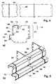
- FIG. 4 the zigzag course of the butt joint 308 is shown in more detail.
- Exemplary is in FIG. 4 the area of the butt joint between the segments 301 and 302 (cf. FIG. 3 ).
- forces acting perpendicularly to the longitudinal direction of the segments 301 and 302 are thus transferred from the segment 301 to the segment 302 and vice versa, whereby forces can be absorbed in a distributed manner by the segments.
- FIG. 5 shows a schematic view of a console 200 ( FIG. 5a ) and a schematic view of consoles 200 with segments 301 and 302 fixed thereto (FIGS. FIG. 5b ).
- the brackets 200 are disc-shaped and serve to fix the rails to frame struts of the channel (see. FIG. 3 ).
- the brackets are arranged so that in the region of the butt joints 308, the respectively abutting segments 301 and 302 both come to lie at least partially on the console. This is also evident in FIG. 3 It can be seen here both in relation to the segments 301 and 302 and with respect to the segments 306 and 308. In the region of the abutment connections 308, both segments 301 and 302 and segments 306 and 304 rest on the same console 200.
- the console 200 has three attachment points 500 and a recess 502, wherein the attachment points 500 for non-positive fixing of the segments 301 and 302 via angle profiles (see. FIG. 2 Angle profile 206) are formed. Furthermore, the recess 502 serves for partially receiving at least one of the segments 301 and 302, respectively, perpendicular to the plane of movement of a corresponding distribution vehicle, ie in the direction 110.
- the channel storage includes first and second levels 210 and 212, respectively FIG. 5a
- the first plane 210 includes two vertical guide planes 508 and 512 for laterally guiding a respective distribution vehicle.
- the first plane comprises a horizontal guide plane 510 for guiding the travel movement of the distributor vehicle perpendicular to the movement plane of the distributor vehicle.
- the second level 212 comprises a support plane 504 for the charge carriers.
- the first and second levels are integrally formed with each other, ie, the first and second levels are each formed together by respective segments 101 and 102, respectively.
- the two vertical guide planes 508 and 512 and the horizontal guide plane 510 and the support plane 504 are defined by the three attachment points 500 and the recess 502 of the bracket 200 separated from each other.
- Console 200 is also designed for the positive engagement of the segment 301 or 312 and thus the running rail 112 in the mounted state on the console 200.
- a part 506 of the segment 301 or 302 engages in the recess 502 of the console 200.
- FIG. 5b perspective view of a running rail 112 consisting of the segments 301 and 302, which have a zigzag course of the butt joint in the region of the butt joint 308.
- FIG. 6 shows a schematic view of an alternative track rail 112.
- This track rail has in contrast to in Fig. 5a shown running rail only two attachment points 500, wherein the attachment points 500 are formed for non-positive fixation of the running rail on the console, not shown here.
- Fig. 6 only serves the vertical guide plane 508 of the lateral guidance of a corresponding distribution vehicle, wherein the horizontal guide plane 510 is used to guide the driving movement of the distribution vehicle perpendicular to the plane of movement of the distribution vehicle.
- the support level 504 is again provided for supporting the charge carrier.
Landscapes
- Engineering & Computer Science (AREA)
- Mechanical Engineering (AREA)
- Warehouses Or Storage Devices (AREA)
Applications Claiming Priority (1)
| Application Number | Priority Date | Filing Date | Title |
|---|---|---|---|
| DE201010029563 DE102010029563B4 (de) | 2010-06-01 | 2010-06-01 | Kanallager |
Publications (1)
| Publication Number | Publication Date |
|---|---|
| EP2392524A1 true EP2392524A1 (fr) | 2011-12-07 |
Family
ID=44583598
Family Applications (1)
| Application Number | Title | Priority Date | Filing Date |
|---|---|---|---|
| EP11164625A Withdrawn EP2392524A1 (fr) | 2010-06-01 | 2011-05-03 | Dispositif de stockage à travées avec rails de guidage pour un véhicule de rayonnage |
Country Status (2)
| Country | Link |
|---|---|
| EP (1) | EP2392524A1 (fr) |
| DE (1) | DE102010029563B4 (fr) |
Cited By (9)
| Publication number | Priority date | Publication date | Assignee | Title |
|---|---|---|---|---|
| WO2013075078A1 (fr) * | 2011-11-20 | 2013-05-23 | Vertique, Inc. | Procédés et système de stockage |
| WO2016102317A1 (fr) * | 2014-12-22 | 2016-06-30 | Weber Maschinenbau Gmbh Breidenbach | Dispositif de déplacement comprenant une configuration de fonctionnement et d'entretien |
| US9725240B2 (en) | 2013-03-14 | 2017-08-08 | Signode Industrial Group Llc | Storage system and methods |
| EP3230178A4 (fr) * | 2014-12-09 | 2018-11-21 | Swisslog Logistics, Inc. | Structure de stockage et de récupération de palette automatisés |
| EP3581522A1 (fr) * | 2018-06-13 | 2019-12-18 | Logevo AB | Système de stockage et agencement de support de transport pré-monté |
| WO2021175872A1 (fr) * | 2020-03-03 | 2021-09-10 | Ocado Innovation Limited | Structure de cadre de grille pour un système de stockage |
| WO2024023090A1 (fr) * | 2022-07-28 | 2024-02-01 | Nedcon B.V. | Entrepôt de stockage et de récupération de marchandises ou de lots de marchandises placés sur des porte-charges |
| CN118597601A (zh) * | 2024-06-18 | 2024-09-06 | 中国科学院微小卫星创新研究院 | 基于阿基米德螺线轨道的卫星天线立体仓储、存取方法 |
| US12617610B2 (en) | 2020-03-03 | 2026-05-05 | Ocado Innovation Limited | Grid framework structure |
Families Citing this family (6)
| Publication number | Priority date | Publication date | Assignee | Title |
|---|---|---|---|---|
| DE102014114978B4 (de) * | 2014-10-15 | 2022-01-05 | Bito-Lagertechnik Bittmann Gmbh | Regallager |
| DE202016106276U1 (de) | 2016-11-10 | 2016-12-09 | Bito-Lagertechnik Bittmann Gmbh | Shuttlelager |
| DE102020117495A1 (de) | 2020-07-02 | 2022-01-05 | Nedcon B.V. | Warenlager für das Ein- und Auslagern von auf Ladungsträgern angeordneten Waren oder Warengebinden |
| DE202020105525U1 (de) | 2020-09-28 | 2022-01-07 | Bito-Lagertechnik Bittmann Gmbh | Shuttlelager |
| CN113306945B (zh) * | 2021-07-13 | 2022-10-18 | 隆链智能科技(上海)有限公司 | 一种凸轮升降式十六轮四向穿梭车 |
| DE102024125017A1 (de) | 2024-09-02 | 2026-03-05 | Nedcon B.V. | Warenlager für das Ein- und Auslagern von auf Ladungsträgern angeordneten Waren oder Warengebinden |
Citations (8)
| Publication number | Priority date | Publication date | Assignee | Title |
|---|---|---|---|---|
| US1333877A (en) * | 1918-08-29 | 1920-03-16 | Ryczek Paul Andrew | Rail-joint |
| GB276445A (en) * | 1926-06-01 | 1927-09-01 | Frederick Cooper | Improvements in rail joints for railways, tramways, and the like |
| DE508235C (de) * | 1929-08-01 | 1930-09-25 | Julius Keller | Weiche fuer Grubenbahnen |
| DE627334C (de) * | 1932-07-19 | 1936-03-14 | Oswald Schmidt | Schienenstossverbindung mit einer zum Teil in Schienenlaengsrichtung sich erstreckenden Stossfuge |
| DE3840648A1 (de) | 1988-12-02 | 1990-06-07 | S Way Ag | Hochregallager-einrichtung |
| DE29905013U1 (de) * | 1999-03-18 | 2000-08-10 | Buck, Martin, Dipl.-Ing., 27404 Zeven | Anlage zum Fördern und Lagern von Paletten |
| EP1554198A1 (fr) * | 2002-10-14 | 2005-07-20 | Eab Ab | Systeme de rails |
| DE102008022323A1 (de) * | 2008-04-30 | 2009-11-12 | SSI Schäfer AG | Shuttle-Kanallager, Shuttle-Bahnhof, Shuttle und Verfahren zum Betreiben des Shuttle-Kanallagers |
Family Cites Families (1)
| Publication number | Priority date | Publication date | Assignee | Title |
|---|---|---|---|---|
| DE29607164U1 (de) * | 1996-04-22 | 1996-07-04 | A Q S Schmale GmbH, 34414 Warburg | Vorrichtung zur verschieblichen Aufnahme von Kästen und ähnlichem |
-
2010
- 2010-06-01 DE DE201010029563 patent/DE102010029563B4/de not_active Expired - Fee Related
-
2011
- 2011-05-03 EP EP11164625A patent/EP2392524A1/fr not_active Withdrawn
Patent Citations (8)
| Publication number | Priority date | Publication date | Assignee | Title |
|---|---|---|---|---|
| US1333877A (en) * | 1918-08-29 | 1920-03-16 | Ryczek Paul Andrew | Rail-joint |
| GB276445A (en) * | 1926-06-01 | 1927-09-01 | Frederick Cooper | Improvements in rail joints for railways, tramways, and the like |
| DE508235C (de) * | 1929-08-01 | 1930-09-25 | Julius Keller | Weiche fuer Grubenbahnen |
| DE627334C (de) * | 1932-07-19 | 1936-03-14 | Oswald Schmidt | Schienenstossverbindung mit einer zum Teil in Schienenlaengsrichtung sich erstreckenden Stossfuge |
| DE3840648A1 (de) | 1988-12-02 | 1990-06-07 | S Way Ag | Hochregallager-einrichtung |
| DE29905013U1 (de) * | 1999-03-18 | 2000-08-10 | Buck, Martin, Dipl.-Ing., 27404 Zeven | Anlage zum Fördern und Lagern von Paletten |
| EP1554198A1 (fr) * | 2002-10-14 | 2005-07-20 | Eab Ab | Systeme de rails |
| DE102008022323A1 (de) * | 2008-04-30 | 2009-11-12 | SSI Schäfer AG | Shuttle-Kanallager, Shuttle-Bahnhof, Shuttle und Verfahren zum Betreiben des Shuttle-Kanallagers |
Non-Patent Citations (1)
| Title |
|---|
| RAIL ROAD INFORMATION SERVICE: "Special bibliography: safety-related technology", 31 March 1973, NATIONAL RESEARCH COUNCIL - NATIONAL ACADEMY OF SCIENCES, Washington DC, article "CHAPTER 01: TRACK AND STRUCTURES", pages: 68, XP002659416, 73S1 * |
Cited By (16)
| Publication number | Priority date | Publication date | Assignee | Title |
|---|---|---|---|---|
| US11897694B2 (en) | 2011-11-20 | 2024-02-13 | Signode Industrial Group Llc | Storage system and methods |
| US10974898B2 (en) | 2011-11-20 | 2021-04-13 | Signode Industrial Group Llc | Storage system and methods |
| US9643781B2 (en) | 2011-11-20 | 2017-05-09 | Illinois Tool Works Inc. | Storage system and methods |
| US10526143B2 (en) | 2011-11-20 | 2020-01-07 | Signode Industrial Group Llc | Storage system and methods |
| US12421038B2 (en) | 2011-11-20 | 2025-09-23 | Signode Industrial Group Llc | Storage system and methods |
| WO2013075078A1 (fr) * | 2011-11-20 | 2013-05-23 | Vertique, Inc. | Procédés et système de stockage |
| US11492198B2 (en) | 2011-11-20 | 2022-11-08 | Signode Industrial Group Llc | Storage system and methods |
| US9725240B2 (en) | 2013-03-14 | 2017-08-08 | Signode Industrial Group Llc | Storage system and methods |
| EP3230178A4 (fr) * | 2014-12-09 | 2018-11-21 | Swisslog Logistics, Inc. | Structure de stockage et de récupération de palette automatisés |
| US10569973B2 (en) | 2014-12-22 | 2020-02-25 | Weber Maschinenbau Gmbh Breidenbach | Moving device having an operating configuration and a maintenance configuration |
| WO2016102317A1 (fr) * | 2014-12-22 | 2016-06-30 | Weber Maschinenbau Gmbh Breidenbach | Dispositif de déplacement comprenant une configuration de fonctionnement et d'entretien |
| EP3581522A1 (fr) * | 2018-06-13 | 2019-12-18 | Logevo AB | Système de stockage et agencement de support de transport pré-monté |
| WO2021175872A1 (fr) * | 2020-03-03 | 2021-09-10 | Ocado Innovation Limited | Structure de cadre de grille pour un système de stockage |
| US12617610B2 (en) | 2020-03-03 | 2026-05-05 | Ocado Innovation Limited | Grid framework structure |
| WO2024023090A1 (fr) * | 2022-07-28 | 2024-02-01 | Nedcon B.V. | Entrepôt de stockage et de récupération de marchandises ou de lots de marchandises placés sur des porte-charges |
| CN118597601A (zh) * | 2024-06-18 | 2024-09-06 | 中国科学院微小卫星创新研究院 | 基于阿基米德螺线轨道的卫星天线立体仓储、存取方法 |
Also Published As
| Publication number | Publication date |
|---|---|
| DE102010029563A1 (de) | 2011-12-01 |
| DE102010029563B4 (de) | 2012-12-06 |
Similar Documents
| Publication | Publication Date | Title |
|---|---|---|
| DE102010029563B4 (de) | Kanallager | |
| DE19726500B4 (de) | Trennvorrichtung für eine Kabelbahn | |
| EP2673218B1 (fr) | Système d'entrepôt à rayonnages | |
| EP2729387B1 (fr) | Système d'entreposage à rayonnages | |
| DE102005048379B4 (de) | Lagerregal mit einer Vielzahl von Regaleinheiten | |
| DE102013114275A1 (de) | Regallagersystem mit Förderfahrzeug-Hebevorrichtung | |
| WO2012106744A1 (fr) | Système de stockage sur rayonnages et son procédé de fonctionnement | |
| DE69422292T2 (de) | Universalträger für eine bewegliche last | |
| DE102017112669A1 (de) | Modulares Lager-Regalsystem | |
| WO2012106747A1 (fr) | Appareil de commande de rayonnages à un niveau pour entrer et sortir des marchandises dans et hors d'un entrepôt à rayonnages | |
| EP3321216A1 (fr) | Palier de navette | |
| EP3296186A1 (fr) | Vehicule utilitaire dote d'une carrosserie et procede de montage d'une carrosserie sur un vehicule utilitaire | |
| DE102020117495A1 (de) | Warenlager für das Ein- und Auslagern von auf Ladungsträgern angeordneten Waren oder Warengebinden | |
| DE4417857C2 (de) | Fixiervorrichtung zur variablen Festlegung von Ladegut | |
| EP2746193A1 (fr) | Entrepôt et appareil de commande d'entrepôt avec fonction de passage | |
| EP1437283A1 (fr) | Chariot de transport, en particulier pour des ustensiles de nettoyage | |
| DE102016102262A1 (de) | Modularer Fahrstraßenrahmen für ein Regallager | |
| DE202005017269U1 (de) | Lagerregal mit einer Vielzahl von Regaleinheiten | |
| EP4703299A1 (fr) | Entrepôt pour le stockage et le déstockage de marchandises ou de gerbes de marchandises disposées sur des supports de charge | |
| EP2392523B1 (fr) | Etagère dotée de rouleaux de centrage | |
| DE9408400U1 (de) | Fixiervorrichtung zur variablen Festlegung von Ladegut | |
| EP1426310B1 (fr) | Transstockeur | |
| DE102016124447A1 (de) | Regalbediengerät | |
| EP4461671A1 (fr) | Agencement d'étagère | |
| AT509458B1 (de) | Regallager mit regalbediengerät |
Legal Events
| Date | Code | Title | Description |
|---|---|---|---|
| AK | Designated contracting states |
Kind code of ref document: A1 Designated state(s): AL AT BE BG CH CY CZ DE DK EE ES FI FR GB GR HR HU IE IS IT LI LT LU LV MC MK MT NL NO PL PT RO RS SE SI SK SM TR |
|
| AX | Request for extension of the european patent |
Extension state: BA ME |
|
| PUAI | Public reference made under article 153(3) epc to a published international application that has entered the european phase |
Free format text: ORIGINAL CODE: 0009012 |
|
| 17P | Request for examination filed |
Effective date: 20111215 |
|
| RIN1 | Information on inventor provided before grant (corrected) |
Inventor name: KEMPERDICK, ARTUR |
|
| 17Q | First examination report despatched |
Effective date: 20130131 |
|
| STAA | Information on the status of an ep patent application or granted ep patent |
Free format text: STATUS: THE APPLICATION IS DEEMED TO BE WITHDRAWN |
|
| 18D | Application deemed to be withdrawn |
Effective date: 20160206 |