EP2392902A1 - Agencement de capteur, dispositif de stockage comprenant un agencement de capteur et procédé de calibrage destiné au calibrage de celui-ci - Google Patents
Agencement de capteur, dispositif de stockage comprenant un agencement de capteur et procédé de calibrage destiné au calibrage de celui-ci Download PDFInfo
- Publication number
- EP2392902A1 EP2392902A1 EP10005742A EP10005742A EP2392902A1 EP 2392902 A1 EP2392902 A1 EP 2392902A1 EP 10005742 A EP10005742 A EP 10005742A EP 10005742 A EP10005742 A EP 10005742A EP 2392902 A1 EP2392902 A1 EP 2392902A1
- Authority
- EP
- European Patent Office
- Prior art keywords
- sensor
- communication unit
- detection
- unit
- plug
- Prior art date
- Legal status (The legal status is an assumption and is not a legal conclusion. Google has not performed a legal analysis and makes no representation as to the accuracy of the status listed.)
- Granted
Links
Images




Classifications
-
- G—PHYSICS
- G01—MEASURING; TESTING
- G01K—MEASURING TEMPERATURE; MEASURING QUANTITY OF HEAT; THERMALLY-SENSITIVE ELEMENTS NOT OTHERWISE PROVIDED FOR
- G01K1/00—Details of thermometers not specially adapted for particular types of thermometer
- G01K1/02—Means for indicating or recording specially adapted for thermometers
- G01K1/026—Means for indicating or recording specially adapted for thermometers arrangements for monitoring a plurality of temperatures, e.g. by multiplexing
-
- G—PHYSICS
- G01—MEASURING; TESTING
- G01K—MEASURING TEMPERATURE; MEASURING QUANTITY OF HEAT; THERMALLY-SENSITIVE ELEMENTS NOT OTHERWISE PROVIDED FOR
- G01K1/00—Details of thermometers not specially adapted for particular types of thermometer
- G01K1/14—Supports; Fastening devices; Arrangements for mounting thermometers in particular locations
-
- G—PHYSICS
- G01—MEASURING; TESTING
- G01K—MEASURING TEMPERATURE; MEASURING QUANTITY OF HEAT; THERMALLY-SENSITIVE ELEMENTS NOT OTHERWISE PROVIDED FOR
- G01K15/00—Testing or calibrating of thermometers
-
- F—MECHANICAL ENGINEERING; LIGHTING; HEATING; WEAPONS; BLASTING
- F25—REFRIGERATION OR COOLING; COMBINED HEATING AND REFRIGERATION SYSTEMS; HEAT PUMP SYSTEMS; MANUFACTURE OR STORAGE OF ICE; LIQUEFACTION SOLIDIFICATION OF GASES
- F25D—REFRIGERATORS; COLD ROOMS; ICE-BOXES; COOLING OR FREEZING APPARATUS NOT OTHERWISE PROVIDED FOR
- F25D2500/00—Problems to be solved
- F25D2500/06—Stock management
Definitions
- the invention relates to a sensor arrangement, comprising at least one sensor, in particular a temperature sensor, a measuring unit containing the measuring electronics, in particular temperature measuring unit, and a detection and communication unit, wherein the at least one sensor with the measuring unit via a first cable connection is connectable and the measuring unit with the
- a storage device in particular a cooling device for storing blood products, comprising a thermally insulated housing with a closable by means of a thermally insulated door access opening and at least one heat unit , wherein the housing encloses a storage space and in the interior of the housing at least one bearing device, preferably in the form of an extendable drawer, is provided, according to the preamble de s claim 14.
- the invention relates to a method for calibrating the sensor arrangement according to claim 18.
- Sensor arrangements with at least one sensor, a measuring unit and a detection and communication unit are already known from the prior art.
- the sensors are usually connected to the measuring unit via a cable connection.
- the measuring unit itself comprising the measuring electronics can be further connected via a cable connection with the detection and communication unit.
- the ends of the cable connection, which is connected to the sensors, are connected directly to the temperature measuring and evaluation unit.
- Storage devices known from the prior art may have such a sensor arrangement.
- the sensor arrangement serves to detect the temperatures in the interior of the storage device.
- several sensors are distributed in the interior of the storage device such that all relevant areas of the interior can be monitored by means of the sensors.
- the user of the storage device now wants to perform a calibration of the entire sensor arrangement comprising the sensors, the measuring electronics and the detection and communication unit, it is possible either to place the sensors of a further calibrated measuring system at the same location of the sensors of the storage device and one Perform comparative measurement, or alternatively replace the entire sensor array. In any case, this is a very time-consuming process and the responsible maintenance personnel or the measuring technician must always work on site at the storage facility.
- the user of the storage device must remove the entire stored and temperature-sensitive stored material or at least parts thereof before calibration from the storage device in order to avoid damage thereof. This becomes all the more complicated the more sensors the sensor arrangement has.
- the objective part of the object is achieved by a sensor arrangement having the features of patent claim 1 and patent claim 14.
- the procedural part of the object is achieved by a method for calibrating the sensor arrangement according to claim.
- the subclaims show advantageous embodiments and further developments of the invention.
- the first cable connection which connects the at least one sensor to the measuring unit, to separate into a first cable section and a second cable section, wherein the first cable section with the second cable section by means of a detachable plug connection is connectable.
- the connector comprises a male connector and a female connector, wherein the male connector is assigned to the first cable section and the female connector to the second cable section.
- the male connector with the female connector via a locking device is connectable, so that an accidental disconnection of the connector is effectively avoided.
- a bayonet closure for quick and effective connection of the male and female plugs.
- the connector is designed as a plug with a low electrical resistance to avoid any interference on the measured data.
- the first cable portion of the first cable connection is connected to the at least one sensor and the second cable portion of the first cable connection to the measuring unit, wherein the first cable portion is shorter than the second cable portion and preferably has a maximum length of 50 cm.
- the length of the second cable section is chosen such that the positioning of the sensor can take place at the predefined position in the measuring range.
- the measuring unit has, according to an embodiment of the subject invention, a plurality of slots for connecting a plurality of sensors, in particular of nine sensors on.
- the number of sensors varies with the desired accuracy of measurement and monitoring of the measuring range.
- the measurement unit and the acquisition and communication unit each have a USB port.
- a detachable USB connection between the measuring unit and the detection and communication unit can be produced.
- USB Universal Serial Bus
- USB a connection between two devices via a serial bus system to understand, while devices are connected to each other and can be separated from each other, with connected devices, and their properties are automatically detected.
- the detection and communication unit also includes a wired Ethernet connection (LAN connection) and / or a wireless connection (WLAN connection) for connecting the detection and communication unit to a computer or a network.
- LAN connection wired Ethernet connection
- WLAN connection wireless connection
- at least one additional USB port is provided for connecting external devices.
- the detection and communication unit includes a memory unit for recording and buffering information. These can be read out in an advantageous manner via the wired Ethernet connection (LAN connection) and / or the wireless connection (WLAN connection). Thus, a control of the detection and communication unit in the context of remote maintenance is possible in particular through the Internet.
- LAN connection wired Ethernet connection
- WLAN connection wireless connection
- a display device for displaying recorded and cached information is also provided. This allows a direct query of the information on site.
- the sensor arrangement has at least one calibration plug, wherein the at least one calibration plug is detachably connectable to the female plug of the plug connection.
- the at least one calibration plug is provided with an integrated precision resistor.
- the storage device can be configured in particular as a cooling device for storing blood products.
- the storage device comprises a heat-insulated housing with a closable by means of a heat-insulated door access opening and at least one heat unit.
- a heat aggregate is understood as meaning both a heat-generating, ie a positive heat flow, and a cold-generating, ie, a negative heat flow, aggregate.
- the housing encloses a storage space and at least one storage device, preferably in the form of an extendable drawer, is provided in the interior of the housing.
- the bearing device is equipped with the sensor arrangement according to the invention.
- At least one extendable sensor insert preferably formed in the form of a perforated plate, is provided inside the housing.
- the at least one sensor insert on at least one sensor holder for releasably holding the at least one sensor.
- the holder can be formed by a simple hole in the sensor insert, in which the sensor is inserted. Alternatively, it can also be provided a detent device, in which the sensor is engaged. Other designs are conceivable, but the sensor must be solvable in each case of the sensor insert
- the second cable connection with the female connector, the measuring unit and the detection and communication unit are fixedly arranged in the housing of the bearing device.
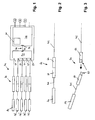
- sensor assembly 1 has a first sensor 10 and four other sensors 10 'for detecting a temperature in a storage room.
- the first cable connection 40 has, as in Fig. 2 shown, a first cable section 41 and a second cable section 42.
- the first cable section 40 is formed separately from the second cable section 42.
- the two cable sections 41 and 42 are connected via a plug connection 60.
- the connector has a male connector 61 and a female connector 62.
- the male connector is connected by means of an Ast driven 63 with the female connector 62 such that an independent release is effectively prevented.
- the measuring unit 20 is further connected to a detection and communication unit 30 via a second cable connection 50.
- the second cable connection 50 is designed as a USB connection.
- both the measuring unit 20 and the detection and communication unit 30 have a USB connection, so that the measuring unit 20 can be connected to the detection and communication unit 30 by means of a USB cable.
- this also has a plurality of slots 21.
- the detection and communication unit 30 also has a plurality of terminals, in particular an Ethernet connection A for connecting the detection and communication unit 30 to an external computer or an external network.
- Ethernet is to be understood as a technology for a wired data network.
- the connection for connecting the detection and communication unit to a separate computer or a separate network can also be done wirelessly via a so-called WLAN connection.
- the detection and communication unit 30 further includes a USB port B for connecting external devices.
- a display device C is connected to the detection and communication unit to be able to display the information processed by the detection and communication unit 30 accordingly.
- the detection and communication unit 30 has a memory unit 31 for recording and buffering information that can also be displayed via the display device C.
- the storage unit 31 serves to store calibration data or measured values acquired by the sensors before they are forwarded to a read-out device (not shown).
- the connector 60 is by removing the male connector 61 from the female connector 62, as in Fig. 3 shown, separable. As such, the sensor 10 including the first cable portion 41 and the male connector 61 can be separated from the second cable portion 42 and the female connector 61 connected to the measuring unit 20.
- the locking device 63 is designed such that it effectively prevents unintentional release of the male connector 61 from the female connector 62. This can be done for example via a bayonet lock.
- the bearing device as in Fig. 4 . 5a and 5b has a housing 100 which encloses a storage space 104.
- the access opening 103 of the housing 101 is closed by a heat-insulated door 102.
- Inside the housing 101 four storage devices 105 are arranged.
- the storage facilities 105 are designed in a drawer shape and extendable out of the access opening 103 of the housing 101.
- the storage facilities 105 serve the storage of items 120 to be stored, such as blood products such as blood plasma or the like.
- sensor bays 110 are provided, which can also be drawer-like pulled out of the interior of the housing 101 through the access opening 103. These are movably supported in lateral guide rails (not shown), so that they are accessible and movable in a simple way. In its retracted position, the sensor bays 110 are secured by a locking device (not shown) in such a way that an independent extension of the sensor bays 110 is effectively prevented.
- the sensor bays 110 are mounted above the respective work volume to be monitored, as in Fig. 5 shown.
- the positions of the sensor holders 111 are selected such that a task-specific detection of the temperatures inside the housing 101 of the bearing device 100 is ensured.
- the first cable section 41 as well as the plug connection 60 and also the second cable section 42 continue to be arranged on the respective sensor insert 110, the latter leaving the individual sensor insert 110 towards the rear wall of the housing, in order there to be in a collecting channel (not shown) with the second cable section 41 of the further cable connections 40 of the additional sensors 10, together to the measuring unit 20 (not shown in FIG Fig. 5b ) to be led.
- the section of the second cable section 41 and the female connector 62 located on the respective sensor insert 110 are fixed in their position on the respective sensor insert 110.
- the single sensor insert 110 is designed to save weight in the form of a thin perforated plate (not shown).
- a return device is provided (not shown), which automatically retracts the sensor insert 110 into the housing 101 as soon as it is released by the user.
- the sensors 10, 10 are connected to the remainder of the system via the connectors 60.
- the measuring unit 20 transfers the measurement data to the detection and communication unit, which transfers it via the Ethernet connection A or a WLAN connection to an external polling station (not shown).
- the sensor arrangement must be readjusted or calibrated.
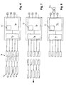
- this calibration takes place via replacement of the sensors 10 'by manufacturer-calibrated new sensors 10 "However, before the system is used in the life mode, calibration of the remainder system is necessary '10' separated from the rest, as in Fig. 7 shown.
- the preparation of the calibration process is then carried out by generating the relevant calibration data and transferring the relevant calibration data to a storage medium 200.
- the relevant calibration data is transferred to the storage unit 31 the acquisition and communication unit 30, which automatically solves the beginning of the calibration process.
- the user When going through the calibration process, the user is prompted to connect a calibration plug 70, 70 'to each female connector 62 of the connector 60.
- the calibration plug 70, 70 ' has a connection corresponding to the male plug 61 (not shown).
- the automatic execution of the calibration process of the residual system consisting of the second cable connections 50, the measuring unit 20 and the detection and communication unit 30 on the basis of the relevant calibration data on the storage unit 30 of the detection and communication unit 30.
- the calibration plugs 70, 70 ' are removed from the female plugs 62 before the storage medium 200 is disconnected from the USB port B of the detection and communication unit 30.
- the calibration data is stored on the memory unit 31 of the detection and communication unit 30.
- the calibration data stored on the memory unit 31 can be displayed to the user via the display device C. Then, the request is made to the user via the display device C to connect the factory calibrated new sensors 10 "by means of the connector 60 to the measuring unit 20.
- Fig. 12 to 16 shown calibration of the sensors 10, 10 ', the first cable connection 40, the connector 60, the second cable connection 50, the measuring unit 20 and the detection and communication unit 30, hereinafter referred to as the overall system. It is advantageous in this case that the sensors 10, 10 'which are already in operation can be calibrated and used further, without having to acquire new factory-calibrated sensors and to connect them to the remainder of the system.
- the storage medium 200 comprising the relevant calibration data is connected to the USB port B of the acquisition and communication unit 30, whereupon the relevant calibration data is transferred to the storage unit 31 of the acquisition and communication unit 30 are dubbed.
- the calibration process then begins automatically and the entire system is calibrated on the basis of the relevant calibration data on the storage unit 31 of the acquisition and communication unit 30.
- the calibration data is stored on the storage unit 31 of the acquisition and communication unit 30 and can be displayed on the display device C of the acquisition and communication unit together with the updated sensor data.
- the storage medium 200 is disconnected from the USB port B of the acquisition and communication unit and stored for further use.
Landscapes
- Physics & Mathematics (AREA)
- General Physics & Mathematics (AREA)
- Arrangements For Transmission Of Measured Signals (AREA)
Priority Applications (1)
| Application Number | Priority Date | Filing Date | Title |
|---|---|---|---|
| EP10005742.1A EP2392902B1 (fr) | 2010-06-02 | 2010-06-02 | Agencement de capteur, dispositif de stockage comprenant un agencement de capteur et procédé de calibrage destiné au calibrage de celui-ci |
Applications Claiming Priority (1)
| Application Number | Priority Date | Filing Date | Title |
|---|---|---|---|
| EP10005742.1A EP2392902B1 (fr) | 2010-06-02 | 2010-06-02 | Agencement de capteur, dispositif de stockage comprenant un agencement de capteur et procédé de calibrage destiné au calibrage de celui-ci |
Publications (2)
| Publication Number | Publication Date |
|---|---|
| EP2392902A1 true EP2392902A1 (fr) | 2011-12-07 |
| EP2392902B1 EP2392902B1 (fr) | 2017-08-09 |
Family
ID=43033377
Family Applications (1)
| Application Number | Title | Priority Date | Filing Date |
|---|---|---|---|
| EP10005742.1A Active EP2392902B1 (fr) | 2010-06-02 | 2010-06-02 | Agencement de capteur, dispositif de stockage comprenant un agencement de capteur et procédé de calibrage destiné au calibrage de celui-ci |
Country Status (1)
| Country | Link |
|---|---|
| EP (1) | EP2392902B1 (fr) |
Cited By (3)
| Publication number | Priority date | Publication date | Assignee | Title |
|---|---|---|---|---|
| EP3339782A1 (fr) * | 2016-12-23 | 2018-06-27 | Groupe Brandt | Système de mesure de température pour un appareil réfrigérateur |
| US10126176B2 (en) | 2016-04-21 | 2018-11-13 | Thermo Fisher Scientific (Asheville) Llc | Sensor container for mounting a temperature sensor, and associated refrigerator |
| CN110286209A (zh) * | 2019-07-23 | 2019-09-27 | 珠海格力电器股份有限公司 | 一种传感器 |
Citations (4)
| Publication number | Priority date | Publication date | Assignee | Title |
|---|---|---|---|---|
| EP0565925A1 (fr) * | 1992-04-14 | 1993-10-20 | Whirlpool Europe B.V. | Appareil pour mesurer la température d'un récipient placé dans un réfrigérateur |
| US5792951A (en) * | 1994-01-18 | 1998-08-11 | Cambridge Accusense, Inc. | Measurement system with self calibrating probe |
| JP2007078588A (ja) * | 2005-09-15 | 2007-03-29 | Miura Co Ltd | 処理槽へのセンサ取付構造と、これによりセンサが取り付けられた食品機械、およびこれらに使用される取替用センサ |
| WO2009052641A1 (fr) * | 2007-10-22 | 2009-04-30 | Kistler Holding Ag | Système de mesure pour installation de moulage par injection |
Family Cites Families (1)
| Publication number | Priority date | Publication date | Assignee | Title |
|---|---|---|---|---|
| WO2002037399A1 (fr) * | 2000-11-03 | 2002-05-10 | Detroit Diesel Corporation | Simulateur de capteur pour l'etalonnage et la maintenance de moteurs a combustion interne |
-
2010
- 2010-06-02 EP EP10005742.1A patent/EP2392902B1/fr active Active
Patent Citations (4)
| Publication number | Priority date | Publication date | Assignee | Title |
|---|---|---|---|---|
| EP0565925A1 (fr) * | 1992-04-14 | 1993-10-20 | Whirlpool Europe B.V. | Appareil pour mesurer la température d'un récipient placé dans un réfrigérateur |
| US5792951A (en) * | 1994-01-18 | 1998-08-11 | Cambridge Accusense, Inc. | Measurement system with self calibrating probe |
| JP2007078588A (ja) * | 2005-09-15 | 2007-03-29 | Miura Co Ltd | 処理槽へのセンサ取付構造と、これによりセンサが取り付けられた食品機械、およびこれらに使用される取替用センサ |
| WO2009052641A1 (fr) * | 2007-10-22 | 2009-04-30 | Kistler Holding Ag | Système de mesure pour installation de moulage par injection |
Cited By (4)
| Publication number | Priority date | Publication date | Assignee | Title |
|---|---|---|---|---|
| US10126176B2 (en) | 2016-04-21 | 2018-11-13 | Thermo Fisher Scientific (Asheville) Llc | Sensor container for mounting a temperature sensor, and associated refrigerator |
| EP3339782A1 (fr) * | 2016-12-23 | 2018-06-27 | Groupe Brandt | Système de mesure de température pour un appareil réfrigérateur |
| FR3061291A1 (fr) * | 2016-12-23 | 2018-06-29 | Groupe Brandt | Systeme de mesure de temperature pour un appareil refrigerateur |
| CN110286209A (zh) * | 2019-07-23 | 2019-09-27 | 珠海格力电器股份有限公司 | 一种传感器 |
Also Published As
| Publication number | Publication date |
|---|---|
| EP2392902B1 (fr) | 2017-08-09 |
Similar Documents
| Publication | Publication Date | Title |
|---|---|---|
| EP1486312B1 (fr) | Moule à injecter avec un stockage de données comprennant un compteur | |
| DE102010010820B4 (de) | Lokalspule für eine Magnetresonanzeinrichtung, Magnetresonanzeinrichtung und Verfahren zur Anzeige einer Änderung des Zustands einer Lokalspule | |
| EP2621621B1 (fr) | Dispositif de dispersion contenant un capteur de temperature | |
| DE102010007177A1 (de) | Anzeigeverfahren für ein vor einer Aufweitungseinrichtung liegendes Bild des Inneren eines Gefäßes und hiermit korrespondierende Anzeigeeinrichtung | |
| DE112011105807T5 (de) | Daten-Logger für eine Messvorrichtung | |
| EP2392902B1 (fr) | Agencement de capteur, dispositif de stockage comprenant un agencement de capteur et procédé de calibrage destiné au calibrage de celui-ci | |
| WO2014128095A1 (fr) | Dispositif de découpe d'une pièce le long d'une ligne de découpe | |
| WO2013113683A2 (fr) | Bloc d'étalonnage traçable de thermomètres et procédé d'utilisation dudit bloc d'étalonnage | |
| EP3390997B1 (fr) | Dispositif et procédé de détermination fiable et précise de la température d'un milieu | |
| DE19918064A1 (de) | Schichtdickenmeßgerät mit automatisierter Nulleinstellung und/oder Kalibrierung | |
| EP3861534B1 (fr) | Cylindre avec dispositif de traitement de données | |
| EP2180305B1 (fr) | Procédé de test et/ou de vérification du fonctionnement d'au moins un capteur d'environnement intégré dans un véhicule automobile, ainsi qu'agencement correspondant | |
| EP3529565A1 (fr) | Système modulaire pour la construction d'un dispositif de mesure | |
| EP2393014A1 (fr) | Dispositif de lecture et système de lecture de données | |
| EP2926101B1 (fr) | Unité de surveillance de la température | |
| DE102019006482A1 (de) | Kommunikationssystem nebst Maschinenvorrichtung | |
| EP2639511B1 (fr) | Procédé destiné au fonctionnement d'un appareil de cuisson avec thermomètre à rôti pouvant être connecté et appareil de cuisson | |
| DE102017127075A1 (de) | Kommunikationssystem der Automatisierungs- und Prozesstechnik sowie Y-Weicheneinheit für ein solches Kommunikationssystem | |
| EP4018160B1 (fr) | Dispositif d'étalonnage de la vitesse d'un axe de déplacement d'une machine | |
| DE20317566U1 (de) | Vorrichtung zum Kalibrieren von Temperatursensoren | |
| DE102009050713B4 (de) | Kanalrohrinspektionssystem | |
| DE102013106578A1 (de) | Feldgerät | |
| DE102016202635A1 (de) | Aufzeichnungssystem für eine Komponente einer medizintechnischen Einrichtung | |
| DE19850259A1 (de) | Vorrichtung zur Vermessung von Bauteilen | |
| DE102007005897A1 (de) | Vorrichtung zur Bestimmung und/oder Überwachung einer Prozessgröße |
Legal Events
| Date | Code | Title | Description |
|---|---|---|---|
| 17P | Request for examination filed |
Effective date: 20110405 |
|
| AK | Designated contracting states |
Kind code of ref document: A1 Designated state(s): AL AT BE BG CH CY CZ DE DK EE ES FI FR GB GR HR HU IE IS IT LI LT LU LV MC MK MT NL NO PL PT RO SE SI SK SM TR |
|
| AX | Request for extension of the european patent |
Extension state: BA ME RS |
|
| PUAI | Public reference made under article 153(3) epc to a published international application that has entered the european phase |
Free format text: ORIGINAL CODE: 0009012 |
|
| 17Q | First examination report despatched |
Effective date: 20140507 |
|
| GRAP | Despatch of communication of intention to grant a patent |
Free format text: ORIGINAL CODE: EPIDOSNIGR1 |
|
| INTG | Intention to grant announced |
Effective date: 20170217 |
|
| GRAS | Grant fee paid |
Free format text: ORIGINAL CODE: EPIDOSNIGR3 |
|
| RAP1 | Party data changed (applicant data changed or rights of an application transferred) |
Owner name: B MEDICAL SYSTEMS S.A R.L. |
|
| GRAA | (expected) grant |
Free format text: ORIGINAL CODE: 0009210 |
|
| AK | Designated contracting states |
Kind code of ref document: B1 Designated state(s): AL AT BE BG CH CY CZ DE DK EE ES FI FR GB GR HR HU IE IS IT LI LT LU LV MC MK MT NL NO PL PT RO SE SI SK SM TR |
|
| REG | Reference to a national code |
Ref country code: GB Ref legal event code: FG4D Free format text: NOT ENGLISH |
|
| REG | Reference to a national code |
Ref country code: CH Ref legal event code: EP Ref country code: AT Ref legal event code: REF Ref document number: 917355 Country of ref document: AT Kind code of ref document: T Effective date: 20170815 |
|
| REG | Reference to a national code |
Ref country code: IE Ref legal event code: FG4D Free format text: LANGUAGE OF EP DOCUMENT: GERMAN |
|
| REG | Reference to a national code |
Ref country code: DE Ref legal event code: R096 Ref document number: 502010013957 Country of ref document: DE |
|
| REG | Reference to a national code |
Ref country code: NL Ref legal event code: MP Effective date: 20170809 |
|
| REG | Reference to a national code |
Ref country code: LT Ref legal event code: MG4D |
|
| PG25 | Lapsed in a contracting state [announced via postgrant information from national office to epo] |
Ref country code: NL Free format text: LAPSE BECAUSE OF FAILURE TO SUBMIT A TRANSLATION OF THE DESCRIPTION OR TO PAY THE FEE WITHIN THE PRESCRIBED TIME-LIMIT Effective date: 20170809 Ref country code: SE Free format text: LAPSE BECAUSE OF FAILURE TO SUBMIT A TRANSLATION OF THE DESCRIPTION OR TO PAY THE FEE WITHIN THE PRESCRIBED TIME-LIMIT Effective date: 20170809 Ref country code: NO Free format text: LAPSE BECAUSE OF FAILURE TO SUBMIT A TRANSLATION OF THE DESCRIPTION OR TO PAY THE FEE WITHIN THE PRESCRIBED TIME-LIMIT Effective date: 20171109 Ref country code: FI Free format text: LAPSE BECAUSE OF FAILURE TO SUBMIT A TRANSLATION OF THE DESCRIPTION OR TO PAY THE FEE WITHIN THE PRESCRIBED TIME-LIMIT Effective date: 20170809 Ref country code: LT Free format text: LAPSE BECAUSE OF FAILURE TO SUBMIT A TRANSLATION OF THE DESCRIPTION OR TO PAY THE FEE WITHIN THE PRESCRIBED TIME-LIMIT Effective date: 20170809 Ref country code: HR Free format text: LAPSE BECAUSE OF FAILURE TO SUBMIT A TRANSLATION OF THE DESCRIPTION OR TO PAY THE FEE WITHIN THE PRESCRIBED TIME-LIMIT Effective date: 20170809 |
|
| PG25 | Lapsed in a contracting state [announced via postgrant information from national office to epo] |
Ref country code: IS Free format text: LAPSE BECAUSE OF FAILURE TO SUBMIT A TRANSLATION OF THE DESCRIPTION OR TO PAY THE FEE WITHIN THE PRESCRIBED TIME-LIMIT Effective date: 20171209 Ref country code: PL Free format text: LAPSE BECAUSE OF FAILURE TO SUBMIT A TRANSLATION OF THE DESCRIPTION OR TO PAY THE FEE WITHIN THE PRESCRIBED TIME-LIMIT Effective date: 20170809 Ref country code: LV Free format text: LAPSE BECAUSE OF FAILURE TO SUBMIT A TRANSLATION OF THE DESCRIPTION OR TO PAY THE FEE WITHIN THE PRESCRIBED TIME-LIMIT Effective date: 20170809 Ref country code: GR Free format text: LAPSE BECAUSE OF FAILURE TO SUBMIT A TRANSLATION OF THE DESCRIPTION OR TO PAY THE FEE WITHIN THE PRESCRIBED TIME-LIMIT Effective date: 20171110 Ref country code: ES Free format text: LAPSE BECAUSE OF FAILURE TO SUBMIT A TRANSLATION OF THE DESCRIPTION OR TO PAY THE FEE WITHIN THE PRESCRIBED TIME-LIMIT Effective date: 20170809 Ref country code: BG Free format text: LAPSE BECAUSE OF FAILURE TO SUBMIT A TRANSLATION OF THE DESCRIPTION OR TO PAY THE FEE WITHIN THE PRESCRIBED TIME-LIMIT Effective date: 20171109 |
|
| PG25 | Lapsed in a contracting state [announced via postgrant information from national office to epo] |
Ref country code: DK Free format text: LAPSE BECAUSE OF FAILURE TO SUBMIT A TRANSLATION OF THE DESCRIPTION OR TO PAY THE FEE WITHIN THE PRESCRIBED TIME-LIMIT Effective date: 20170809 Ref country code: CZ Free format text: LAPSE BECAUSE OF FAILURE TO SUBMIT A TRANSLATION OF THE DESCRIPTION OR TO PAY THE FEE WITHIN THE PRESCRIBED TIME-LIMIT Effective date: 20170809 Ref country code: RO Free format text: LAPSE BECAUSE OF FAILURE TO SUBMIT A TRANSLATION OF THE DESCRIPTION OR TO PAY THE FEE WITHIN THE PRESCRIBED TIME-LIMIT Effective date: 20170809 |
|
| REG | Reference to a national code |
Ref country code: DE Ref legal event code: R097 Ref document number: 502010013957 Country of ref document: DE |
|
| PG25 | Lapsed in a contracting state [announced via postgrant information from national office to epo] |
Ref country code: SM Free format text: LAPSE BECAUSE OF FAILURE TO SUBMIT A TRANSLATION OF THE DESCRIPTION OR TO PAY THE FEE WITHIN THE PRESCRIBED TIME-LIMIT Effective date: 20170809 Ref country code: IT Free format text: LAPSE BECAUSE OF FAILURE TO SUBMIT A TRANSLATION OF THE DESCRIPTION OR TO PAY THE FEE WITHIN THE PRESCRIBED TIME-LIMIT Effective date: 20170809 Ref country code: EE Free format text: LAPSE BECAUSE OF FAILURE TO SUBMIT A TRANSLATION OF THE DESCRIPTION OR TO PAY THE FEE WITHIN THE PRESCRIBED TIME-LIMIT Effective date: 20170809 Ref country code: SK Free format text: LAPSE BECAUSE OF FAILURE TO SUBMIT A TRANSLATION OF THE DESCRIPTION OR TO PAY THE FEE WITHIN THE PRESCRIBED TIME-LIMIT Effective date: 20170809 |
|
| PLBE | No opposition filed within time limit |
Free format text: ORIGINAL CODE: 0009261 |
|
| STAA | Information on the status of an ep patent application or granted ep patent |
Free format text: STATUS: NO OPPOSITION FILED WITHIN TIME LIMIT |
|
| REG | Reference to a national code |
Ref country code: FR Ref legal event code: PLFP Year of fee payment: 9 |
|
| 26N | No opposition filed |
Effective date: 20180511 |
|
| PG25 | Lapsed in a contracting state [announced via postgrant information from national office to epo] |
Ref country code: SI Free format text: LAPSE BECAUSE OF FAILURE TO SUBMIT A TRANSLATION OF THE DESCRIPTION OR TO PAY THE FEE WITHIN THE PRESCRIBED TIME-LIMIT Effective date: 20170809 |
|
| PG25 | Lapsed in a contracting state [announced via postgrant information from national office to epo] |
Ref country code: MT Free format text: LAPSE BECAUSE OF FAILURE TO SUBMIT A TRANSLATION OF THE DESCRIPTION OR TO PAY THE FEE WITHIN THE PRESCRIBED TIME-LIMIT Effective date: 20170809 |
|
| REG | Reference to a national code |
Ref country code: BE Ref legal event code: MM Effective date: 20180630 |
|
| REG | Reference to a national code |
Ref country code: IE Ref legal event code: MM4A |
|
| PG25 | Lapsed in a contracting state [announced via postgrant information from national office to epo] |
Ref country code: MC Free format text: LAPSE BECAUSE OF FAILURE TO SUBMIT A TRANSLATION OF THE DESCRIPTION OR TO PAY THE FEE WITHIN THE PRESCRIBED TIME-LIMIT Effective date: 20170809 Ref country code: LU Free format text: LAPSE BECAUSE OF NON-PAYMENT OF DUE FEES Effective date: 20180602 |
|
| PG25 | Lapsed in a contracting state [announced via postgrant information from national office to epo] |
Ref country code: IE Free format text: LAPSE BECAUSE OF NON-PAYMENT OF DUE FEES Effective date: 20180602 |
|
| PG25 | Lapsed in a contracting state [announced via postgrant information from national office to epo] |
Ref country code: BE Free format text: LAPSE BECAUSE OF NON-PAYMENT OF DUE FEES Effective date: 20180630 |
|
| REG | Reference to a national code |
Ref country code: AT Ref legal event code: MM01 Ref document number: 917355 Country of ref document: AT Kind code of ref document: T Effective date: 20180602 |
|
| PG25 | Lapsed in a contracting state [announced via postgrant information from national office to epo] |
Ref country code: AT Free format text: LAPSE BECAUSE OF NON-PAYMENT OF DUE FEES Effective date: 20180602 |
|
| PG25 | Lapsed in a contracting state [announced via postgrant information from national office to epo] |
Ref country code: TR Free format text: LAPSE BECAUSE OF FAILURE TO SUBMIT A TRANSLATION OF THE DESCRIPTION OR TO PAY THE FEE WITHIN THE PRESCRIBED TIME-LIMIT Effective date: 20170809 |
|
| PG25 | Lapsed in a contracting state [announced via postgrant information from national office to epo] |
Ref country code: PT Free format text: LAPSE BECAUSE OF FAILURE TO SUBMIT A TRANSLATION OF THE DESCRIPTION OR TO PAY THE FEE WITHIN THE PRESCRIBED TIME-LIMIT Effective date: 20170809 Ref country code: HU Free format text: LAPSE BECAUSE OF FAILURE TO SUBMIT A TRANSLATION OF THE DESCRIPTION OR TO PAY THE FEE WITHIN THE PRESCRIBED TIME-LIMIT; INVALID AB INITIO Effective date: 20100602 |
|
| PG25 | Lapsed in a contracting state [announced via postgrant information from national office to epo] |
Ref country code: MK Free format text: LAPSE BECAUSE OF NON-PAYMENT OF DUE FEES Effective date: 20170809 Ref country code: CY Free format text: LAPSE BECAUSE OF FAILURE TO SUBMIT A TRANSLATION OF THE DESCRIPTION OR TO PAY THE FEE WITHIN THE PRESCRIBED TIME-LIMIT Effective date: 20170809 |
|
| PG25 | Lapsed in a contracting state [announced via postgrant information from national office to epo] |
Ref country code: AL Free format text: LAPSE BECAUSE OF FAILURE TO SUBMIT A TRANSLATION OF THE DESCRIPTION OR TO PAY THE FEE WITHIN THE PRESCRIBED TIME-LIMIT Effective date: 20170809 |
|
| P01 | Opt-out of the competence of the unified patent court (upc) registered |
Effective date: 20230417 |
|
| PGFP | Annual fee paid to national office [announced via postgrant information from national office to epo] |
Ref country code: GB Payment date: 20240627 Year of fee payment: 15 |
|
| PGFP | Annual fee paid to national office [announced via postgrant information from national office to epo] |
Ref country code: DE Payment date: 20240627 Year of fee payment: 15 |
|
| PGFP | Annual fee paid to national office [announced via postgrant information from national office to epo] |
Ref country code: FR Payment date: 20240625 Year of fee payment: 15 |
|
| PGFP | Annual fee paid to national office [announced via postgrant information from national office to epo] |
Ref country code: CH Payment date: 20240704 Year of fee payment: 15 |
|
| REG | Reference to a national code |
Ref country code: DE Ref legal event code: R119 Ref document number: 502010013957 Country of ref document: DE |
|
| REG | Reference to a national code |
Ref country code: CH Ref legal event code: H13 Free format text: ST27 STATUS EVENT CODE: U-0-0-H10-H13 (AS PROVIDED BY THE NATIONAL OFFICE) Effective date: 20260127 |
|
| GBPC | Gb: european patent ceased through non-payment of renewal fee |
Effective date: 20250602 |
|
| PG25 | Lapsed in a contracting state [announced via postgrant information from national office to epo] |
Ref country code: GB Free format text: LAPSE BECAUSE OF NON-PAYMENT OF DUE FEES Effective date: 20250602 |
|
| PG25 | Lapsed in a contracting state [announced via postgrant information from national office to epo] |
Ref country code: DE Free format text: LAPSE BECAUSE OF NON-PAYMENT OF DUE FEES Effective date: 20260101 |
|
| PG25 | Lapsed in a contracting state [announced via postgrant information from national office to epo] |
Ref country code: FR Free format text: LAPSE BECAUSE OF NON-PAYMENT OF DUE FEES Effective date: 20250630 |
|
| PG25 | Lapsed in a contracting state [announced via postgrant information from national office to epo] |
Ref country code: CH Free format text: LAPSE BECAUSE OF NON-PAYMENT OF DUE FEES Effective date: 20250630 |