EP2393071A2 - Dispositif périphérique qui connecte des systèmes d'alarme de domicile qui sert de protection globale d'une ouverture au moyen de commutateurs magnétiques et de capteurs de mouvement - Google Patents
Dispositif périphérique qui connecte des systèmes d'alarme de domicile qui sert de protection globale d'une ouverture au moyen de commutateurs magnétiques et de capteurs de mouvement Download PDFInfo
- Publication number
- EP2393071A2 EP2393071A2 EP11386009A EP11386009A EP2393071A2 EP 2393071 A2 EP2393071 A2 EP 2393071A2 EP 11386009 A EP11386009 A EP 11386009A EP 11386009 A EP11386009 A EP 11386009A EP 2393071 A2 EP2393071 A2 EP 2393071A2
- Authority
- EP
- European Patent Office
- Prior art keywords
- alarm
- window
- door
- motion sensors
- magnetic switches
- Prior art date
- Legal status (The legal status is an assumption and is not a legal conclusion. Google has not performed a legal analysis and makes no representation as to the accuracy of the status listed.)
- Granted
Links
Images




Classifications
-
- G—PHYSICS
- G08—SIGNALLING
- G08B—SIGNALLING SYSTEMS, e.g. PERSONAL CALLING SYSTEMS; ORDER TELEGRAPHS; ALARM SYSTEMS
- G08B13/00—Burglar, theft or intruder alarms
- G08B13/02—Mechanical actuation
- G08B13/08—Mechanical actuation by opening, e.g. of door, of window, of drawer, of shutter, of curtain, of blind
-
- G—PHYSICS
- G08—SIGNALLING
- G08B—SIGNALLING SYSTEMS, e.g. PERSONAL CALLING SYSTEMS; ORDER TELEGRAPHS; ALARM SYSTEMS
- G08B25/00—Alarm systems in which the location of the alarm condition is signalled to a central station, e.g. fire or police telegraphic systems
- G08B25/008—Alarm setting and unsetting, i.e. arming or disarming of the security system
-
- G—PHYSICS
- G08—SIGNALLING
- G08B—SIGNALLING SYSTEMS, e.g. PERSONAL CALLING SYSTEMS; ORDER TELEGRAPHS; ALARM SYSTEMS
- G08B25/00—Alarm systems in which the location of the alarm condition is signalled to a central station, e.g. fire or police telegraphic systems
- G08B25/01—Alarm systems in which the location of the alarm condition is signalled to a central station, e.g. fire or police telegraphic systems characterised by the transmission medium
- G08B25/018—Sensor coding by detecting magnitude of an electrical parameter, e.g. resistance
-
- G—PHYSICS
- G08—SIGNALLING
- G08B—SIGNALLING SYSTEMS, e.g. PERSONAL CALLING SYSTEMS; ORDER TELEGRAPHS; ALARM SYSTEMS
- G08B29/00—Checking or monitoring of signalling or alarm systems; Prevention or correction of operating errors, e.g. preventing unauthorised operation
- G08B29/18—Prevention or correction of operating errors
- G08B29/183—Single detectors using dual technologies
Definitions
- This invention constitutes a peripheral device that connects to the control center of a home alarm system and aims in detecting conditions of a breaking through a door/window. It combines information from two motion sensors and two magnetic switches.
- the purpose of the invention is to close in security gaps that exist in the method of perimeter protection using magnetic switches and help the residential alarm systems become more user-friendly.
- the advantage of this invention is that it fills in all the security gaps of the method of perimeter protection of a house with magnetic switches, in a single integrated solution.
- the device monitors the magnetic switches, the glass of the window and simultaneously detects the presence of additional magnetic fields that have enough strength to disable the magnetic switches.
- it is too small not to cause visual disturbance of the tenant and gives the opportunity to have the alarm system constantly armed without trapping the occupants inside the house.
- It also allows to change the alarm triggering conditions through manipulations on the existing keyboard of the control center. So when the owner wishes for example to sleep, he can convert the security system to a conventional one that any manipulation of a door/ window will cause an alarm. Finally it protects itself from potential short circuit using a built in terminal resistance.
- the device For the construction of the device, low cost materials can be used making it widely accessible to the public. The installation is very easy even in homes that already have alarm systems, without a change in the control center, the magnetic switches, or the wiring. The device is placed inline the course of the wires from the control center to the magnetic switches.
- the software of the device will signal an alarm when a human body crosses from outside to inside the house. Due to the great benefit of specialization to detect human body infrared radiation the system does not fail to detect a break in (high sensitivity), and does not give false alarms (high specificity). These two features cannot be attributed to the existing glass breaking detecting devises.
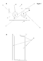
- Magnetic switches (8) and (9) are discrete.
- the first one (8) is installed to the outer construction(shutter) that closes a window and it is connected only to terminal (14).
- Respectively switch (9) which is installed to the inner construction which carries the glass is connected to the terminal (15).
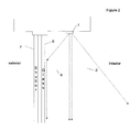
- the switch (10) is one or more magnetic switches connected in parallel with the port (25).
- the main program runs (37) the permissible status of the switch is open.
- the microprossecor causes an alarm.
- the fig 4 A presents two different ways of installing the magnetic switch (10), which may coexist if one installs two magnetic switches connected in parallel with the port (25).
- the switch (10) is placed in proximity to the switch (9),in such a distance that is not affected by the field of the magnet.
- a burglar with simple means such as a compass, could detect the location of bogie magnet switch (9) and therefore the switch itself.
- Administering a strong magnetic field from the outside of the home will take the switch (9) out of order, but it will cause the closure of switch(10) and thus cause an alarm.
- switch (10) and magnet (27) are to place them in such a relationship in order that during the opening of the closed construction, they will come into close proximity and the originally open switch (10) will close and cause an alarm.
- the arrow indicates the course of the opening. So even if someone succeeds in disabling switches (8) and (9), as the door/window opens the switch (10) will inevitably detect the magnet (27) and the alarm will go off.
- the advantages of using this method is that unlike the switches (8) and (9), the switch (10) is not detected from the exterior and it is protected by the motion detector (18). Alternatively instead of a reed switch, a hall effect sensor can be used too.
- the relay (20) is connected in series to the terminals that accept the wires of the zone, in a normally open (N.O.) condition. So when the device is not powered, the zone (13) of the control center is opened. When the processor (23) closes the relay (20) and therefore the zone (13), with energy expenditure, it holds them closed until there is a condition that breeds an alarm. In this case the signal to relay (20)comes to zero and it returns to its original normally open status opening the zone (13) of the control center.
- the operating principle of device as shown in the drawing 4B is the following: the microprocessor (23) which controls the relay (20), opens the zone (13) of the control center (11) thus causing alarm.
- the microprocessor (23) is equipped with software that allows the user to select the appropriate function of the device that best meets his/her needs by changing the settings of the jumpers (21).
- Each program requires different conditions to cause alarm (opening zone by the relay) and therefore provides the user with different permissions and therefore of a different' quality 'or 'level' of protection.
- Each program may use a different number of sensors (one, two, or even any) as well as different number of peripherals (one or two magnetic switches, with or without sensor for magnetic fields).
- the final number of rights and protection parameters e.g. glass protection, protection against magnetic fields
- the final number of rights and protection parameters e.g. glass protection, protection against magnetic fields
- FIG 5A a variation of the device is displayed that targets to more demanding users. It can be installed as a peripheral device in control centers which support dual end of line resistor (dual end-of-line resistor, DEOL). As it is described below, this device variant has two relays and enables users to modify the conditions causing alarm, of all the peripheral devices that are installed in home, by handling the keyboard of the control center.
- the operating principle of the DEOL resistance is shown in draft 5. So far, the aim of this circuit was the omission of cabling for the device's tamper, resulting in a saving of time and materials during the installation of an alarm system. Opening the switch 1 ( fig 5 B) implies a violation of the tamper.
- the relay (20) binds only in a normally open condition, while the relay (29) can be connected in both ways, N.O. and N.C..
- the existence of the relay (20) does not preclude the tamper switch (16) which can be connected in series.
- the conditions under which the relay (20) or the relay (29) are opened/closed, are programmed in the microprocessor, again with different subroutines which can be defined by the user. So potential scenarios that can occur are the following: 1) relay (29)opens each time a door is opened despite the triggering of the motion sensors, while the relay (20) is opened only when a door/window is opened from the exterior of the home or when there is an excitation firstly of the detector (18) and then of the detector (17).
- the device has a slot (30) for re-programming.
- This enables the demanding user or the installer, to design his own solution to protect an opening, which will be implemented by the developers of the company which will manage the invention. Due to the existence of this slot (30), on site programming can be made in case the current program/subroutines do not meet the user's desirable level of protection.
- the daily selection of alarm conditions is made from the keyboard of the central alarm system by enabling or disabling the tamper protection and the arming or disarming the system.
- this option offers unlimited flexibility, which makes the device able to adapt to the wishes of the residents regarding the conditions causing alarm when the system is armed or when not. Furthermore , there is a port (31) for connecting two devices together. The interface is required in cases of large openings as in the drawing 5C. In this case the installation of the devices varies in the extent that only one of the two devices is connected to the control center (11), while the two devices are linked with cables (32).
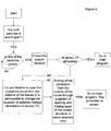
- Drawing 6 displays in the form of a flow chart the main program of the device that is common in any setting of the jumpers.
- the switches' condition is checked (initial control) (33).
- Compulsory conditions for the continuation are a) at least one of the two magnetic switches located on the window glass (9) and the shutter (8) is closed (34) and b)switch (10) does not detect a magnetic field (35). These conditions ensure that the door or window is closed and that the installation of the device's magnetic field sensor (10) was not placed in proximity to the magnetic switches (8), (9)so as to detect the fields of the coupled magnets and is therefore ineffective.
- the relay (20) does not close the zone (13) and thus a fault zone is displayed on the keypad of the control center. If both conditions are met the relay closes the zone (36) and the device goes to the main function (37).
- the microcontroller then stores (38) the condition of magnetic switches (8) and (9) and then keep comparing it with the current one(39). Any change will bring an alarm. Alarm goes off also if the switch (10) is found closed. Having established that there is no alarm treaty from the magnetic switches the system checks the motion sensors and if there is an excitation (40),it calls the subroutines that has been preselected by the user by adjusting the jumper's settings (21). Indicatively, some of the subroutines are analyzed in the following paragraphs.
- alarm can occur either by changing the state of switches or by certain patterns of motion sensors stimulation.
- the conditions causing alarm by motion sensors are: a) stimulation of the sensor (18) with a duration above a predetermined value, and b) Sequential stimulation of the first sensor (18) regardless of its duration and then of the sensor (17).
- FIG. 7 This drawing shows the way in which the microcontroller processes the signals received by the two motion sensors in order to detect the presence of alarm conditions (eg breakage of glass or breach of the shutter).
- This subroutine is called since at least one of the two structures are closed and the state of the switches is the same as the saved one . Alternatively it can be called only when the glass is closed.
- the sensor (17) is used so that no false alarm occurs whenever a tenant is approaching the door/window from the interior of the house. Under certain conditions both sensors can cause an alarm. Of the two, however, only (17) can inhibit the alarm caused by sensor(18). So starting from where the two sensors are initially inactive and sensor (18) stimulation occurs which lasts over a predetermined time (41), an alarm is caused.
- the device continues its operation with the main program (37). If immediately after stimulation of sensor (18), sensor (17) is activated, the alarm goes off(43) regardless the duration of the stimulation of sensor (18).
- the stimulation (44) of the motion detector (17) when preceding the stimulation of sensor (18) inhibits the alarm. It also inhibits the alarm caused by the change of state (45) of the magnetic switches (8,9,10).
- the detector (17) causes an alarm, only when its stimulation follows the stimulation of sensor(18).
- This way of protecting the glass through two motion sensors which inhibit or confirm each other depending on their exciting sequences, is innovative and highly reliable in its operation, because it does not give false alarms and it does not fail to detect the movement of the human body in such a short distance from the devise's detectors.
- this invention is a system for detecting human body movement (since infrared detectors are designed to be stimulated by the body temperature) and is therefore fully specialized to detect the violation.
- FIG 8 This subroutine assigns more rights to the user.
- the alteration lies at the point (46) of the chart. Stimulation of the detector (17) allows the user not only to approach the door/window but it gives him the right to change the status of the switches and even leave them both open (47). In other words, it entitles him to open the closed construction and leave it open.
- the microcontroller (23) holds the relay (20) closed and so no alarm is triggering from the control center.
- a variation can be referred to, as the change of the status of switches should be allowed to follow a specific sequence (48) which suggests motion from the inside of the house to the outside. Therefore the window glass (6) should be opened first and then the shutter (7).
- the first subroutine can be used in door/windows which are opened by an electrical mechanism, while the second can be used for the simple ones that are opened by the tenant.
- the device goes into a standby mode while keeping the zone closed.
- at least one of the two switches (8), (9) is closed, it continues the execution of the main program (37). In practice this means that with the central system being armed, the tenant is allowed to approach a door (from the interior), open the glass or /and the shutter and then close them again in any combination or leave them open for long as he wishes.
- FIG 9 As far as the implementing protection is cocerned, dr. 9 is the same with dr. 8 except that an additional right is granted.
- the user while stepping out of a door, may close the opening behind him.
- the device awaits the closed construction to be opened from the outside of the house (49). If the tenant is leaving home and he wants to activate the protection with him being outside of the house, he can perform a particular pattern of opening and closing of the closed structure (open and then close within a few sec). After this handling any attempt to open the door from the outside of the house will cause an alarm.
- the device should be powered from the control center's terminals that give power only when the alarm system is armed. So when arming the central system, the devices that monitor open door/windows, will give a fault zone signal to the alarm keypad.
- FIG. 10 This subroutine demands 2 conditions in order to be called :a) Switches (8) and (9) is open and b) the tenant must push the button on the surface of the device or alternatively close the switch (10) when opening the door/window while the sensor (17) is triggered.
- Another way to start the subroutine is to detect a specific pattern of an open-close movement of the closed structure (open-closed-open of the door/window in specific time). By using this pattern the window or the door are used as function buttons of the device.
- the system detects whether a passage from the outside to the inside of the house has happened and in that case the alarm sounds.
- the scenario covered by this drawing is as follows:
- the tenant intending to renew the air of the house, opens the doors or the window closes and reopens it to the desired range.
- Figure 11 shows another function of the devise that provides security even when the doors are completely open and the tenant can pass freely to the outside and inside of his home.
- the initial choice of the function is made by the jumpers settings and it is called at the point 47 of the drawing 8.
- Each time the device detects conditions of a passage to the exterior of the house adds a value of 1 to a variable X, whose starting value is 0.
- the value of X is checked. If it is found less than 0 the alarm goes off. The subroutine continues until one of the switches (8) and (9) is closed.
- Figure 12 describes an operation without the use of infrared detectors. In this case fewer protections exist (not glass protection) as well as fewer rights (the user can not open both structures ,glass and shutter or either one if the other is already open).
- This chart shows the function of a more economic version of the device, without the motion detectors. This device provides the sole right to open the window glass when the shutter is closed. It also protects itself from external magnetic fields and from malicious short circuit
Landscapes
- Physics & Mathematics (AREA)
- General Physics & Mathematics (AREA)
- Business, Economics & Management (AREA)
- Emergency Management (AREA)
- Engineering & Computer Science (AREA)
- Computer Security & Cryptography (AREA)
- Burglar Alarm Systems (AREA)
Applications Claiming Priority (1)
| Application Number | Priority Date | Filing Date | Title |
|---|---|---|---|
| GR20100100257A GR20100100257A (el) | 2010-05-03 | 2010-05-03 | Περιφερειακη συσκευη που συνδεεται σε οικιακα συστηματα συναγερμου και που στοχευει στην συνολικη προστασια ενος ανοιγματος μεσω μαγνητικων διακοπτων και αισθητηρων κινησης |
Publications (3)
| Publication Number | Publication Date |
|---|---|
| EP2393071A2 true EP2393071A2 (fr) | 2011-12-07 |
| EP2393071A3 EP2393071A3 (fr) | 2012-01-11 |
| EP2393071B1 EP2393071B1 (fr) | 2013-05-01 |
Family
ID=44840489
Family Applications (1)
| Application Number | Title | Priority Date | Filing Date |
|---|---|---|---|
| EP20110386009 Not-in-force EP2393071B1 (fr) | 2010-05-03 | 2011-05-02 | Dispositif périphérique qui connecte des systèmes d'alarme de domicile qui sert de protection globale d'une ouverture au moyen de commutateurs magnétiques et de capteurs de mouvement |
Country Status (2)
| Country | Link |
|---|---|
| EP (1) | EP2393071B1 (fr) |
| GR (1) | GR20100100257A (fr) |
Cited By (8)
| Publication number | Priority date | Publication date | Assignee | Title |
|---|---|---|---|---|
| WO2016109335A1 (fr) * | 2014-12-30 | 2016-07-07 | Google Inc. | Systèmes et procédés de détection d'intrusion |
| US9501924B2 (en) | 2014-12-30 | 2016-11-22 | Google Inc. | Home security system with automatic context-sensitive transition to different modes |
| US9613524B1 (en) * | 2016-04-27 | 2017-04-04 | Ecolink Intelligent Technologies, Inc. | Reduced false alarm security system |
| EP3082115A3 (fr) * | 2015-04-08 | 2017-04-26 | Google, Inc. | Rétroaction d'installation guidée pour un capteur d'ouverture |
| US10115297B2 (en) | 2015-03-27 | 2018-10-30 | Google Llc | Configuring a smart home controller |
| RU188798U1 (ru) * | 2018-10-15 | 2019-04-23 | Общество с ограниченной ответственностью "ЕХ-ПРИБОР" | Извещатель охранный магнитоконтактный взрывозащищенный |
| EP3514773A3 (fr) * | 2018-01-18 | 2019-10-30 | Ademco Inc. | Systèmes et procédés de protection d'une zone contournée dans un système de sécurité ou un système domestique connecté |
| CN110658735A (zh) * | 2019-10-29 | 2020-01-07 | 北京金山云网络技术有限公司 | 智能家居装置及系统 |
Families Citing this family (3)
| Publication number | Priority date | Publication date | Assignee | Title |
|---|---|---|---|---|
| US9945574B1 (en) | 2015-03-31 | 2018-04-17 | Google Llc | Devices and methods for setting the configuration of a smart home controller based on air pressure data |
| US9396599B1 (en) | 2015-05-29 | 2016-07-19 | Google Inc. | Systems and methods for anticipatory locking and unlocking of a smart-sensor door lock |
| GR1010375B (el) * | 2021-01-11 | 2023-01-17 | Κυριακος Αντωνιου Βουκαλης | Συστημα διαχειρισης μαγνητικων επαφων |
Citations (1)
| Publication number | Priority date | Publication date | Assignee | Title |
|---|---|---|---|---|
| JPH02170298A (ja) | 1988-12-23 | 1990-07-02 | Hiromichi Namikoshi | 侵入警報装置 |
Family Cites Families (5)
| Publication number | Priority date | Publication date | Assignee | Title |
|---|---|---|---|---|
| US4359721A (en) * | 1978-10-16 | 1982-11-16 | American District Telegraph Company | Two-wire multi-zone alarm system |
| DE3744399C2 (de) * | 1987-12-29 | 1997-03-13 | Asea Brown Boveri | Strahlungsempfindlicher Schalter |
| GB9402500D0 (en) * | 1994-02-09 | 1994-03-30 | Mccracken James | Security system |
| US5777551A (en) * | 1994-09-09 | 1998-07-07 | Hess; Brian K. | Portable alarm system |
| JP4092438B2 (ja) * | 1999-08-19 | 2008-05-28 | オプテックス株式会社 | 侵入検知方法および装置 |
-
2010
- 2010-05-03 GR GR20100100257A patent/GR20100100257A/el unknown
-
2011
- 2011-05-02 EP EP20110386009 patent/EP2393071B1/fr not_active Not-in-force
Patent Citations (1)
| Publication number | Priority date | Publication date | Assignee | Title |
|---|---|---|---|---|
| JPH02170298A (ja) | 1988-12-23 | 1990-07-02 | Hiromichi Namikoshi | 侵入警報装置 |
Cited By (20)
| Publication number | Priority date | Publication date | Assignee | Title |
|---|---|---|---|---|
| US10339773B2 (en) | 2014-12-30 | 2019-07-02 | Google Llc | Home security system with automatic context-sensitive transition to different modes |
| US9501924B2 (en) | 2014-12-30 | 2016-11-22 | Google Inc. | Home security system with automatic context-sensitive transition to different modes |
| US9558639B2 (en) | 2014-12-30 | 2017-01-31 | Google Inc. | Systems and methods of intrusion detection |
| EP3241195B1 (fr) * | 2014-12-30 | 2021-10-13 | Google LLC | Systèmes et procédés de détection d'intrusion |
| WO2016109335A1 (fr) * | 2014-12-30 | 2016-07-07 | Google Inc. | Systèmes et procédés de détection d'intrusion |
| US9672705B2 (en) | 2014-12-30 | 2017-06-06 | Google Inc. | Systems and methods of intrusion detection |
| US10115297B2 (en) | 2015-03-27 | 2018-10-30 | Google Llc | Configuring a smart home controller |
| US11967222B2 (en) | 2015-03-27 | 2024-04-23 | Google Llc | Configuring a smart home controller |
| US10559192B2 (en) | 2015-03-27 | 2020-02-11 | Google Llc | Configuring a smart home controller |
| US10401138B2 (en) | 2015-04-08 | 2019-09-03 | Google Llc | Guided installation feedback for an opening sensor |
| EP3082115A3 (fr) * | 2015-04-08 | 2017-04-26 | Google, Inc. | Rétroaction d'installation guidée pour un capteur d'ouverture |
| US9952029B2 (en) | 2015-04-08 | 2018-04-24 | Google Llc | Guided installation feedback for an opening sensor |
| US10210748B2 (en) | 2016-04-27 | 2019-02-19 | Ecolink Intelligent Technology, Inc. | Reduced false alarm security system |
| US10854069B2 (en) | 2016-04-27 | 2020-12-01 | Ecolink Intelligent Technology, Inc. | Reduced false alarm security system |
| US9613524B1 (en) * | 2016-04-27 | 2017-04-04 | Ecolink Intelligent Technologies, Inc. | Reduced false alarm security system |
| US11631320B2 (en) | 2016-04-27 | 2023-04-18 | Ecolink Intelligent Technology, Inc. | Reduced false alarm security system |
| US12027036B2 (en) | 2016-04-27 | 2024-07-02 | Ecolink Intelligent Technology, Inc. | Reduced false alarm security system |
| EP3514773A3 (fr) * | 2018-01-18 | 2019-10-30 | Ademco Inc. | Systèmes et procédés de protection d'une zone contournée dans un système de sécurité ou un système domestique connecté |
| RU188798U1 (ru) * | 2018-10-15 | 2019-04-23 | Общество с ограниченной ответственностью "ЕХ-ПРИБОР" | Извещатель охранный магнитоконтактный взрывозащищенный |
| CN110658735A (zh) * | 2019-10-29 | 2020-01-07 | 北京金山云网络技术有限公司 | 智能家居装置及系统 |
Also Published As
| Publication number | Publication date |
|---|---|
| EP2393071B1 (fr) | 2013-05-01 |
| GR20100100257A (el) | 2012-01-17 |
| EP2393071A3 (fr) | 2012-01-11 |
Similar Documents
| Publication | Publication Date | Title |
|---|---|---|
| EP2393071B1 (fr) | Dispositif périphérique qui connecte des systèmes d'alarme de domicile qui sert de protection globale d'une ouverture au moyen de commutateurs magnétiques et de capteurs de mouvement | |
| US7965171B2 (en) | Security system entry control | |
| CA2529642C (fr) | Dispositif de securite pour porte destine a des systemes de securite | |
| US6225903B1 (en) | Alarm system armed and disarmed by a deadbolt on a door | |
| EP1713045B1 (fr) | Procédé et appareil permettant de décider de l'émission d'un signal d'alarme dans un système de sécurité | |
| ES2317137T3 (es) | Metodo de programar paneles de control de seguridad para compatibilidad con un dispositivo de entrada por puerta. | |
| US6249225B1 (en) | Auxiliary alert process and system thereof for alarm system | |
| HK1214394A1 (zh) | 位置监测装置 | |
| US4271405A (en) | Alarm control system | |
| JPH02155095A (ja) | ドアデッドボルトインタロック式安全システム | |
| JPS5843097A (ja) | 複数のアクセスレベルを有する警備システム | |
| EP2779119B1 (fr) | Systèmes de contrôle d'accès avec un niveau de menace variable | |
| US7319391B2 (en) | Centralised security closure | |
| CN220491391U (zh) | 一种家庭安全监控设防报警系统 | |
| EP2613299B1 (fr) | Système d'alarme pour fenêtres et portes | |
| KR101039422B1 (ko) | 무인 경비용 개집 및 개집을 이용한 무인 경비 시스템 | |
| CA2383407C (fr) | Systeme d'alarme arme et desmarme par pene dormant d'une porte | |
| JP2005030176A (ja) | 状態の認識による分類及び認証方法と、扉監視装置。 | |
| JPH057679Y2 (fr) | ||
| KR20010069310A (ko) | 도난방지용 방범 창과 문 | |
| GB2208558A (en) | Security system | |
| RU106014U1 (ru) | Система охранной сигнализации двери | |
| JPS61187095A (ja) | 侵入警報装置 | |
| JP2005023606A (ja) | 窓戸開放制限システム | |
| JP2012036710A (ja) | 自動ドアの防犯装置 |
Legal Events
| Date | Code | Title | Description |
|---|---|---|---|
| AK | Designated contracting states |
Kind code of ref document: A2 Designated state(s): AL AT BE BG CH CY CZ DE DK EE ES FI FR GB GR HR HU IE IS IT LI LT LU LV MC MK MT NL NO PL PT RO RS SE SI SK SM TR |
|
| AX | Request for extension of the european patent |
Extension state: BA ME |
|
| PUAI | Public reference made under article 153(3) epc to a published international application that has entered the european phase |
Free format text: ORIGINAL CODE: 0009012 |
|
| PUAL | Search report despatched |
Free format text: ORIGINAL CODE: 0009013 |
|
| AK | Designated contracting states |
Kind code of ref document: A3 Designated state(s): AL AT BE BG CH CY CZ DE DK EE ES FI FR GB GR HR HU IE IS IT LI LT LU LV MC MK MT NL NO PL PT RO RS SE SI SK SM TR |
|
| AX | Request for extension of the european patent |
Extension state: BA ME |
|
| RIC1 | Information provided on ipc code assigned before grant |
Ipc: G08B 13/08 20060101AFI20111206BHEP Ipc: G08B 13/22 20060101ALN20111206BHEP Ipc: G08B 29/18 20060101ALN20111206BHEP Ipc: G08B 25/01 20060101ALI20111206BHEP |
|
| 17P | Request for examination filed |
Effective date: 20120605 |
|
| R17P | Request for examination filed (corrected) |
Effective date: 20120605 |
|
| GRAP | Despatch of communication of intention to grant a patent |
Free format text: ORIGINAL CODE: EPIDOSNIGR1 |
|
| RIC1 | Information provided on ipc code assigned before grant |
Ipc: G08B 25/00 20060101ALI20121126BHEP Ipc: G08B 13/22 20060101ALN20121126BHEP Ipc: G08B 13/08 20060101AFI20121126BHEP Ipc: G08B 25/01 20060101ALI20121126BHEP Ipc: G08B 29/18 20060101ALN20121126BHEP |
|
| GRAS | Grant fee paid |
Free format text: ORIGINAL CODE: EPIDOSNIGR3 |
|
| GRAA | (expected) grant |
Free format text: ORIGINAL CODE: 0009210 |
|
| AK | Designated contracting states |
Kind code of ref document: B1 Designated state(s): AL AT BE BG CH CY CZ DE DK EE ES FI FR GB GR HR HU IE IS IT LI LT LU LV MC MK MT NL NO PL PT RO RS SE SI SK SM TR |
|
| REG | Reference to a national code |
Ref country code: GB Ref legal event code: FG4D |
|
| REG | Reference to a national code |
Ref country code: AT Ref legal event code: REF Ref document number: 610352 Country of ref document: AT Kind code of ref document: T Effective date: 20130515 Ref country code: CH Ref legal event code: EP |
|
| REG | Reference to a national code |
Ref country code: IE Ref legal event code: FG4D |
|
| REG | Reference to a national code |
Ref country code: DE Ref legal event code: R096 Ref document number: 602011001556 Country of ref document: DE Effective date: 20130627 |
|
| REG | Reference to a national code |
Ref country code: AT Ref legal event code: MK05 Ref document number: 610352 Country of ref document: AT Kind code of ref document: T Effective date: 20130501 |
|
| REG | Reference to a national code |
Ref country code: NL Ref legal event code: VDEP Effective date: 20130501 |
|
| REG | Reference to a national code |
Ref country code: LT Ref legal event code: MG4D |
|
| PG25 | Lapsed in a contracting state [announced via postgrant information from national office to epo] |
Ref country code: PT Free format text: LAPSE BECAUSE OF FAILURE TO SUBMIT A TRANSLATION OF THE DESCRIPTION OR TO PAY THE FEE WITHIN THE PRESCRIBED TIME-LIMIT Effective date: 20130902 Ref country code: IS Free format text: LAPSE BECAUSE OF FAILURE TO SUBMIT A TRANSLATION OF THE DESCRIPTION OR TO PAY THE FEE WITHIN THE PRESCRIBED TIME-LIMIT Effective date: 20130901 Ref country code: AT Free format text: LAPSE BECAUSE OF FAILURE TO SUBMIT A TRANSLATION OF THE DESCRIPTION OR TO PAY THE FEE WITHIN THE PRESCRIBED TIME-LIMIT Effective date: 20130501 Ref country code: SE Free format text: LAPSE BECAUSE OF FAILURE TO SUBMIT A TRANSLATION OF THE DESCRIPTION OR TO PAY THE FEE WITHIN THE PRESCRIBED TIME-LIMIT Effective date: 20130501 Ref country code: NO Free format text: LAPSE BECAUSE OF FAILURE TO SUBMIT A TRANSLATION OF THE DESCRIPTION OR TO PAY THE FEE WITHIN THE PRESCRIBED TIME-LIMIT Effective date: 20130801 Ref country code: LT Free format text: LAPSE BECAUSE OF FAILURE TO SUBMIT A TRANSLATION OF THE DESCRIPTION OR TO PAY THE FEE WITHIN THE PRESCRIBED TIME-LIMIT Effective date: 20130501 Ref country code: ES Free format text: LAPSE BECAUSE OF FAILURE TO SUBMIT A TRANSLATION OF THE DESCRIPTION OR TO PAY THE FEE WITHIN THE PRESCRIBED TIME-LIMIT Effective date: 20130812 Ref country code: SI Free format text: LAPSE BECAUSE OF FAILURE TO SUBMIT A TRANSLATION OF THE DESCRIPTION OR TO PAY THE FEE WITHIN THE PRESCRIBED TIME-LIMIT Effective date: 20130501 Ref country code: GR Free format text: LAPSE BECAUSE OF FAILURE TO SUBMIT A TRANSLATION OF THE DESCRIPTION OR TO PAY THE FEE WITHIN THE PRESCRIBED TIME-LIMIT Effective date: 20130802 Ref country code: FI Free format text: LAPSE BECAUSE OF FAILURE TO SUBMIT A TRANSLATION OF THE DESCRIPTION OR TO PAY THE FEE WITHIN THE PRESCRIBED TIME-LIMIT Effective date: 20130501 |
|
| PG25 | Lapsed in a contracting state [announced via postgrant information from national office to epo] |
Ref country code: PL Free format text: LAPSE BECAUSE OF FAILURE TO SUBMIT A TRANSLATION OF THE DESCRIPTION OR TO PAY THE FEE WITHIN THE PRESCRIBED TIME-LIMIT Effective date: 20130501 Ref country code: BG Free format text: LAPSE BECAUSE OF FAILURE TO SUBMIT A TRANSLATION OF THE DESCRIPTION OR TO PAY THE FEE WITHIN THE PRESCRIBED TIME-LIMIT Effective date: 20130801 Ref country code: RS Free format text: LAPSE BECAUSE OF FAILURE TO SUBMIT A TRANSLATION OF THE DESCRIPTION OR TO PAY THE FEE WITHIN THE PRESCRIBED TIME-LIMIT Effective date: 20130501 Ref country code: HR Free format text: LAPSE BECAUSE OF FAILURE TO SUBMIT A TRANSLATION OF THE DESCRIPTION OR TO PAY THE FEE WITHIN THE PRESCRIBED TIME-LIMIT Effective date: 20130501 Ref country code: CY Free format text: LAPSE BECAUSE OF FAILURE TO SUBMIT A TRANSLATION OF THE DESCRIPTION OR TO PAY THE FEE WITHIN THE PRESCRIBED TIME-LIMIT Effective date: 20130501 |
|
| PG25 | Lapsed in a contracting state [announced via postgrant information from national office to epo] |
Ref country code: LV Free format text: LAPSE BECAUSE OF FAILURE TO SUBMIT A TRANSLATION OF THE DESCRIPTION OR TO PAY THE FEE WITHIN THE PRESCRIBED TIME-LIMIT Effective date: 20130501 |
|
| PG25 | Lapsed in a contracting state [announced via postgrant information from national office to epo] |
Ref country code: DK Free format text: LAPSE BECAUSE OF FAILURE TO SUBMIT A TRANSLATION OF THE DESCRIPTION OR TO PAY THE FEE WITHIN THE PRESCRIBED TIME-LIMIT Effective date: 20130501 Ref country code: EE Free format text: LAPSE BECAUSE OF FAILURE TO SUBMIT A TRANSLATION OF THE DESCRIPTION OR TO PAY THE FEE WITHIN THE PRESCRIBED TIME-LIMIT Effective date: 20130501 Ref country code: MC Free format text: LAPSE BECAUSE OF FAILURE TO SUBMIT A TRANSLATION OF THE DESCRIPTION OR TO PAY THE FEE WITHIN THE PRESCRIBED TIME-LIMIT Effective date: 20130501 Ref country code: CZ Free format text: LAPSE BECAUSE OF FAILURE TO SUBMIT A TRANSLATION OF THE DESCRIPTION OR TO PAY THE FEE WITHIN THE PRESCRIBED TIME-LIMIT Effective date: 20130501 Ref country code: SK Free format text: LAPSE BECAUSE OF FAILURE TO SUBMIT A TRANSLATION OF THE DESCRIPTION OR TO PAY THE FEE WITHIN THE PRESCRIBED TIME-LIMIT Effective date: 20130501 Ref country code: BE Free format text: LAPSE BECAUSE OF FAILURE TO SUBMIT A TRANSLATION OF THE DESCRIPTION OR TO PAY THE FEE WITHIN THE PRESCRIBED TIME-LIMIT Effective date: 20130501 |
|
| REG | Reference to a national code |
Ref country code: IE Ref legal event code: MM4A |
|
| PG25 | Lapsed in a contracting state [announced via postgrant information from national office to epo] |
Ref country code: RO Free format text: LAPSE BECAUSE OF FAILURE TO SUBMIT A TRANSLATION OF THE DESCRIPTION OR TO PAY THE FEE WITHIN THE PRESCRIBED TIME-LIMIT Effective date: 20130501 Ref country code: NL Free format text: LAPSE BECAUSE OF FAILURE TO SUBMIT A TRANSLATION OF THE DESCRIPTION OR TO PAY THE FEE WITHIN THE PRESCRIBED TIME-LIMIT Effective date: 20130501 Ref country code: IT Free format text: LAPSE BECAUSE OF FAILURE TO SUBMIT A TRANSLATION OF THE DESCRIPTION OR TO PAY THE FEE WITHIN THE PRESCRIBED TIME-LIMIT Effective date: 20130501 |
|
| PGFP | Annual fee paid to national office [announced via postgrant information from national office to epo] |
Ref country code: FR Payment date: 20131127 Year of fee payment: 3 |
|
| PLBE | No opposition filed within time limit |
Free format text: ORIGINAL CODE: 0009261 |
|
| STAA | Information on the status of an ep patent application or granted ep patent |
Free format text: STATUS: NO OPPOSITION FILED WITHIN TIME LIMIT |
|
| 26N | No opposition filed |
Effective date: 20140204 |
|
| PG25 | Lapsed in a contracting state [announced via postgrant information from national office to epo] |
Ref country code: IE Free format text: LAPSE BECAUSE OF NON-PAYMENT OF DUE FEES Effective date: 20130502 |
|
| REG | Reference to a national code |
Ref country code: DE Ref legal event code: R097 Ref document number: 602011001556 Country of ref document: DE Effective date: 20140204 |
|
| PGFP | Annual fee paid to national office [announced via postgrant information from national office to epo] |
Ref country code: DE Payment date: 20131127 Year of fee payment: 3 |
|
| REG | Reference to a national code |
Ref country code: DE Ref legal event code: R119 Ref document number: 602011001556 Country of ref document: DE |
|
| REG | Reference to a national code |
Ref country code: CH Ref legal event code: PL |
|
| PG25 | Lapsed in a contracting state [announced via postgrant information from national office to epo] |
Ref country code: CH Free format text: LAPSE BECAUSE OF NON-PAYMENT OF DUE FEES Effective date: 20140531 Ref country code: LI Free format text: LAPSE BECAUSE OF NON-PAYMENT OF DUE FEES Effective date: 20140531 |
|
| PG25 | Lapsed in a contracting state [announced via postgrant information from national office to epo] |
Ref country code: MT Free format text: LAPSE BECAUSE OF FAILURE TO SUBMIT A TRANSLATION OF THE DESCRIPTION OR TO PAY THE FEE WITHIN THE PRESCRIBED TIME-LIMIT Effective date: 20130501 |
|
| REG | Reference to a national code |
Ref country code: FR Ref legal event code: ST Effective date: 20150130 |
|
| REG | Reference to a national code |
Ref country code: DE Ref legal event code: R119 Ref document number: 602011001556 Country of ref document: DE Effective date: 20141202 |
|
| PG25 | Lapsed in a contracting state [announced via postgrant information from national office to epo] |
Ref country code: DE Free format text: LAPSE BECAUSE OF NON-PAYMENT OF DUE FEES Effective date: 20141202 |
|
| PG25 | Lapsed in a contracting state [announced via postgrant information from national office to epo] |
Ref country code: FR Free format text: LAPSE BECAUSE OF NON-PAYMENT OF DUE FEES Effective date: 20140602 Ref country code: SM Free format text: LAPSE BECAUSE OF FAILURE TO SUBMIT A TRANSLATION OF THE DESCRIPTION OR TO PAY THE FEE WITHIN THE PRESCRIBED TIME-LIMIT Effective date: 20130501 |
|
| PG25 | Lapsed in a contracting state [announced via postgrant information from national office to epo] |
Ref country code: TR Free format text: LAPSE BECAUSE OF FAILURE TO SUBMIT A TRANSLATION OF THE DESCRIPTION OR TO PAY THE FEE WITHIN THE PRESCRIBED TIME-LIMIT Effective date: 20130501 |
|
| PG25 | Lapsed in a contracting state [announced via postgrant information from national office to epo] |
Ref country code: MK Free format text: LAPSE BECAUSE OF FAILURE TO SUBMIT A TRANSLATION OF THE DESCRIPTION OR TO PAY THE FEE WITHIN THE PRESCRIBED TIME-LIMIT Effective date: 20130501 Ref country code: HU Free format text: LAPSE BECAUSE OF FAILURE TO SUBMIT A TRANSLATION OF THE DESCRIPTION OR TO PAY THE FEE WITHIN THE PRESCRIBED TIME-LIMIT; INVALID AB INITIO Effective date: 20110502 Ref country code: LU Free format text: LAPSE BECAUSE OF NON-PAYMENT OF DUE FEES Effective date: 20130502 |
|
| GBPC | Gb: european patent ceased through non-payment of renewal fee |
Effective date: 20150502 |
|
| PG25 | Lapsed in a contracting state [announced via postgrant information from national office to epo] |
Ref country code: GB Free format text: LAPSE BECAUSE OF NON-PAYMENT OF DUE FEES Effective date: 20150502 |
|
| PG25 | Lapsed in a contracting state [announced via postgrant information from national office to epo] |
Ref country code: AL Free format text: LAPSE BECAUSE OF FAILURE TO SUBMIT A TRANSLATION OF THE DESCRIPTION OR TO PAY THE FEE WITHIN THE PRESCRIBED TIME-LIMIT Effective date: 20130501 |