EP2393103A2 - Röntgenstrahlerzeuger sowie dessen Verwendung in einem Röntgenuntersuchungs- oder Röntgenprüfgerät - Google Patents
Röntgenstrahlerzeuger sowie dessen Verwendung in einem Röntgenuntersuchungs- oder Röntgenprüfgerät Download PDFInfo
- Publication number
- EP2393103A2 EP2393103A2 EP11006148A EP11006148A EP2393103A2 EP 2393103 A2 EP2393103 A2 EP 2393103A2 EP 11006148 A EP11006148 A EP 11006148A EP 11006148 A EP11006148 A EP 11006148A EP 2393103 A2 EP2393103 A2 EP 2393103A2
- Authority
- EP
- European Patent Office
- Prior art keywords
- housing
- ceramic
- ray
- ray generator
- tube body
- Prior art date
- Legal status (The legal status is an assumption and is not a legal conclusion. Google has not performed a legal analysis and makes no representation as to the accuracy of the status listed.)
- Granted
Links
Images
Classifications
-
- H—ELECTRICITY
- H01—ELECTRIC ELEMENTS
- H01J—ELECTRIC DISCHARGE TUBES OR DISCHARGE LAMPS
- H01J35/00—X-ray tubes
- H01J35/02—Details
- H01J35/16—Vessels; Containers; Shields associated therewith
-
- C—CHEMISTRY; METALLURGY
- C04—CEMENTS; CONCRETE; ARTIFICIAL STONE; CERAMICS; REFRACTORIES
- C04B—LIME, MAGNESIA; SLAG; CEMENTS; COMPOSITIONS THEREOF, e.g. MORTARS, CONCRETE OR LIKE BUILDING MATERIALS; ARTIFICIAL STONE; CERAMICS; REFRACTORIES; TREATMENT OF NATURAL STONE
- C04B37/00—Joining burned ceramic articles with other burned ceramic articles or other articles by heating
- C04B37/003—Joining burned ceramic articles with other burned ceramic articles or other articles by heating by means of an interlayer consisting of a combination of materials selected from glass, or ceramic material with metals, metal oxides or metal salts
- C04B37/006—Joining burned ceramic articles with other burned ceramic articles or other articles by heating by means of an interlayer consisting of a combination of materials selected from glass, or ceramic material with metals, metal oxides or metal salts consisting of metals or metal salts
-
- H—ELECTRICITY
- H01—ELECTRIC ELEMENTS
- H01J—ELECTRIC DISCHARGE TUBES OR DISCHARGE LAMPS
- H01J35/00—X-ray tubes
- H01J35/02—Details
- H01J35/16—Vessels; Containers; Shields associated therewith
- H01J35/18—Windows
-
- C—CHEMISTRY; METALLURGY
- C04—CEMENTS; CONCRETE; ARTIFICIAL STONE; CERAMICS; REFRACTORIES
- C04B—LIME, MAGNESIA; SLAG; CEMENTS; COMPOSITIONS THEREOF, e.g. MORTARS, CONCRETE OR LIKE BUILDING MATERIALS; ARTIFICIAL STONE; CERAMICS; REFRACTORIES; TREATMENT OF NATURAL STONE
- C04B2237/00—Aspects relating to ceramic laminates or to joining of ceramic articles with other articles by heating
- C04B2237/02—Aspects relating to interlayers, e.g. used to join ceramic articles with other articles by heating
- C04B2237/12—Metallic interlayers
-
- C—CHEMISTRY; METALLURGY
- C04—CEMENTS; CONCRETE; ARTIFICIAL STONE; CERAMICS; REFRACTORIES
- C04B—LIME, MAGNESIA; SLAG; CEMENTS; COMPOSITIONS THEREOF, e.g. MORTARS, CONCRETE OR LIKE BUILDING MATERIALS; ARTIFICIAL STONE; CERAMICS; REFRACTORIES; TREATMENT OF NATURAL STONE
- C04B2237/00—Aspects relating to ceramic laminates or to joining of ceramic articles with other articles by heating
- C04B2237/30—Composition of layers of ceramic laminates or of ceramic or metallic articles to be joined by heating, e.g. Si substrates
- C04B2237/32—Ceramic
- C04B2237/34—Oxidic
- C04B2237/343—Alumina or aluminates
-
- C—CHEMISTRY; METALLURGY
- C04—CEMENTS; CONCRETE; ARTIFICIAL STONE; CERAMICS; REFRACTORIES
- C04B—LIME, MAGNESIA; SLAG; CEMENTS; COMPOSITIONS THEREOF, e.g. MORTARS, CONCRETE OR LIKE BUILDING MATERIALS; ARTIFICIAL STONE; CERAMICS; REFRACTORIES; TREATMENT OF NATURAL STONE
- C04B2237/00—Aspects relating to ceramic laminates or to joining of ceramic articles with other articles by heating
- C04B2237/50—Processing aspects relating to ceramic laminates or to the joining of ceramic articles with other articles by heating
- C04B2237/62—Forming laminates or joined articles comprising holes, channels or other types of openings
-
- C—CHEMISTRY; METALLURGY
- C04—CEMENTS; CONCRETE; ARTIFICIAL STONE; CERAMICS; REFRACTORIES
- C04B—LIME, MAGNESIA; SLAG; CEMENTS; COMPOSITIONS THEREOF, e.g. MORTARS, CONCRETE OR LIKE BUILDING MATERIALS; ARTIFICIAL STONE; CERAMICS; REFRACTORIES; TREATMENT OF NATURAL STONE
- C04B2237/00—Aspects relating to ceramic laminates or to joining of ceramic articles with other articles by heating
- C04B2237/50—Processing aspects relating to ceramic laminates or to the joining of ceramic articles with other articles by heating
- C04B2237/76—Forming laminates or joined articles comprising at least one member in the form other than a sheet or disc, e.g. two tubes or a tube and a sheet or disc
- C04B2237/765—Forming laminates or joined articles comprising at least one member in the form other than a sheet or disc, e.g. two tubes or a tube and a sheet or disc at least one member being a tube
-
- C—CHEMISTRY; METALLURGY
- C04—CEMENTS; CONCRETE; ARTIFICIAL STONE; CERAMICS; REFRACTORIES
- C04B—LIME, MAGNESIA; SLAG; CEMENTS; COMPOSITIONS THEREOF, e.g. MORTARS, CONCRETE OR LIKE BUILDING MATERIALS; ARTIFICIAL STONE; CERAMICS; REFRACTORIES; TREATMENT OF NATURAL STONE
- C04B2237/00—Aspects relating to ceramic laminates or to joining of ceramic articles with other articles by heating
- C04B2237/50—Processing aspects relating to ceramic laminates or to the joining of ceramic articles with other articles by heating
- C04B2237/80—Joining the largest surface of one substrate with a smaller surface of the other substrate, e.g. butt joining or forming a T-joint
-
- H—ELECTRICITY
- H01—ELECTRIC ELEMENTS
- H01J—ELECTRIC DISCHARGE TUBES OR DISCHARGE LAMPS
- H01J2235/00—X-ray tubes
- H01J2235/16—Vessels
-
- H—ELECTRICITY
- H01—ELECTRIC ELEMENTS
- H01J—ELECTRIC DISCHARGE TUBES OR DISCHARGE LAMPS
- H01J2235/00—X-ray tubes
- H01J2235/18—Windows, e.g. for X-ray transmission
Definitions
- the invention relates to an X-ray generator with a tubular housing and arranged in the housing assemblies for generating one or more X-rays and its use in particular in an X-ray machine for checking luggage or the like.
- X-ray generators designated as X-ray tubes are known to have at least one anode and at least one cathode, which are arranged in an evacuated housing.
- the housing usually consists of a glass bulb or a metal cylinder, which is closed with end caps.
- An X-ray examination apparatus with such a designed X-ray source is known from DE 196 08 862 A1 known.
- An X-ray source with a glass bulb is used.
- a vacuum housing for an X-ray tube describes the DE 103 20 700 A1 , To increase the service life, a certain area of the housing is provided with a protective layer.
- the protective layer consists inter alia of a ceramic high-temperature material, which is applied by plasma spraying on the wall.
- the invention has for its object to provide an X-ray generator, which is easier, cheaper and more reproducible dimensions produced.
- the housing of the X-ray generator is formed by a tubular body, which consists of ceramic.
- the ceramic is selected to have some surface conductivity sufficient to prevent charge nests.
- the lid and the bottom of the housing are preferably also made of ceramic. They can be connected to the tube body in a simplified and safe manner by means of an active soldering method.
- the required exit window for the X-ray radiation can be advantageously incorporated as a dilute ceramic layer in the tube body, for example milling.
- the introduction of a separate window is therefore no longer necessary.
- the ceramic used should have a low thermal expansion coefficient, a high vacuum tightness, and a good surface conductivity.
- the desired surface conductivity can be achieved by doping the ceramic. A separate step to improve the conductivity, such as the application of a conductive coating is then no longer necessary.
- a suitable ceramic an alumina ceramic has shown.
- Ceramic material offers the further advantage over glass in that the dimensional accuracy with respect to the positioning of anode to cathode in all three spatial directions is improved.
- the use of an active solder to connect the individual components significantly simplifies the usual process of pre-metallizing the ceramic in the manufacture of metal or ceramic tubes. The production is thus cheaper.
- An X-ray generator according to the invention is preferably used in an X-ray examination or X-ray inspection apparatus.
- the use is preferably carried out in X-ray inspection devices for security checking of items of luggage or other objects, for example at airports.
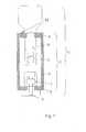
- FIG. 1 shows a section through an X-ray generator according to the invention.
- the X-ray generator 1 has a housing 2, which consists of a tubular body 3 with an approximately annular cross-section, a lid 4 and a bottom 5. In the housing 2, the known assemblies for generating one or more X-rays are arranged.
- the cathode 7 and the anode 8 are shown in the drawing.
- At least the tubular body 3 is made of ceramic, for example of an alumina ceramic. If required for sufficient surface conductivity, the ceramic is doped.
- the lid 4 and the bottom 5 are preferably also made of a suitable ceramic and connected to the tube body 3 by an active soldering method.
- the electrical leads 9 for the cathode 7 and the electrically conductive bushing 10 of the anode 8 are gas-tightly secured in the bottom 5 or in the cover 4.
- the attachment is also preferably carried out by an active soldering method.
- an exit window 6 for the X-rays is incorporated as a dilute ceramic layer.
- ceramic is removed in the corresponding area, for example milled off.
- the exit window 6 is incorporated from the inside into the tube body 3.
- the exit window 6 is then located on the inside of the tube body 3, as in FIG. 1 is shown. This has the advantage that the outside of the tube body 3 remains a continuous layer which is farther away from the anode 8 than if the window 6 were located outside. Due to the greater distance in this area, the field strength is lower, so that the risk of breakdown of electrons through the window 6 is reduced.
- FIG. 1 illustrated X-ray generator 1 used in an X-ray machine, which is used for security checking of luggage or similar items, for example, at airports.
Landscapes
- Chemical & Material Sciences (AREA)
- Engineering & Computer Science (AREA)
- Ceramic Engineering (AREA)
- Materials Engineering (AREA)
- Structural Engineering (AREA)
- Organic Chemistry (AREA)
- Analysing Materials By The Use Of Radiation (AREA)
- X-Ray Techniques (AREA)
Abstract
Description
- Die Erfindung betrifft einen Röntgenstrahlerzeuger mit einem röhrenförmigen Gehäuse und in dem Gehäuse angeordneten Baugruppen zur Erzeugung eines oder mehrerer Röntgenstrahlen sowie dessen Verwendung insbesondere in einem Röntgenprüfgerät zur Überprüfung von Gepäckstücken oder ähnlichem. Als Röntgenröhren bezeichnete Röntgenstrahlerzeuger weisen bekannterweise wenigstens eine Anode und wenigstens eine Kathode auf, die in einem evakuierten Gehäuse angeordnet sind. Das Gehäuse besteht in der Regel aus einem Glaskolben oder einem Metallzylinder, der mit Abschlussdeckeln verschlossen ist.
- Ein Röntgenuntersuchungsgerät mit einem derart gestalteten Röntgenstrahler ist aus der
DE 196 08 862 A1 bekannt. Es wird ein Röntgenstrahler mit einem Glaskolben verwendet. - In der
DE 198 02 668 A1 wird ein Röntgenstrahlerzeuger beschrieben, der eine gemeinsame Anode und zwei Kathoden aufweist (Dual-Energy-Erzeuger), die ebenfalls in einem Glaskolben untergebracht sind. - Ein Vakuumgehäuse für eine Röntgenröhre beschreibt die
DE 103 20 700 A1 . Um die Lebensdauer zu steigern, wird ein bestimmter Bereich des Gehäuses mit einer Schutzschicht versehen. Die Schutzschicht besteht dabei unter anderem aus einem keramischen Hochtemperaturwerkstoff, der durch Plasmaspritzen auf die Wandung aufgebracht wird. - Der Erfindung liegt die Aufgabe zugrunde, einen Röntgenstrahlerzeuger zu schaffen, der einfacher, kostengünstiger und mit besser reproduzierbaren Maßen herstellbar ist.
- Diese Aufgabe wird nach der Erfindung dadurch gelöst, dass das Gehäuse des Röntgenstrahlerzeugers von einem Röhrenkörper gebildet wird, der aus Keramik besteht.
- Die Keramik ist so ausgewählt, dass sie eine gewisse Oberflächenleitfähigkeit aufweist, die ausreicht um Ladungsnester zu verhindern. Der Deckel und der Boden des Gehäuses bestehen bevorzugt ebenfalls aus Keramik. Sie können vereinfacht und sicher durch ein Aktivlot-Verfahren mit dem Röhrenkörper verbunden werden.
- Das benötigte Austrittsfenster für die Röntgenstrahlung lässt sich vorteilhaft als verdünnte Keramikschicht in den Röhrenkörper einarbeiten, beispielsweise einfräsen. Das Einbringen eines gesonderten Fensters ist somit nicht mehr notwendig.
- Die verwendete Keramik sollte einen geringen Wärmeausdehnungskoeffizienten, eine hohe Vakuumdichtigkeit, sowie eine gute Oberflächenleitfähigkeit besitzen. Die gewünschte Oberflächenleitfähigkeit kann durch eine Dotierung der Keramik erreicht werden. Ein gesonderter Arbeitsschritt zur Verbesserung der Leitfähigkeit, beispielsweise das Auftragen einer leitfähigen Beschichtung, ist dann nicht mehr erforderlich. Als geeignete Keramik hat sich eine Aluminiumoxidkeramik gezeigt.
- Keramikmaterial bietet gegenüber Glas den weiteren Vorteil, dass die Maßhaltigkeit in Bezug auf die Positionierung von Anode zu Kathode in allen drei Raumrichtungen verbessert wird. Durch die Verwendung eines Aktivlotes zur Verbindung der einzelnen Komponenten wird der übliche Prozess der Vormetallisierung der Keramik bei der Fertigung von Metall- oder Keramikröhren deutlich vereinfacht. Die Herstellung ist somit kostengünstiger.
- Ein Röntgenstrahlerzeuger nach der Erfindung wird bevorzugt in einem Röntgenuntersuchungs- oder Röntgenprüfgerät eingesetzt. Bevorzugt erfolgt die Verwendung in Röntgenprüfgeräten zur Sicherheitsüberprüfung von Gepäckstücken oder anderen Gegenständen beispielsweise auf Flughäfen.
- Nachfolgend wird die Erfindung anhand eines Ausführungsbeispiels erläutert.
-
Figur 1 zeigt einen Schnitt durch einen erfindungsgemäßen Röntgenstrahlerzeuger. - Der Röntgenstrahlerzeuger 1 weist ein Gehäuse 2 auf, das aus einem Röhrenkörper 3 mit etwa ringförmigem Querschnitt, einem Deckel 4 und einem Boden 5 besteht. In dem Gehäuse 2 sind die bekannten Baugruppen zur Erzeugung eines oder mehrerer Röntgenstrahlen angeordnet. Die Kathode 7 und die Anode 8 sind in der Zeichnung dargestellt. Zumindest der Röhrenkörper 3 ist aus Keramik gefertigt, beispielsweise aus einer Aluminiumoxidkeramik. Falls für eine ausreichende Oberflächenleitfähigkeit erforderlich, ist die Keramik dotiert.
- Der Deckel 4 und der Boden 5 sind bevorzugt ebenfalls aus einer geeigneten Keramik gefertigt und mit dem Röhrenkörper 3 durch ein Aktivlot-Verfahren verbunden. Dabei sind die elektrischen Zuleitungen 9 für die Kathode 7 und die elektrisch leitende Durchführung 10 der Anode 8 gasdicht im Boden 5 beziehungsweise im Deckel 4 befestigt. Die Befestigung erfolgt ebenfalls bevorzugt durch ein Aktivlot-Verfahren.
- In den Röhrenkörper 3 ist ein Austrittsfenster 6 für die Röntgenstrahlen als verdünnte Keramikschicht eingearbeitet. Zur Verdünnung der Keramikschicht am Austrittsfenster 6 wird Keramik in dem entsprechenden Bereich abgetragen, beispielsweise abgefräst. Bevorzugt wird das Austrittsfenster 6 von innen in den Röhrenkörper 3 eingearbeitet. Das Austrittsfenster 6 befindet sich dann auf der Innenseite des Röhrenkörpers 3, wie in
Figur 1 dargestellt ist. Dies hat den Vorteil, dass außen im Röhrenkörper 3 eine durchgehende Schicht verbleibt, die weiter entfernt von der Anode 8 ist als wenn sich das Fenster 6 außen befinden würde. Aufgrund der größeren Entfernung ist in diesem Bereich die Feldstärke geringer, so dass die Gefahr eines Durchschlags von Elektronen durch das Fenster 6 verringert wird. - Bevorzugt wird der in
Figur 1 dargestellte Röntgenstrahlerzeuger 1 in einem Röntgenprüfgerät verwendet, das zur Sicherheitsüberprüfung von Gepäckstücken oder ähnlichen Gegenständen beispielsweise auf Flughäfen dient.
Claims (7)
- Röntgenstrahlerzeuger (1) mit einem Gehäuse (2) und in dem Gehäuse (2) angeordneten Baugruppen zur Erzeugung eines oder mehrerer Röntgenstrahlen, dadurch gekennzeichnet, dass das Gehäuse (2) von einem Röhrenkörper (3) gebildet wird, der aus Keramik besteht, und dass ein Austrittsfenster (6) für die Röntgenstrahlen als verdünnte Keramikschicht in den Röhrenkörper (3) eingearbeitet ist.
- Röntgenstrahlerzeuger nach Anspruch 1, dadurch gekennzeichnet, dass das Austrittsfenster (6) auf der Innenseite des Röhrenkörpers (3) in diesen eingearbeitet ist.
- Röntgenstrahlerzeuger (1) mit einem Gehäuse (2) und in dem Gehäuse (2) angeordneten Baugruppen zur Erzeugung eines oder mehrerer Röntgenstrahlen, dadurch gekennzeichnet, dass das Gehäuse (2) von einem Röhrenkörper (3) gebildet wird, der aus einer Keramik besteht, die für eine zur Vermeidung von Ladungsnestern ausreichende Oberflächenleitfähigkeit dotiert ist.
- Röntgenstrahlerzeuger nach einem der Ansprüche 1 bis 3, dadurch gekennzeichnet, dass das Gehäuse (2) einen Deckel (4) und einen Boden (5) enthält, die ebenfalls aus Keramik bestehen.
- Röntgenstrahlerzeuger nach Anspruch 4, dadurch gekennzeichnet, dass der Röhrenkörper (3) mit dem Deckel (4) und/oder dem Boden (5) durch ein Aktivlot-Verfahren verbunden ist.
- Röntgenstrahlerzeuger nach einem der Ansprüche 1 bis 5, dadurch gekennzeichnet, dass die verwendete Keramik eine Aluminiumoxidkeramik ist.
- Verwendung eines Röntgenstrahlerzeugers (1) gemäß einem der Ansprüche 1 bis 6 in einem Röntgenuntersuchungs- oder Röntgenprüfgerät, insbesondere zur Sicherheitsüberprüfung von Gepäckstücken oder ähnlichen Gegenständen.
Applications Claiming Priority (2)
| Application Number | Priority Date | Filing Date | Title |
|---|---|---|---|
| DE102008006620A DE102008006620A1 (de) | 2008-01-29 | 2008-01-29 | Röntgenstrahlerzeuger sowie dessen Verwendung in einem Röntgenuntersuchungs- oder Röntgenprüfgerät |
| EP08871651.9A EP2235734B1 (de) | 2008-01-29 | 2008-11-05 | Röntgenstrahlerzeuger sowie dessen verwendung in einem röntgenuntersuchungs- oder röntgenprüfgerät |
Related Parent Applications (2)
| Application Number | Title | Priority Date | Filing Date |
|---|---|---|---|
| EP08871651.9A Division EP2235734B1 (de) | 2008-01-29 | 2008-11-05 | Röntgenstrahlerzeuger sowie dessen verwendung in einem röntgenuntersuchungs- oder röntgenprüfgerät |
| EP08871651.9 Division | 2008-11-05 |
Publications (3)
| Publication Number | Publication Date |
|---|---|
| EP2393103A2 true EP2393103A2 (de) | 2011-12-07 |
| EP2393103A3 EP2393103A3 (de) | 2012-02-22 |
| EP2393103B1 EP2393103B1 (de) | 2016-01-27 |
Family
ID=40293786
Family Applications (2)
| Application Number | Title | Priority Date | Filing Date |
|---|---|---|---|
| EP11006148.8A Active EP2393103B1 (de) | 2008-01-29 | 2008-11-05 | Röntgenstrahlerzeuger sowie dessen Verwendung in einem Röntgenuntersuchungs- oder Röntgenprüfgerät |
| EP08871651.9A Active EP2235734B1 (de) | 2008-01-29 | 2008-11-05 | Röntgenstrahlerzeuger sowie dessen verwendung in einem röntgenuntersuchungs- oder röntgenprüfgerät |
Family Applications After (1)
| Application Number | Title | Priority Date | Filing Date |
|---|---|---|---|
| EP08871651.9A Active EP2235734B1 (de) | 2008-01-29 | 2008-11-05 | Röntgenstrahlerzeuger sowie dessen verwendung in einem röntgenuntersuchungs- oder röntgenprüfgerät |
Country Status (8)
| Country | Link |
|---|---|
| US (1) | US8073108B2 (de) |
| EP (2) | EP2393103B1 (de) |
| CN (1) | CN101911243B (de) |
| CA (1) | CA2711869A1 (de) |
| DE (1) | DE102008006620A1 (de) |
| ES (1) | ES2565640T3 (de) |
| RU (1) | RU2490748C2 (de) |
| WO (1) | WO2009095047A2 (de) |
Cited By (1)
| Publication number | Priority date | Publication date | Assignee | Title |
|---|---|---|---|---|
| DE102017127372A1 (de) | 2017-11-21 | 2019-05-23 | Smiths Heimann Gmbh | Anodenkopf für Röntgenstrahlenerzeuger |
Families Citing this family (6)
| Publication number | Priority date | Publication date | Assignee | Title |
|---|---|---|---|---|
| GB0816823D0 (en) * | 2008-09-13 | 2008-10-22 | Cxr Ltd | X-ray tubes |
| DE102014222164A1 (de) | 2014-10-30 | 2016-05-04 | Smiths Heimann Gmbh | Kühlkörper, insbesondere für die Anode eines Röntgenstrahlungserzeugers |
| CN106941064B (zh) * | 2017-04-25 | 2018-11-09 | 成都凯赛尔电子有限公司 | X射线管及其制造方法 |
| RU2716261C1 (ru) * | 2019-10-02 | 2020-03-11 | Акционерное общество "Обнинское научно-производственное предприятие "Технология" им. А.Г.Ромашина" | Высокоресурсная металлокерамическая рентгеновская трубка |
| RU2760320C1 (ru) * | 2021-04-13 | 2021-11-23 | Акционерное общество "Обнинское научно-производственное предприятие "Технология" им. А.Г.Ромашина" | Способ изготовления вакуумплотного бериллиевого выпускного окна |
| US11791123B2 (en) * | 2021-04-29 | 2023-10-17 | Electronics And Telecommunications Research Institute | X-ray tube |
Citations (3)
| Publication number | Priority date | Publication date | Assignee | Title |
|---|---|---|---|---|
| DE19608862A1 (de) | 1996-03-07 | 1997-09-11 | Philips Patentverwaltung | Röntgenuntersuchungsgerät mit einem Röntgenstrahler und einer damit verbundenen Blendeneinheit |
| DE19802668A1 (de) | 1998-01-24 | 1999-07-29 | Heimann Systems Gmbh & Co | Röntgenstrahlungserzeuger |
| DE10320700A1 (de) | 2003-05-08 | 2004-12-02 | Siemens Ag | Vakuumgehäuse für eine Röntgenröhre |
Family Cites Families (26)
| Publication number | Priority date | Publication date | Assignee | Title |
|---|---|---|---|---|
| NL40867C (de) * | 1933-07-21 | |||
| US3691417A (en) * | 1969-09-02 | 1972-09-12 | Watkins Johnson Co | X-ray generating assembly and system |
| DE2506841C2 (de) * | 1975-02-18 | 1986-07-03 | Philips Patentverwaltung Gmbh, 2000 Hamburg | Hochspannungs-Vakuumröhre |
| JPS5756442Y2 (de) * | 1978-06-23 | 1982-12-04 | ||
| US5111493A (en) * | 1988-11-25 | 1992-05-05 | Wisconsin Alumni Research Foundation | Portable X-ray system with ceramic tube |
| DE4308361C2 (de) * | 1993-03-16 | 1998-12-10 | Siemens Ag | Verfahren zur Herstellung einer Verbindung zweier Keramikteile bzw. eines Metall- und eines Keramikteils |
| US5627871A (en) * | 1993-06-10 | 1997-05-06 | Nanodynamics, Inc. | X-ray tube and microelectronics alignment process |
| US5854822A (en) * | 1997-07-25 | 1998-12-29 | Xrt Corp. | Miniature x-ray device having cold cathode |
| JP4334639B2 (ja) * | 1998-07-30 | 2009-09-30 | 浜松ホトニクス株式会社 | X線管 |
| US6353658B1 (en) * | 1999-09-08 | 2002-03-05 | The Regents Of The University Of California | Miniature x-ray source |
| US20030002627A1 (en) * | 2000-09-28 | 2003-01-02 | Oxford Instruments, Inc. | Cold emitter x-ray tube incorporating a nanostructured carbon film electron emitter |
| DE10048833C2 (de) * | 2000-09-29 | 2002-08-08 | Siemens Ag | Vakuumgehäuse für eine Vakuumröhre mit einem Röntgenfenster |
| IL140025A0 (en) | 2000-11-30 | 2002-02-10 | Medirad I R T Ltd | X-ray tube with fluid cooling |
| US6415016B1 (en) * | 2001-01-09 | 2002-07-02 | Medtronic Ave, Inc. | Crystal quartz insulating shell for X-ray catheter |
| DE10147473C2 (de) * | 2001-09-25 | 2003-09-25 | Siemens Ag | Drehanodenröntgenröhre |
| JP4068332B2 (ja) * | 2001-10-19 | 2008-03-26 | 浜松ホトニクス株式会社 | X線管、及び、x線管の製造方法 |
| US6570962B1 (en) * | 2002-01-30 | 2003-05-27 | Koninklijke Philips Electronics N.V. | X-ray tube envelope with integral corona shield |
| RU26685U1 (ru) * | 2002-05-21 | 2002-12-10 | Лупехин Сергей Матвеевич | Импульсная рентгеновская трубка |
| AU2002322968A1 (en) * | 2002-09-09 | 2004-03-29 | Comet Holding Ag | High-voltage vacuum tube |
| US7127034B1 (en) * | 2003-02-05 | 2006-10-24 | Varian Medical Systems Technologies, Inc. | Composite stator |
| AU2003281900A1 (en) * | 2003-12-02 | 2005-06-24 | Comet Holding Ag | Modular x-ray tube and method for the production thereof |
| DE112004002771A5 (de) * | 2004-03-02 | 2008-08-28 | Comet Holding Ag | Röntgenröhre für hohe Dosisleistungen, Verfahren zur Erzeugung von hohen Dosisleistungen mit Röntgenröhren sowie ein Verfahren zur Herstellung entsprechender Röntgenvorrichtungen |
| US7236568B2 (en) * | 2004-03-23 | 2007-06-26 | Twx, Llc | Miniature x-ray source with improved output stability and voltage standoff |
| JP4465522B2 (ja) * | 2004-07-05 | 2010-05-19 | 株式会社日立メディコ | X線管 |
| RU2278440C1 (ru) * | 2005-04-20 | 2006-06-20 | Государственное образовательное учреждение высшего профессионального образования "Санкт-Петербургский государственный электротехнический университет "ЛЭТИ" им. В.И. Ульянова (Ленина)" | Моноблок источника рентгеновского излучения |
| US7382862B2 (en) * | 2005-09-30 | 2008-06-03 | Moxtek, Inc. | X-ray tube cathode with reduced unintended electrical field emission |
-
2008
- 2008-01-29 DE DE102008006620A patent/DE102008006620A1/de not_active Withdrawn
- 2008-11-05 EP EP11006148.8A patent/EP2393103B1/de active Active
- 2008-11-05 ES ES11006148.8T patent/ES2565640T3/es active Active
- 2008-11-05 RU RU2010135620/07A patent/RU2490748C2/ru active
- 2008-11-05 CA CA2711869A patent/CA2711869A1/en not_active Abandoned
- 2008-11-05 CN CN2008801234485A patent/CN101911243B/zh active Active
- 2008-11-05 WO PCT/EP2008/009300 patent/WO2009095047A2/de not_active Ceased
- 2008-11-05 EP EP08871651.9A patent/EP2235734B1/de active Active
-
2010
- 2010-07-28 US US12/845,229 patent/US8073108B2/en active Active
Patent Citations (3)
| Publication number | Priority date | Publication date | Assignee | Title |
|---|---|---|---|---|
| DE19608862A1 (de) | 1996-03-07 | 1997-09-11 | Philips Patentverwaltung | Röntgenuntersuchungsgerät mit einem Röntgenstrahler und einer damit verbundenen Blendeneinheit |
| DE19802668A1 (de) | 1998-01-24 | 1999-07-29 | Heimann Systems Gmbh & Co | Röntgenstrahlungserzeuger |
| DE10320700A1 (de) | 2003-05-08 | 2004-12-02 | Siemens Ag | Vakuumgehäuse für eine Röntgenröhre |
Cited By (1)
| Publication number | Priority date | Publication date | Assignee | Title |
|---|---|---|---|---|
| DE102017127372A1 (de) | 2017-11-21 | 2019-05-23 | Smiths Heimann Gmbh | Anodenkopf für Röntgenstrahlenerzeuger |
Also Published As
| Publication number | Publication date |
|---|---|
| EP2235734B1 (de) | 2013-09-04 |
| CN101911243B (zh) | 2012-05-09 |
| DE102008006620A1 (de) | 2009-08-06 |
| WO2009095047A2 (de) | 2009-08-06 |
| EP2393103A3 (de) | 2012-02-22 |
| RU2010135620A (ru) | 2012-03-10 |
| WO2009095047A3 (de) | 2009-12-30 |
| RU2490748C2 (ru) | 2013-08-20 |
| EP2235734A2 (de) | 2010-10-06 |
| EP2393103B1 (de) | 2016-01-27 |
| CA2711869A1 (en) | 2009-08-06 |
| HK1146558A1 (en) | 2011-06-17 |
| CN101911243A (zh) | 2010-12-08 |
| US20100290588A1 (en) | 2010-11-18 |
| US8073108B2 (en) | 2011-12-06 |
| ES2565640T3 (es) | 2016-04-06 |
Similar Documents
| Publication | Publication Date | Title |
|---|---|---|
| EP2393103B1 (de) | Röntgenstrahlerzeuger sowie dessen Verwendung in einem Röntgenuntersuchungs- oder Röntgenprüfgerät | |
| DE102009025841B4 (de) | Vorrichtung für einen kompakten Hochspannungsisolator für eine Röntgen- und Vakuumröhre und Verfahren zur Montage derselben | |
| EP0601595A1 (de) | Zur Anordnung in einem Vakuumgefäss geeignete selbsttragende isolierte Leiteranordnung, insbesondere Antennenspule für einen Hochfrequenz-Plasmagenerator | |
| EP3685420B1 (de) | Mbfex-röhre | |
| EP1783809A2 (de) | Nanofocus-Röntgenröhre | |
| DE102010061229A1 (de) | Vorrichtung zum Modifizieren des Elektronenstrahl-Aspektverhältnisses zur Röntgenstrahlungserzeugung | |
| DE2437774C2 (de) | Verfahren zur Herstellung einer Elektrodeneinführung für eine Hochdruck-Entladungslampe und mittels dieses Verfahrens hergestellte Elektrodeneinführungen | |
| DE102011115841A1 (de) | Bestrahlungsvorrichtung | |
| DE102008038582A1 (de) | Röntgenstrahler | |
| DE102014015974B4 (de) | Anschlusskabel zur Verminderung von überschlagsbedingten transienten elektrischen Signalen zwischen der Beschleunigungsstrecke einer Röntgenröhre sowie einer Hochspannungsquelle | |
| DE102005060242B4 (de) | Verfahren und Aufbau zur Milderung der elektrischen Beanspruchung an Hochspannungsisolatoren in Röntgenröhren | |
| EP2494577A1 (de) | Vorrichtung zum reflektieren beschleunigter elektronen | |
| DE2128255C3 (de) | Elektronenstrahlgenerator | |
| DE102014112275B4 (de) | Röntgenröhre mit Anodenelektrode | |
| DE3001983C2 (de) | ||
| WO2019101784A1 (de) | Anodenkopf für röntgenstrahlenerzeuger | |
| DE102005010716A1 (de) | Kaltkathoden-Drucksensor | |
| DE102011000271A1 (de) | Verfahren zum Herstellen einer frittefreien Abdichtung in einer keramischen Bogenröhre für eine Entladungslampe | |
| EP0458222B1 (de) | Hochspannungsdurchführung für Korpuskularstrahlgeräte | |
| DE3844814C2 (de) | ||
| DE2113976B2 (de) | Impuls-Röntgenröhre | |
| DE102010034597A1 (de) | Röntgenoptik mit Strahleneintrittsfenster und Strahlenaustrittsfenster | |
| EP2893551A1 (de) | Dielektrisch behinderte entladungs-lampe | |
| DE19914825A1 (de) | Vakuumgehäuse für eine Elektronenröhre | |
| DE1193567B (de) | Thermionischer Wandler |
Legal Events
| Date | Code | Title | Description |
|---|---|---|---|
| AC | Divisional application: reference to earlier application |
Ref document number: 2235734 Country of ref document: EP Kind code of ref document: P |
|
| AK | Designated contracting states |
Kind code of ref document: A2 Designated state(s): AT BE BG CH CY CZ DE DK EE ES FI FR GB GR HR HU IE IS IT LI LT LU LV MC MT NL NO PL PT RO SE SI SK TR |
|
| PUAI | Public reference made under article 153(3) epc to a published international application that has entered the european phase |
Free format text: ORIGINAL CODE: 0009012 |
|
| RIC1 | Information provided on ipc code assigned before grant |
Ipc: H01J 35/18 20060101ALI20111206BHEP Ipc: H01J 35/16 20060101AFI20111206BHEP |
|
| PUAL | Search report despatched |
Free format text: ORIGINAL CODE: 0009013 |
|
| AK | Designated contracting states |
Kind code of ref document: A3 Designated state(s): AT BE BG CH CY CZ DE DK EE ES FI FR GB GR HR HU IE IS IT LI LT LU LV MC MT NL NO PL PT RO SE SI SK TR |
|
| RIC1 | Information provided on ipc code assigned before grant |
Ipc: H01J 35/16 20060101AFI20120116BHEP Ipc: H01J 35/18 20060101ALI20120116BHEP |
|
| 17P | Request for examination filed |
Effective date: 20120815 |
|
| 17Q | First examination report despatched |
Effective date: 20130617 |
|
| REG | Reference to a national code |
Ref country code: DE Ref legal event code: R079 Ref document number: 502008013794 Country of ref document: DE Free format text: PREVIOUS MAIN CLASS: H01J0035160000 Ipc: C04B0037000000 |
|
| GRAP | Despatch of communication of intention to grant a patent |
Free format text: ORIGINAL CODE: EPIDOSNIGR1 |
|
| RIC1 | Information provided on ipc code assigned before grant |
Ipc: C04B 37/00 20060101AFI20150615BHEP Ipc: H01J 35/18 20060101ALI20150615BHEP Ipc: H01J 35/16 20060101ALI20150615BHEP |
|
| INTG | Intention to grant announced |
Effective date: 20150709 |
|
| GRAS | Grant fee paid |
Free format text: ORIGINAL CODE: EPIDOSNIGR3 |
|
| GRAA | (expected) grant |
Free format text: ORIGINAL CODE: 0009210 |
|
| AC | Divisional application: reference to earlier application |
Ref document number: 2235734 Country of ref document: EP Kind code of ref document: P |
|
| AK | Designated contracting states |
Kind code of ref document: B1 Designated state(s): AT BE BG CH CY CZ DE DK EE ES FI FR GB GR HR HU IE IS IT LI LT LU LV MC MT NL NO PL PT RO SE SI SK TR |
|
| REG | Reference to a national code |
Ref country code: GB Ref legal event code: FG4D Free format text: NOT ENGLISH |
|
| REG | Reference to a national code |
Ref country code: CH Ref legal event code: EP |
|
| REG | Reference to a national code |
Ref country code: AT Ref legal event code: REF Ref document number: 772607 Country of ref document: AT Kind code of ref document: T Effective date: 20160215 |
|
| REG | Reference to a national code |
Ref country code: IE Ref legal event code: FG4D Free format text: LANGUAGE OF EP DOCUMENT: GERMAN |
|
| REG | Reference to a national code |
Ref country code: DE Ref legal event code: R096 Ref document number: 502008013794 Country of ref document: DE |
|
| REG | Reference to a national code |
Ref country code: ES Ref legal event code: FG2A Ref document number: 2565640 Country of ref document: ES Kind code of ref document: T3 Effective date: 20160406 |
|
| REG | Reference to a national code |
Ref country code: LT Ref legal event code: MG4D |
|
| REG | Reference to a national code |
Ref country code: NL Ref legal event code: MP Effective date: 20160127 |
|
| PG25 | Lapsed in a contracting state [announced via postgrant information from national office to epo] |
Ref country code: NL Free format text: LAPSE BECAUSE OF FAILURE TO SUBMIT A TRANSLATION OF THE DESCRIPTION OR TO PAY THE FEE WITHIN THE PRESCRIBED TIME-LIMIT Effective date: 20160127 |
|
| PG25 | Lapsed in a contracting state [announced via postgrant information from national office to epo] |
Ref country code: GR Free format text: LAPSE BECAUSE OF FAILURE TO SUBMIT A TRANSLATION OF THE DESCRIPTION OR TO PAY THE FEE WITHIN THE PRESCRIBED TIME-LIMIT Effective date: 20160428 Ref country code: FI Free format text: LAPSE BECAUSE OF FAILURE TO SUBMIT A TRANSLATION OF THE DESCRIPTION OR TO PAY THE FEE WITHIN THE PRESCRIBED TIME-LIMIT Effective date: 20160127 Ref country code: NO Free format text: LAPSE BECAUSE OF FAILURE TO SUBMIT A TRANSLATION OF THE DESCRIPTION OR TO PAY THE FEE WITHIN THE PRESCRIBED TIME-LIMIT Effective date: 20160427 Ref country code: HR Free format text: LAPSE BECAUSE OF FAILURE TO SUBMIT A TRANSLATION OF THE DESCRIPTION OR TO PAY THE FEE WITHIN THE PRESCRIBED TIME-LIMIT Effective date: 20160127 |
|
| PG25 | Lapsed in a contracting state [announced via postgrant information from national office to epo] |
Ref country code: PL Free format text: LAPSE BECAUSE OF FAILURE TO SUBMIT A TRANSLATION OF THE DESCRIPTION OR TO PAY THE FEE WITHIN THE PRESCRIBED TIME-LIMIT Effective date: 20160127 Ref country code: IS Free format text: LAPSE BECAUSE OF FAILURE TO SUBMIT A TRANSLATION OF THE DESCRIPTION OR TO PAY THE FEE WITHIN THE PRESCRIBED TIME-LIMIT Effective date: 20160527 Ref country code: PT Free format text: LAPSE BECAUSE OF FAILURE TO SUBMIT A TRANSLATION OF THE DESCRIPTION OR TO PAY THE FEE WITHIN THE PRESCRIBED TIME-LIMIT Effective date: 20160527 Ref country code: SE Free format text: LAPSE BECAUSE OF FAILURE TO SUBMIT A TRANSLATION OF THE DESCRIPTION OR TO PAY THE FEE WITHIN THE PRESCRIBED TIME-LIMIT Effective date: 20160127 Ref country code: LT Free format text: LAPSE BECAUSE OF FAILURE TO SUBMIT A TRANSLATION OF THE DESCRIPTION OR TO PAY THE FEE WITHIN THE PRESCRIBED TIME-LIMIT Effective date: 20160127 Ref country code: LV Free format text: LAPSE BECAUSE OF FAILURE TO SUBMIT A TRANSLATION OF THE DESCRIPTION OR TO PAY THE FEE WITHIN THE PRESCRIBED TIME-LIMIT Effective date: 20160127 |
|
| REG | Reference to a national code |
Ref country code: DE Ref legal event code: R097 Ref document number: 502008013794 Country of ref document: DE |
|
| PG25 | Lapsed in a contracting state [announced via postgrant information from national office to epo] |
Ref country code: DK Free format text: LAPSE BECAUSE OF FAILURE TO SUBMIT A TRANSLATION OF THE DESCRIPTION OR TO PAY THE FEE WITHIN THE PRESCRIBED TIME-LIMIT Effective date: 20160127 Ref country code: EE Free format text: LAPSE BECAUSE OF FAILURE TO SUBMIT A TRANSLATION OF THE DESCRIPTION OR TO PAY THE FEE WITHIN THE PRESCRIBED TIME-LIMIT Effective date: 20160127 |
|
| REG | Reference to a national code |
Ref country code: FR Ref legal event code: PLFP Year of fee payment: 9 |
|
| PG25 | Lapsed in a contracting state [announced via postgrant information from national office to epo] |
Ref country code: SK Free format text: LAPSE BECAUSE OF FAILURE TO SUBMIT A TRANSLATION OF THE DESCRIPTION OR TO PAY THE FEE WITHIN THE PRESCRIBED TIME-LIMIT Effective date: 20160127 Ref country code: CZ Free format text: LAPSE BECAUSE OF FAILURE TO SUBMIT A TRANSLATION OF THE DESCRIPTION OR TO PAY THE FEE WITHIN THE PRESCRIBED TIME-LIMIT Effective date: 20160127 Ref country code: RO Free format text: LAPSE BECAUSE OF FAILURE TO SUBMIT A TRANSLATION OF THE DESCRIPTION OR TO PAY THE FEE WITHIN THE PRESCRIBED TIME-LIMIT Effective date: 20160127 |
|
| PLBE | No opposition filed within time limit |
Free format text: ORIGINAL CODE: 0009261 |
|
| STAA | Information on the status of an ep patent application or granted ep patent |
Free format text: STATUS: NO OPPOSITION FILED WITHIN TIME LIMIT |
|
| 26N | No opposition filed |
Effective date: 20161028 |
|
| PG25 | Lapsed in a contracting state [announced via postgrant information from national office to epo] |
Ref country code: BE Free format text: LAPSE BECAUSE OF NON-PAYMENT OF DUE FEES Effective date: 20161130 Ref country code: SI Free format text: LAPSE BECAUSE OF FAILURE TO SUBMIT A TRANSLATION OF THE DESCRIPTION OR TO PAY THE FEE WITHIN THE PRESCRIBED TIME-LIMIT Effective date: 20160127 Ref country code: BG Free format text: LAPSE BECAUSE OF FAILURE TO SUBMIT A TRANSLATION OF THE DESCRIPTION OR TO PAY THE FEE WITHIN THE PRESCRIBED TIME-LIMIT Effective date: 20160427 |
|
| REG | Reference to a national code |
Ref country code: CH Ref legal event code: PL |
|
| PG25 | Lapsed in a contracting state [announced via postgrant information from national office to epo] |
Ref country code: CH Free format text: LAPSE BECAUSE OF NON-PAYMENT OF DUE FEES Effective date: 20161130 Ref country code: LI Free format text: LAPSE BECAUSE OF NON-PAYMENT OF DUE FEES Effective date: 20161130 |
|
| REG | Reference to a national code |
Ref country code: IE Ref legal event code: MM4A |
|
| PG25 | Lapsed in a contracting state [announced via postgrant information from national office to epo] |
Ref country code: LU Free format text: LAPSE BECAUSE OF NON-PAYMENT OF DUE FEES Effective date: 20161130 |
|
| REG | Reference to a national code |
Ref country code: FR Ref legal event code: PLFP Year of fee payment: 10 |
|
| PG25 | Lapsed in a contracting state [announced via postgrant information from national office to epo] |
Ref country code: IE Free format text: LAPSE BECAUSE OF NON-PAYMENT OF DUE FEES Effective date: 20161105 |
|
| REG | Reference to a national code |
Ref country code: AT Ref legal event code: MM01 Ref document number: 772607 Country of ref document: AT Kind code of ref document: T Effective date: 20161105 |
|
| PG25 | Lapsed in a contracting state [announced via postgrant information from national office to epo] |
Ref country code: AT Free format text: LAPSE BECAUSE OF NON-PAYMENT OF DUE FEES Effective date: 20161105 |
|
| REG | Reference to a national code |
Ref country code: BE Ref legal event code: MM Effective date: 20161130 |
|
| PG25 | Lapsed in a contracting state [announced via postgrant information from national office to epo] |
Ref country code: HU Free format text: LAPSE BECAUSE OF FAILURE TO SUBMIT A TRANSLATION OF THE DESCRIPTION OR TO PAY THE FEE WITHIN THE PRESCRIBED TIME-LIMIT; INVALID AB INITIO Effective date: 20081105 Ref country code: CY Free format text: LAPSE BECAUSE OF FAILURE TO SUBMIT A TRANSLATION OF THE DESCRIPTION OR TO PAY THE FEE WITHIN THE PRESCRIBED TIME-LIMIT Effective date: 20160127 |
|
| PG25 | Lapsed in a contracting state [announced via postgrant information from national office to epo] |
Ref country code: MC Free format text: LAPSE BECAUSE OF FAILURE TO SUBMIT A TRANSLATION OF THE DESCRIPTION OR TO PAY THE FEE WITHIN THE PRESCRIBED TIME-LIMIT Effective date: 20160127 |
|
| PG25 | Lapsed in a contracting state [announced via postgrant information from national office to epo] |
Ref country code: MT Free format text: LAPSE BECAUSE OF FAILURE TO SUBMIT A TRANSLATION OF THE DESCRIPTION OR TO PAY THE FEE WITHIN THE PRESCRIBED TIME-LIMIT Effective date: 20160127 |
|
| P01 | Opt-out of the competence of the unified patent court (upc) registered |
Effective date: 20230528 |
|
| PGFP | Annual fee paid to national office [announced via postgrant information from national office to epo] |
Ref country code: GB Payment date: 20250911 Year of fee payment: 18 |
|
| PGFP | Annual fee paid to national office [announced via postgrant information from national office to epo] |
Ref country code: FR Payment date: 20250908 Year of fee payment: 18 |
|
| PGFP | Annual fee paid to national office [announced via postgrant information from national office to epo] |
Ref country code: DE Payment date: 20250910 Year of fee payment: 18 |
|
| PGFP | Annual fee paid to national office [announced via postgrant information from national office to epo] |
Ref country code: IT Payment date: 20251022 Year of fee payment: 18 |
|
| PGFP | Annual fee paid to national office [announced via postgrant information from national office to epo] |
Ref country code: TR Payment date: 20251030 Year of fee payment: 18 |
|
| PGFP | Annual fee paid to national office [announced via postgrant information from national office to epo] |
Ref country code: ES Payment date: 20251210 Year of fee payment: 18 |