EP2393149B1 - Batterie und verfahren zur herstellung einer batterie sowie verfahren zur batteriekernherstellung, vorrichtung zur kernherstellung und kern - Google Patents
Batterie und verfahren zur herstellung einer batterie sowie verfahren zur batteriekernherstellung, vorrichtung zur kernherstellung und kern Download PDFInfo
- Publication number
- EP2393149B1 EP2393149B1 EP10735849.1A EP10735849A EP2393149B1 EP 2393149 B1 EP2393149 B1 EP 2393149B1 EP 10735849 A EP10735849 A EP 10735849A EP 2393149 B1 EP2393149 B1 EP 2393149B1
- Authority
- EP
- European Patent Office
- Prior art keywords
- sheet
- core
- winding shafts
- winding
- joined
- Prior art date
- Legal status (The legal status is an assumption and is not a legal conclusion. Google has not performed a legal analysis and makes no representation as to the accuracy of the status listed.)
- Active
Links
Images



Classifications
-
- H—ELECTRICITY
- H01—ELECTRIC ELEMENTS
- H01M—PROCESSES OR MEANS, e.g. BATTERIES, FOR THE DIRECT CONVERSION OF CHEMICAL ENERGY INTO ELECTRICAL ENERGY
- H01M10/00—Secondary cells; Manufacture thereof
- H01M10/04—Construction or manufacture in general
- H01M10/0431—Cells with wound or folded electrodes
-
- H—ELECTRICITY
- H01—ELECTRIC ELEMENTS
- H01M—PROCESSES OR MEANS, e.g. BATTERIES, FOR THE DIRECT CONVERSION OF CHEMICAL ENERGY INTO ELECTRICAL ENERGY
- H01M10/00—Secondary cells; Manufacture thereof
- H01M10/04—Construction or manufacture in general
- H01M10/0404—Machines for assembling batteries
- H01M10/0409—Machines for assembling batteries for cells with wound electrodes
-
- H—ELECTRICITY
- H01—ELECTRIC ELEMENTS
- H01M—PROCESSES OR MEANS, e.g. BATTERIES, FOR THE DIRECT CONVERSION OF CHEMICAL ENERGY INTO ELECTRICAL ENERGY
- H01M6/00—Primary cells; Manufacture thereof
- H01M6/005—Devices for making primary cells
-
- H—ELECTRICITY
- H01—ELECTRIC ELEMENTS
- H01M—PROCESSES OR MEANS, e.g. BATTERIES, FOR THE DIRECT CONVERSION OF CHEMICAL ENERGY INTO ELECTRICAL ENERGY
- H01M6/00—Primary cells; Manufacture thereof
- H01M6/02—Details
-
- Y—GENERAL TAGGING OF NEW TECHNOLOGICAL DEVELOPMENTS; GENERAL TAGGING OF CROSS-SECTIONAL TECHNOLOGIES SPANNING OVER SEVERAL SECTIONS OF THE IPC; TECHNICAL SUBJECTS COVERED BY FORMER USPC CROSS-REFERENCE ART COLLECTIONS [XRACs] AND DIGESTS
- Y02—TECHNOLOGIES OR APPLICATIONS FOR MITIGATION OR ADAPTATION AGAINST CLIMATE CHANGE
- Y02E—REDUCTION OF GREENHOUSE GAS [GHG] EMISSIONS, RELATED TO ENERGY GENERATION, TRANSMISSION OR DISTRIBUTION
- Y02E60/00—Enabling technologies; Technologies with a potential or indirect contribution to GHG emissions mitigation
- Y02E60/10—Energy storage using batteries
-
- Y—GENERAL TAGGING OF NEW TECHNOLOGICAL DEVELOPMENTS; GENERAL TAGGING OF CROSS-SECTIONAL TECHNOLOGIES SPANNING OVER SEVERAL SECTIONS OF THE IPC; TECHNICAL SUBJECTS COVERED BY FORMER USPC CROSS-REFERENCE ART COLLECTIONS [XRACs] AND DIGESTS
- Y02—TECHNOLOGIES OR APPLICATIONS FOR MITIGATION OR ADAPTATION AGAINST CLIMATE CHANGE
- Y02P—CLIMATE CHANGE MITIGATION TECHNOLOGIES IN THE PRODUCTION OR PROCESSING OF GOODS
- Y02P70/00—Climate change mitigation technologies in the production process for final industrial or consumer products
- Y02P70/50—Manufacturing or production processes characterised by the final manufactured product
-
- Y—GENERAL TAGGING OF NEW TECHNOLOGICAL DEVELOPMENTS; GENERAL TAGGING OF CROSS-SECTIONAL TECHNOLOGIES SPANNING OVER SEVERAL SECTIONS OF THE IPC; TECHNICAL SUBJECTS COVERED BY FORMER USPC CROSS-REFERENCE ART COLLECTIONS [XRACs] AND DIGESTS
- Y10—TECHNICAL SUBJECTS COVERED BY FORMER USPC
- Y10T—TECHNICAL SUBJECTS COVERED BY FORMER US CLASSIFICATION
- Y10T29/00—Metal working
- Y10T29/49—Method of mechanical manufacture
- Y10T29/49002—Electrical device making
- Y10T29/49108—Electric battery cell making
-
- Y—GENERAL TAGGING OF NEW TECHNOLOGICAL DEVELOPMENTS; GENERAL TAGGING OF CROSS-SECTIONAL TECHNOLOGIES SPANNING OVER SEVERAL SECTIONS OF THE IPC; TECHNICAL SUBJECTS COVERED BY FORMER USPC CROSS-REFERENCE ART COLLECTIONS [XRACs] AND DIGESTS
- Y10—TECHNICAL SUBJECTS COVERED BY FORMER USPC
- Y10T—TECHNICAL SUBJECTS COVERED BY FORMER US CLASSIFICATION
- Y10T29/00—Metal working
- Y10T29/53—Means to assemble or disassemble
- Y10T29/5313—Means to assemble electrical device
- Y10T29/53135—Storage cell or battery
Definitions
- the present invention relates to a cell (battery) and a method for manufacturing the same.
- JP 6 168 736 A discloses a method for manufacturing a spiral electrode body including the steps of fabricating a laminated electrode member with sheet-shaped positive and negative electrodes and sheet-shaped separators interposed thereto to be arranged alternately with the electrodes, and winding the laminated electrode member around and along the circumferential surface of a core including a pair of winding shafts that are disposed with a rotation center of the apparatus interposed there between, the pair of winding shafts revolving about the rotation center.
- this type of cells include a cell formed of an oblong power generating element that is made by: forming a cylindrical core; winding sheet-shaped positive and negative electrodes around the core with sheet-shaped separators disposed between the positive and negative electrodes, thereby fabricating a cylindrical power generating element; and then pressing the cylindrical power generating element radially inward from both sides into an oblong shape (cf., Patent Document 1).
- Patent Document 1 Japanese Patent Application Laid-open No.
- the power generating element is formed into an oblong shape from a cylindrical shape by being pressed from both sides, and thus the core itself too undergoes deformation into an oblong shape. Because of this, it is believed that strength relative to the pressing direction is decreased.
- the present invention provides cells that are inexpensive and have high strength, and methods for manufacturing the same, as well as methods and apparatus for manufacturing cell cores, and cell cores.
- the sheet S is inserted between the two winding shafts 5, 5 and then fixed to the first winding shaft 5 at its end or a vicinity thereof, for example, and in this state, the pair of winding shafts 5, 5 are revolved by a predetermined angle to wind the sheet S, thereby manufacturing the core 20.
- the sheet S inserted between the two winding shafts 5, 5 may not be fixed to the winding shaft 5, for example, and in the unfixed state, the pair of winding shafts 5, 5 may be revolved by a predetermined angle to wind the sheet S to manufacture the core 20.
- the core 20 is provided having an oblong shape with curved portions projecting in different directions from each other, in which a portion of the sheet S extends diagonally across inside the annularly shaped portion of the sheet S.
- the thus made core 20 has high strength against a pressing force in the long and short axis directions.
- the core 20 has a higher strength than the conventional core that is manufactured by pressing a cylindrical core to be deformed into an oblong shape (a shape having an oblong cross section).
- the method of the present invention does not require significantly increasing production steps, with no need for complex steps, and thus is capable of manufacturing cells with a high yield rate easily and inexpensively. What is more, with this cell, it is possible to prevent or reduce deflection of positive and negative electrode plates which is caused by continuous use under high temperature, as well as to prevent or reduce the decrease in discharge capacity caused by the deflection.
- the present invention may have a structure in which the separators 23, 23 are overlapped at one ends thereof and joined by adhesive bonding or melt bonding to the sheet S.
- the method for manufacturing a core 20 of the present invention includes using a core manufacturing apparatus, the apparatus including a pair of winding shafts 5, 5 that are disposed with a rotation center of the apparatus interposed therebetween, the pair of winding shafts 5, 5 revolving about the rotation center, the method including: inserting a sheet S between the winding shafts 5, 5; revolving the pair of winding shafts 5, 5 by a predetermined angle; and then, joining overlapped portions of the sheet S together by adhesive bonding or melt bonding.
- the sheet S is inserted between the two winding shafts 5, 5 and then fixed to the first winding shaft 5 at its end or a vicinity thereof, for example, and in this state, the pair of winding shafts 5, 5 are orbitally moved at least one turn to wind the sheet S in one direction at the winding shafts 5, 5, thereby forming the core 20.
- the sheet S inserted between the two winding shafts 5, 5 may not be fixed to the first winding shaft 5 at its end or a vicinity thereof, for example, and in the unfixed state, the pair of winding shafts 5, 5 may be revolved to wind the sheet S in one direction at the winding shafts 5, 5 to form the core 20.
- the core 20 is provided having an oblong shape with curved portions projecting in different directions from each other, in which a portion of the sheet S extends diagonally across inside the annularly shaped portion of the sheet S.
- the thus formed core 20 has high strength against a pressing force in the long and short axis directions.
- the core 20 has a higher strength than the conventional core that is manufactured by pressing a cylindrical core to be deformed into an oblong shape (a shape having an oblong cross section).
- the core manufacturing apparatus of the present invention includes: a pair of winding shafts 5, 5 that are disposed with a rotation center of the apparatus interposed therebetween, the pair of winding shafts 5, 5 revolving about the rotation center; a sheet inserting member 10 that inserts a sheet S between the winding shafts 5, 5; and joining members 15, 15 that join overlapped portions of the sheet S together by adhesive bonding or melt bonding in a state where the pair of winding shafts 5, 5 has been revolved by a predetermined angle.
- the apparatus can be constructed simply and inexpensively because it does not require any complicated mechanism to manufacture cores.
- the core of the present invention is composed of a sheet S, the sheet S having a first end joined to a predetermined location of the sheet S and a second end joined to a different predetermined location of the sheet S, the sheet S having a portion extending between the two joining locations across inside an annularly shaped portion of the sheet S.
- the core may have a structure in which the inner side of the first end of the sheet S is joined to the outer side of the predetermined location of the sheet S, and the inner side of the second end of the sheet S is joined to the inner side of the different predetermined location of the sheet S, so that a portion of the sheet S extends between the two joining locations across inside the annularly shaped portion of the sheet S.
- curved portions are provided which project in different directions from each other and are of substantially the same size as each other, and a portion of the sheet S extends diagonally across inside the annularly shaped portion of the sheet S. Because of this structure, the strength of the core is enhanced.
- the core may have a structure in which the inner side of the first end of the sheet S is joined to the outer side of the predetermined location of the sheet S, and the outer side of the second end of the sheet S is joined to the inner side of the different predetermined location of the sheet S, so that a portion of the sheet S extends between the two joining locations across inside the annularly shaped portion of the sheet S.
- curved portions are provided which project in different directions from each other and are of substantially the same size as each other, and a portion of the sheet S is arranged inside the annularly shaped portion of the sheet S in such a manner as to form another curved portion therewithin. That is, the pair of curved portions that project in different directions together form the annularly shaped portion while one of the pair of curved portions and the curved portion formed inside the annularly shaped portion together form another annularly shaped portion.
- the strength of the core is enhanced by providing the three curved portions.
- the cell of the present invention includes one of the above-described cores.
- the cell is provided with one of the above-described cores, which makes it possible to prevent or reduce deflection of the positive and negative electrodes that is caused due to continuous use in a high temperature site or expansion and contraction of active materials caused by overcharge or the like, as well as to prevent or reduce the decrease in cell discharge capacity caused by the deflection. In other words, it is possible to provide a cell with significantly improved performance.
- the manufacture of a core is accomplished by: inserting between a pair of winding shafts a sheet to be made into the core; and then, revolving the pair of winding shafts by a predetermined angle. As such, it is possible to manufacture cells having high strength simply and inexpensively.
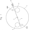
- the core manufacturing apparatus includes: a table 1 that is rotatably disposed; a pair of winding shafts 5, 5 disposed with a rotation center of the table 1 interposed therebetween; a sheet inserting member 10 that inserts a resin sheet S between the winding shafts 5, 5; and chuks 15 (15A, 15B), as a fixing means and a melt-bonding means, which press and fix, and thermally melt-bond the inserted sheet S to the winding shafts 5, 5.
- the table 1 has a disc shape, and a rotating shaft 2 is fixedly mounted at the center of the table 1.
- a pair of winding shafts 5, 5 are disposed at positions on both ends of a diameter passing through the rotating shaft 2 (at axisymmetric positions).
- the table 1 is configured to turn counterclockwise.
- the winding shafts 5, 5 are disposed close to the circumference of the table 1, and positioned horizontally in Fig. 1 as viewed from the front.
- the winding shafts 5, 5 are configured to orbitally move about the rotation center of the table at least one turn by the rotation of the table 1. As the winding shafts 5, 5 orbitally move, they wind up the sheet S inserted from the sheet inserting member 10 while applying tension to the sheet S.
- the sheet inserting member 10 is disposed obliquely above the right side winding shaft 5 in Fig. 1 as viewed from the front.
- the sheet S is inserted from the downstream side of the rotational direction of the right side winding shaft 5 toward the downstream side of the rotational direction of the left side winding shaft 5.
- the chucks 15A, 15B are each disposed on the downstream side of the corresponding respective winding shafts 5, 5. As described above, the chucks 15A, 15B are provided to be able to advance toward and retract from the winding shafts 5, 5, and each have a means for thermally melt-bonding the sheet S.
- the sheet S may have a thickness of about 40-300 ⁇ m, for example, and may be made from any of polyethylene (PE), polypropylene (PP), polyphenylene sulfide (PPS), and polyethylene terephthalate (PET), for example.
- PE polyethylene
- PP polypropylene
- PPS polyphenylene sulfide
- PET polyethylene terephthalate
- the sheet S is inserted between the two winding shafts 5, 5 by the sheet inserting member 10.
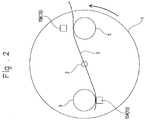
- the first chuck 15A is advanced and moved to press and fix an end of the sheet S, so that the sheet S is brought into contact with the two winding shafts 5, 5. That is, while the front side of the sheet S is pressed and fixed to the downstream side surface of the first winding shaft 5, the back side of the sheet S is brought into contact with the downstream side surface of the second winding shaft 5.
- the sheet S is arranged diagonally between the two winding shafts 5, 5.
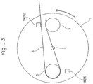
- the table 1 is rotated a half turn counterclockwise, so as to allow the sheet S to be wound around and along the circumferential surface of the second winding shaft 5 as shown in Fig. 3 .
- the first chuck 15A is configured to be movable (retractable), for example, in the rotational axis direction, so that the chuck 15A is not caught in the sheet S during the half turn motion.
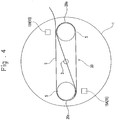
- the table 1 is rotated another half turn counterclockwise, so as to allow the sheet S to be wound around and along the circumferential surface of the first winding shaft 5 as shown in Fig. 4 .
- the second chuck 15B is configured to be movable (retractable), for example, in the rotational axis direction, so that the chuck 15B is not caught in the sheet S during the half turn motion.
- the table 1 When the sheet S has been wound around the two winding shafts 5, 5, the table 1 is stopped from rotating. Then, the chucks 15A, 15B are moved forward in the direction of the arrow (the direction toward the winding shafts 5, 5) to adhesively bond (or thermally melt-bond) respective curved portions of the sheet S, and the wound sheet S is cut at a portion close to a free end to thereby provide the core 20.
- the table 1 is rotated one turn, but alternatively it may be rotated two or three turns.
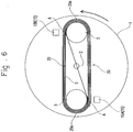
- the core 20 is configured in such a manner that the inner side of a first end of the sheet S is joined to the outer side of a predetermined location of the sheet S, and the inner side of the second end of the sheet S is joined to the inner side of a different predetermined location of the sheet S.
- the core 20 has a shape that looks like the numeral "6" being flattened by pressure applied in the direction crossing the surface of the sheet S.
- the core 20 has curved portions 20a, 20a that project in different directions from each other and are of substantially the same size as each other, as well as having the portion of the sheet S extending diagonally across inside the annularly shaped portion of the sheet S. Because of this structure, the strength of the core is enhanced.
- a pair of sheet-shaped separators 23, 23 are fed out by an unshown feeder, and overlapped at one ends thereof and joined to the joining location A of the core 20.
- the tension of the wound sheet S is maintained.
- tensile force constantly acts in the outward direction so as to maintain the oblong shape, thereby further enhancing the strength of the core 20.
- the separators 23 each may have a thickness of about 20-30 ⁇ m, for example, and may be made from either polyethylene or polypropylene, for example.
- the thus manufactured cell 30 is provided with the core 20 that has curved portions 20a, 20a projecting in different directions from each other, which imparts to the cell 30 high strength against inward pressure applied in the long axis direction of the core 20.
- the cell 30 is provided with the portion of the sheet S that extends diagonally between the joining locations A, A across inside the annularly shaped portion of the sheet S, which imparts to the cell 30 high strength against inward pressure applied in the short axis direction of the core 20. That is, the cell 30 is manufactured ensuring high strength regardless of pressure applied in either direction.
- Fig. 8 Rectangular samples as shown in Fig. 8(a) are prepared for the sheet S and the separator 23, and strength tests are carried out using a testing apparatus shown in Fig. 8(b) .
- a pair of supports 60, 60 having a triangular cross section are arranged with a predetermined distance L therebetween, and each sample is placed horizontally on the tops of the supports 60, 60.
- the amount of deflection T is determined by finding out the extents to which the sheet S and the separator 23 are bent, and a sample that has a smaller amount of deflection T is referred to as having higher strength.
- the present invention requires the sheet S have higher strength (have a smaller amount of deflection) than the separator 23.
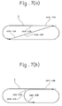
- the core is configured in such a manner that the inner side of the first end of the sheet S is joined to the outer side of the predetermined location of the sheet S, and the inner side of the second end of the sheet S is joined to the inner side of the different predetermined location of the sheet S (cf., Fig. 7(a) ).
- the core may be configured in such a manner that the inner side of the first end of the sheet S is joined to the outer side of the predetermined location of the sheet S, and the outer side of the second end of the sheet S is joined to the inner side of the different predetermined location of the sheet S.
- the sheet S is wound up in such a manner that the sheet S is inserted between the two winding shafts 5, 5 and then pressed and fixed at its end to the first winding shaft 5, and in this state, the table 1 is rotated while the second winding shaft 5 is pressed onto the back side of the sheet S.
- the table 1 is rotated while the second winding shaft 5 is pressed onto the back side of the sheet S.
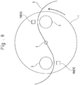
- the sheet S may be wound up in such a manner that the sheet S is inserted between the two winding shafts 5, 5 and pressed, with the first winding shaft 5 pressing the front side of the sheet S and the second winding shaft 5 pressing the back side of the sheet S, and in this state, the table 1 is rotated at least a half turn, for example, to form the sheet S into a shape that looks like the letter "S" or numeral "8" being flattened by pressure applied in the vertical direction (cf., Fig. 11 ).
- the sheet S is wound in one direction at the two winding shafts 5, 5 to form a core 200 having at both sides curved portions 200a, 200a that are of substantially the same shape.
- the thus formed core 200 has the two curved portions 200a, 200a projecting in different directions from each other, as well as having a linear portion, extending between the two curved portions 200a, 200a, which links with the opposite side ends of the respective curved portions 200a, 200a. Accordingly, as with the above-described embodiment, it is possible to increase strength against external pressure and to prevent or reduce the deflection of electrode plates.
- the winding shafts 5, 5 may be controlled to be driven independently of each other so that the first winding shaft 5 presses the front side of the sheet S and the second winding shaft 5 presses the back side of the sheet S.
- the pair of winding shafts 5, 5 are provided which are disposed with the rotation center of the table 1 interposed therebetween.
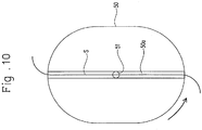
- a single oblong winding shaft 50 may be rotatably provided, in which a groove 50a is formed along the long axis direction of the winding shaft 50, so that the sheet S is inserted in the groove 50a and the table 1 is rotated in such a state.
- This embodiment also provides the core 200a as shown in Fig. 11 .
- the numeral 51 in Fig. 10 denotes a rotating shaft.
- thermal melt bonding is employed to join portions of the sheet S, but alternatively joining by the use of either a hot melt bonding or a tape adhesive may be employed.
- the description of the above embodiment is directed to cores used in cells, but the above embodiment may provide cores for use in other applications as well as in cells.
Landscapes
- Engineering & Computer Science (AREA)
- Manufacturing & Machinery (AREA)
- Chemical & Material Sciences (AREA)
- Chemical Kinetics & Catalysis (AREA)
- Electrochemistry (AREA)
- General Chemical & Material Sciences (AREA)
- Secondary Cells (AREA)
- Storage Of Web-Like Or Filamentary Materials (AREA)
- Primary Cells (AREA)
Claims (12)
- Verfahren zum Herstellen einer Zelle, umfassend:einen ersten Schritt des Herstellens eines Kerns (20) unter Verwendung einer Kernherstellungseinrichtung, wobei die Einrichtung ein Paar Wickelwellen (5, 5) aufweist, die mit einem Drehzentrum der Einrichtung dazwischen zwischengeordnet angeordnet sind, wobei sich das Paar Wickelwellen (5, 5) um das Drehzentrum dreht, undeinen zweiten Schritt des Fertigens eines geschichteten Elektrodenelements (25) mit einer blattförmigen positiven Elektrode (21), einer blattförmigen negativen Elektrode (22) und blattförmigen Abscheidern (23, 23) und des Wickelns des geschichteten Elektrodenelements (25) um eine Umfangsfläche des Kerns (20), wobei der erste Schritt Folgendes umfasst:Einsetzen eines Blatts (S) zwischen den Wickelwellen (5, 5),Drehen des Paars Wickelwellen (5, 5) um einen vorbestimmten Winkel undVerbinden von überlappten Abschnitten des Blatts (S) durch mindestens eine einer Klebebindung und Schmelzbindung.
- Verfahren zum Herstellen einer Zelle nach Anspruch 1, wobei die Abscheider (23, 23) an einem Ende davon überlappt und durch mindestens eine einer Klebebindung und Schmelzbindung mit dem Blatt (S) verbunden sind.
- Verfahren zum Herstellen einer Zelle nach einem der Ansprüche 1 und 2, wobei das Blatt (S) eine höhere Festigkeit als der Abscheider (23) hat.
- Kernherstellungseinrichtung, umfassend:ein Paar Wickelwellen (5, 5), die mit einem Drehzentrum der Einrichtung dazwischen zwischengeordnet angeordnet sind, wobei sich das Paar Wickelwellen (5, 5) um das Drehzentrum dreht,ein Blatteinsetzungselement (10), das angeordnet ist, um ein Blatt (S) zwischen den Wickelwellen (5, 5) einzusetzen, undVerbindungselemente (15, 15), die angeordnet sind, um überlappte Abschnitte des Blatts (S) miteinander durch Klebebindung oder Schmelzbindung in einem Zustand zu verbinden, in dem das Paar Wickelwellen (5, 5) um einen vorbestimmten Winkel gedreht wurde.
- Kernherstellungseinrichtung, umfassend:eine einzelne längliche Wickelwelle (50), die eine Nut (50a) aufweist, die entlang der langen Achsenrichtung der Wickelwelle (50) gebildet ist, und um eine Drehwelle (51) rotierbar ist,ein Blatteinsetzungselement (10), das angeordnet ist, um ein Blatt (S) in die Nut (50a) einzusetzen, undVerbindungselemente (15; 15), die angeordnet sind, um überlappte Abschnitte des Blatts (S) miteinander durch Klebebindung oder Schmelzbindung in einem Zustand zu verbinden, in dem die einzelne längliche Wickelwelle (50) um einen vorbestimmten Winkel gedreht wurde.
- Kernherstellungseinrichtung nach Anspruch 4 oder 5, wobei die Verbindungselemente (15, 15) angeordnet sind, um die überlappten Abschnitte durch mindestens eine einer Klebebindung und Schmelzbindung zu verbinden, und die Verbindungselemente (15, 15) angeordnet sind, um hin zu der ersten und der zweiten Wickelwelle (5, 5) vorzurücken und sich davon zurückzuziehen.
- Kern, umfassend ein Blatt (S), wobei das Blatt (s) ein erstes Ende, das mit einer ersten Stelle des Blatts (S) verbunden ist, und ein zweites Ende, das mit einer zweiten Stelle des Blatts (S) verbunden ist, hat, wobei das Blatt (S) einen Abschnitt hat, der sich zwischen den ersten Stellen und der zweiten Stelle im Inneren des Kerns zwischen ringförmig geformten Abschnitten des Blatts (S) erstreckt.
- Kern nach Anspruch 7, wobei eine Innenseite des ersten Endes des Blatts (S) mit einer Außenseite der ersten Stelle des Blatts (S) verbunden ist und eine Innenseite des zweiten Endes des Blatts (S) mit einer Innenseite der zweiten Stelle des Blatts (S) verbunden ist.
- Kern nach Anspruch 7, wobei eine Innenseite des ersten Endes des Blatts (S) mit einer Außenseite der ersten Stelle des Blatts (S) verbunden ist und eine Außenseite des zweiten Endes des Blatts (S) mit einer Innenseite der zweiten Stelle des Blatts (S) verbunden ist.
- Kern nach Anspruch 7, wobei der Kern zwei ringförmig geformte Abschnitte (100a, 200a) und einen linearen Abschnitt hat, der sich diagonal zwischen den zwei ringförmig geformten Abschnitten (200a, 200a) erstreckt.
- Kern nach Anspruch 7, wobei der Kern in einer S-Form gewunden ist.
- Zelle, umfassend den Kern nach einem der Ansprüche 7-11.
Applications Claiming Priority (2)
| Application Number | Priority Date | Filing Date | Title |
|---|---|---|---|
| JP2009017894 | 2009-01-29 | ||
| PCT/JP2010/051089 WO2010087384A1 (ja) | 2009-01-29 | 2010-01-28 | 電池及び電池の製造方法と、電池における巻芯の製造方法及び巻芯製造装置並びに巻芯 |
Publications (3)
| Publication Number | Publication Date |
|---|---|
| EP2393149A1 EP2393149A1 (de) | 2011-12-07 |
| EP2393149A4 EP2393149A4 (de) | 2017-01-18 |
| EP2393149B1 true EP2393149B1 (de) | 2018-03-14 |
Family
ID=42395642
Family Applications (1)
| Application Number | Title | Priority Date | Filing Date |
|---|---|---|---|
| EP10735849.1A Active EP2393149B1 (de) | 2009-01-29 | 2010-01-28 | Batterie und verfahren zur herstellung einer batterie sowie verfahren zur batteriekernherstellung, vorrichtung zur kernherstellung und kern |
Country Status (7)
| Country | Link |
|---|---|
| US (1) | US9112233B2 (de) |
| EP (1) | EP2393149B1 (de) |
| JP (2) | JP5582408B2 (de) |
| KR (1) | KR101708731B1 (de) |
| CN (1) | CN102282714B (de) |
| TW (1) | TWI450436B (de) |
| WO (1) | WO2010087384A1 (de) |
Families Citing this family (14)
| Publication number | Priority date | Publication date | Assignee | Title |
|---|---|---|---|---|
| WO2012137926A1 (ja) * | 2011-04-07 | 2012-10-11 | 日産自動車株式会社 | 電極積層装置および電極積層方法 |
| JP5777244B2 (ja) * | 2011-07-06 | 2015-09-09 | 株式会社Gsユアサ | 巻回型蓄電素子 |
| JP5948987B2 (ja) * | 2012-03-12 | 2016-07-06 | 株式会社Gsユアサ | 蓄電素子、電極体、芯材及び巻軸 |
| WO2013164884A1 (ja) * | 2012-05-01 | 2013-11-07 | 日立ビークルエナジー株式会社 | 扁平捲回形二次電池およびその製造方法 |
| JP2013232439A (ja) * | 2012-05-01 | 2013-11-14 | Hitachi Vehicle Energy Ltd | 扁平捲回形二次電池およびその製造方法 |
| WO2014207883A1 (ja) * | 2013-06-28 | 2014-12-31 | 日立オートモティブシステムズ株式会社 | 扁平捲回形二次電池 |
| JP6274650B2 (ja) * | 2014-01-28 | 2018-02-07 | 株式会社Gsユアサ | 蓄電素子及び蓄電素子の製造方法 |
| JP6591298B2 (ja) * | 2016-01-20 | 2019-10-16 | 株式会社皆藤製作所 | 巻回装置 |
| JP6065139B2 (ja) * | 2016-03-28 | 2017-01-25 | 株式会社Gsユアサ | 蓄電素子、電極体及び芯材 |
| CN107768737A (zh) * | 2017-11-24 | 2018-03-06 | 天津冶金职业技术学院 | 一种3mm电池电极芯绕卷用工装 |
| WO2019235476A1 (ja) * | 2018-06-07 | 2019-12-12 | 株式会社Gsユアサ | 蓄電素子 |
| CN111354968B (zh) * | 2018-12-21 | 2025-05-27 | 江苏时代新能源科技有限公司 | 卷绕装置 |
| JP6807115B2 (ja) * | 2019-09-12 | 2021-01-06 | 株式会社皆藤製作所 | 巻回装置 |
| CN115985682B (zh) * | 2023-03-22 | 2023-06-02 | 深圳江浩电子有限公司 | 一种车载电容器 |
Family Cites Families (17)
| Publication number | Priority date | Publication date | Assignee | Title |
|---|---|---|---|---|
| GB1340314A (en) * | 1972-04-10 | 1973-12-12 | Windings Inc | Package of elongate flexible material and method and apparatus for producing such a package |
| JPS62195860A (ja) | 1986-02-24 | 1987-08-28 | Shin Kobe Electric Mach Co Ltd | 渦巻電極体の製造法 |
| JPH06104519B2 (ja) | 1991-10-24 | 1994-12-21 | 株式会社エイチイーシー | 帯状物の巻取装置およびその巻取方法 |
| JPH06168736A (ja) | 1992-11-30 | 1994-06-14 | Sanyo Electric Co Ltd | 渦巻電極体の製造方法 |
| JP3221324B2 (ja) * | 1996-08-22 | 2001-10-22 | 松下電器産業株式会社 | 薄型電池およびその製造法 |
| JPH10270069A (ja) | 1997-03-27 | 1998-10-09 | Mitsubishi Cable Ind Ltd | 角型電池およびその製造方法 |
| JP2000156241A (ja) | 1998-11-19 | 2000-06-06 | Japan Storage Battery Co Ltd | 電 池 |
| JP2000340263A (ja) * | 1999-05-28 | 2000-12-08 | Japan Storage Battery Co Ltd | 非水電解質二次電池 |
| JP2001126769A (ja) | 1999-10-27 | 2001-05-11 | Shin Kobe Electric Mach Co Ltd | 円筒形リチウムイオン電池 |
| JP2001229974A (ja) * | 2000-02-16 | 2001-08-24 | Shin Kobe Electric Mach Co Ltd | 円筒形リチウムイオン電池 |
| US6485859B1 (en) | 2000-11-21 | 2002-11-26 | Alfred E. Mann Foundation For Scientific Research | Resilient mandrel for battery electrode assembly |
| JP2003242970A (ja) * | 2002-02-12 | 2003-08-29 | Japan Storage Battery Co Ltd | 電 池 |
| JP2003249257A (ja) | 2002-02-25 | 2003-09-05 | Kaido Seisakusho:Kk | 電池素子材料の捲回装置用巻芯 |
| JP2003346880A (ja) | 2002-05-24 | 2003-12-05 | Japan Storage Battery Co Ltd | 電 池 |
| JP2003346879A (ja) * | 2002-05-24 | 2003-12-05 | Japan Storage Battery Co Ltd | 電 池 |
| JP2007207649A (ja) | 2006-02-03 | 2007-08-16 | Matsushita Electric Ind Co Ltd | 角型非水電解液電池の製造法 |
| JP4656451B2 (ja) | 2008-04-03 | 2011-03-23 | トヨタ自動車株式会社 | 捲回電極体の製造方法および電極巻取装置 |
-
2010
- 2010-01-28 CN CN201080004893.7A patent/CN102282714B/zh active Active
- 2010-01-28 JP JP2010548539A patent/JP5582408B2/ja active Active
- 2010-01-28 EP EP10735849.1A patent/EP2393149B1/de active Active
- 2010-01-28 US US13/146,781 patent/US9112233B2/en active Active
- 2010-01-28 KR KR1020117017183A patent/KR101708731B1/ko active Active
- 2010-01-28 TW TW99102420A patent/TWI450436B/zh active
- 2010-01-28 WO PCT/JP2010/051089 patent/WO2010087384A1/ja not_active Ceased
-
2014
- 2014-07-18 JP JP2014147637A patent/JP5867836B2/ja active Active
Non-Patent Citations (1)
| Title |
|---|
| None * |
Also Published As
| Publication number | Publication date |
|---|---|
| CN102282714B (zh) | 2014-03-05 |
| EP2393149A4 (de) | 2017-01-18 |
| JP2014239049A (ja) | 2014-12-18 |
| JP5582408B2 (ja) | 2014-09-03 |
| KR20110131170A (ko) | 2011-12-06 |
| US9112233B2 (en) | 2015-08-18 |
| TWI450436B (zh) | 2014-08-21 |
| TW201036238A (en) | 2010-10-01 |
| JP5867836B2 (ja) | 2016-02-24 |
| CN102282714A (zh) | 2011-12-14 |
| KR101708731B1 (ko) | 2017-02-21 |
| EP2393149A1 (de) | 2011-12-07 |
| JPWO2010087384A1 (ja) | 2012-08-02 |
| WO2010087384A1 (ja) | 2010-08-05 |
| US20110287293A1 (en) | 2011-11-24 |
Similar Documents
| Publication | Publication Date | Title |
|---|---|---|
| EP2393149B1 (de) | Batterie und verfahren zur herstellung einer batterie sowie verfahren zur batteriekernherstellung, vorrichtung zur kernherstellung und kern | |
| US9620755B2 (en) | Secondary battery manufacturing method, secondary battery, welding apparatus thereof | |
| EP3951968B1 (de) | Vorrichtung und verfahren zur herstellung einer elektrodenanordnung | |
| CN103891024B (zh) | 具备螺旋电极体的电池及其制造方法 | |
| KR102769698B1 (ko) | 전극 조립체 제조방법과, 이를 통해 제조된 전극 조립체 및 이차전지 | |
| WO2013105361A1 (ja) | 超音波溶接用チップ、超音波溶接機、及び電池の製造方法 | |
| JP2012517658A (ja) | ボタン電池とそれを製造する方法 | |
| CN101636858A (zh) | 二次电池以及二次电池的制造方法 | |
| JP2009193750A (ja) | 非水系二次電池用極板群の製造方法およびそれを用いた非水系二次電池用極板群と非水系二次電池 | |
| JP2000156241A (ja) | 電 池 | |
| JP2008166030A (ja) | 渦巻電極体の製造方法及びこれを用いた密閉型電池の製造方法 | |
| US20220190309A1 (en) | Method for producing an electrode sheet | |
| CN111341945B (zh) | 电芯及电池 | |
| JP2026053730A (ja) | 電極群および接合方法 | |
| US20190074550A1 (en) | Electrode assembly for secondary battery and method for producing electrode assembly for secondary battery | |
| KR102848069B1 (ko) | 멀티 탭의 용접 강도 측정방법 | |
| CN117039103A (zh) | 电芯压胶装置 | |
| EP4207411A2 (de) | Elektrodenanordnung für sekundärbatterie und verfahren zur herstellung davon | |
| CN114667636A (zh) | 一种柔性电池及其制造方法 | |
| EP4557415A1 (de) | Vorrichtung und verfahren zur neuformung einer elektrodenanordnung | |
| EP4583214A1 (de) | Elektrodenfolienerwärmungsvorrichtung, elektrodenfolienerwärmungsverfahren und jelly-roll-elektrodenanordnung | |
| JP7824967B2 (ja) | 接合方法 | |
| EP4293768A1 (de) | Verfahren zur herstellung einer elektrodenanordnung | |
| EP4057409A2 (de) | Vorrichtung zur herstellung einer batteriezelle | |
| EP4648151A1 (de) | Gekrümmte sekundärbatterie mit elektrodenträger und herstellungsverfahren dafür |
Legal Events
| Date | Code | Title | Description |
|---|---|---|---|
| PUAI | Public reference made under article 153(3) epc to a published international application that has entered the european phase |
Free format text: ORIGINAL CODE: 0009012 |
|
| 17P | Request for examination filed |
Effective date: 20110804 |
|
| AK | Designated contracting states |
Kind code of ref document: A1 Designated state(s): AT BE BG CH CY CZ DE DK EE ES FI FR GB GR HR HU IE IS IT LI LT LU LV MC MK MT NL NO PL PT RO SE SI SK SM TR |
|
| DAX | Request for extension of the european patent (deleted) | ||
| RA4 | Supplementary search report drawn up and despatched (corrected) |
Effective date: 20161215 |
|
| RIC1 | Information provided on ipc code assigned before grant |
Ipc: H01M 6/02 20060101ALI20161209BHEP Ipc: H01M 10/04 20060101AFI20161209BHEP |
|
| GRAP | Despatch of communication of intention to grant a patent |
Free format text: ORIGINAL CODE: EPIDOSNIGR1 |
|
| STAA | Information on the status of an ep patent application or granted ep patent |
Free format text: STATUS: GRANT OF PATENT IS INTENDED |
|
| INTG | Intention to grant announced |
Effective date: 20170925 |
|
| GRAS | Grant fee paid |
Free format text: ORIGINAL CODE: EPIDOSNIGR3 |
|
| GRAA | (expected) grant |
Free format text: ORIGINAL CODE: 0009210 |
|
| STAA | Information on the status of an ep patent application or granted ep patent |
Free format text: STATUS: THE PATENT HAS BEEN GRANTED |
|
| AK | Designated contracting states |
Kind code of ref document: B1 Designated state(s): AT BE BG CH CY CZ DE DK EE ES FI FR GB GR HR HU IE IS IT LI LT LU LV MC MK MT NL NO PL PT RO SE SI SK SM TR |
|
| REG | Reference to a national code |
Ref country code: GB Ref legal event code: FG4D |
|
| REG | Reference to a national code |
Ref country code: CH Ref legal event code: EP Ref country code: AT Ref legal event code: REF Ref document number: 979695 Country of ref document: AT Kind code of ref document: T Effective date: 20180315 |
|
| REG | Reference to a national code |
Ref country code: IE Ref legal event code: FG4D |
|
| REG | Reference to a national code |
Ref country code: DE Ref legal event code: R096 Ref document number: 602010049170 Country of ref document: DE |
|
| REG | Reference to a national code |
Ref country code: NL Ref legal event code: MP Effective date: 20180314 |
|
| REG | Reference to a national code |
Ref country code: LT Ref legal event code: MG4D |
|
| PG25 | Lapsed in a contracting state [announced via postgrant information from national office to epo] |
Ref country code: FI Free format text: LAPSE BECAUSE OF FAILURE TO SUBMIT A TRANSLATION OF THE DESCRIPTION OR TO PAY THE FEE WITHIN THE PRESCRIBED TIME-LIMIT Effective date: 20180314 Ref country code: LT Free format text: LAPSE BECAUSE OF FAILURE TO SUBMIT A TRANSLATION OF THE DESCRIPTION OR TO PAY THE FEE WITHIN THE PRESCRIBED TIME-LIMIT Effective date: 20180314 Ref country code: CY Free format text: LAPSE BECAUSE OF FAILURE TO SUBMIT A TRANSLATION OF THE DESCRIPTION OR TO PAY THE FEE WITHIN THE PRESCRIBED TIME-LIMIT Effective date: 20180314 Ref country code: NO Free format text: LAPSE BECAUSE OF FAILURE TO SUBMIT A TRANSLATION OF THE DESCRIPTION OR TO PAY THE FEE WITHIN THE PRESCRIBED TIME-LIMIT Effective date: 20180614 Ref country code: HR Free format text: LAPSE BECAUSE OF FAILURE TO SUBMIT A TRANSLATION OF THE DESCRIPTION OR TO PAY THE FEE WITHIN THE PRESCRIBED TIME-LIMIT Effective date: 20180314 Ref country code: ES Free format text: LAPSE BECAUSE OF FAILURE TO SUBMIT A TRANSLATION OF THE DESCRIPTION OR TO PAY THE FEE WITHIN THE PRESCRIBED TIME-LIMIT Effective date: 20180314 |
|
| REG | Reference to a national code |
Ref country code: AT Ref legal event code: MK05 Ref document number: 979695 Country of ref document: AT Kind code of ref document: T Effective date: 20180314 |
|
| PG25 | Lapsed in a contracting state [announced via postgrant information from national office to epo] |
Ref country code: BG Free format text: LAPSE BECAUSE OF FAILURE TO SUBMIT A TRANSLATION OF THE DESCRIPTION OR TO PAY THE FEE WITHIN THE PRESCRIBED TIME-LIMIT Effective date: 20180614 Ref country code: LV Free format text: LAPSE BECAUSE OF FAILURE TO SUBMIT A TRANSLATION OF THE DESCRIPTION OR TO PAY THE FEE WITHIN THE PRESCRIBED TIME-LIMIT Effective date: 20180314 Ref country code: SE Free format text: LAPSE BECAUSE OF FAILURE TO SUBMIT A TRANSLATION OF THE DESCRIPTION OR TO PAY THE FEE WITHIN THE PRESCRIBED TIME-LIMIT Effective date: 20180314 Ref country code: GR Free format text: LAPSE BECAUSE OF FAILURE TO SUBMIT A TRANSLATION OF THE DESCRIPTION OR TO PAY THE FEE WITHIN THE PRESCRIBED TIME-LIMIT Effective date: 20180615 |
|
| PG25 | Lapsed in a contracting state [announced via postgrant information from national office to epo] |
Ref country code: EE Free format text: LAPSE BECAUSE OF FAILURE TO SUBMIT A TRANSLATION OF THE DESCRIPTION OR TO PAY THE FEE WITHIN THE PRESCRIBED TIME-LIMIT Effective date: 20180314 Ref country code: NL Free format text: LAPSE BECAUSE OF FAILURE TO SUBMIT A TRANSLATION OF THE DESCRIPTION OR TO PAY THE FEE WITHIN THE PRESCRIBED TIME-LIMIT Effective date: 20180314 Ref country code: RO Free format text: LAPSE BECAUSE OF FAILURE TO SUBMIT A TRANSLATION OF THE DESCRIPTION OR TO PAY THE FEE WITHIN THE PRESCRIBED TIME-LIMIT Effective date: 20180314 Ref country code: PL Free format text: LAPSE BECAUSE OF FAILURE TO SUBMIT A TRANSLATION OF THE DESCRIPTION OR TO PAY THE FEE WITHIN THE PRESCRIBED TIME-LIMIT Effective date: 20180314 |
|
| PG25 | Lapsed in a contracting state [announced via postgrant information from national office to epo] |
Ref country code: AT Free format text: LAPSE BECAUSE OF FAILURE TO SUBMIT A TRANSLATION OF THE DESCRIPTION OR TO PAY THE FEE WITHIN THE PRESCRIBED TIME-LIMIT Effective date: 20180314 Ref country code: SK Free format text: LAPSE BECAUSE OF FAILURE TO SUBMIT A TRANSLATION OF THE DESCRIPTION OR TO PAY THE FEE WITHIN THE PRESCRIBED TIME-LIMIT Effective date: 20180314 Ref country code: SM Free format text: LAPSE BECAUSE OF FAILURE TO SUBMIT A TRANSLATION OF THE DESCRIPTION OR TO PAY THE FEE WITHIN THE PRESCRIBED TIME-LIMIT Effective date: 20180314 Ref country code: CZ Free format text: LAPSE BECAUSE OF FAILURE TO SUBMIT A TRANSLATION OF THE DESCRIPTION OR TO PAY THE FEE WITHIN THE PRESCRIBED TIME-LIMIT Effective date: 20180314 |
|
| REG | Reference to a national code |
Ref country code: DE Ref legal event code: R097 Ref document number: 602010049170 Country of ref document: DE |
|
| PG25 | Lapsed in a contracting state [announced via postgrant information from national office to epo] |
Ref country code: PT Free format text: LAPSE BECAUSE OF FAILURE TO SUBMIT A TRANSLATION OF THE DESCRIPTION OR TO PAY THE FEE WITHIN THE PRESCRIBED TIME-LIMIT Effective date: 20180716 |
|
| PLBE | No opposition filed within time limit |
Free format text: ORIGINAL CODE: 0009261 |
|
| STAA | Information on the status of an ep patent application or granted ep patent |
Free format text: STATUS: NO OPPOSITION FILED WITHIN TIME LIMIT |
|
| PG25 | Lapsed in a contracting state [announced via postgrant information from national office to epo] |
Ref country code: DK Free format text: LAPSE BECAUSE OF FAILURE TO SUBMIT A TRANSLATION OF THE DESCRIPTION OR TO PAY THE FEE WITHIN THE PRESCRIBED TIME-LIMIT Effective date: 20180314 |
|
| 26N | No opposition filed |
Effective date: 20181217 |
|
| PG25 | Lapsed in a contracting state [announced via postgrant information from national office to epo] |
Ref country code: SI Free format text: LAPSE BECAUSE OF FAILURE TO SUBMIT A TRANSLATION OF THE DESCRIPTION OR TO PAY THE FEE WITHIN THE PRESCRIBED TIME-LIMIT Effective date: 20180314 Ref country code: IT Free format text: LAPSE BECAUSE OF FAILURE TO SUBMIT A TRANSLATION OF THE DESCRIPTION OR TO PAY THE FEE WITHIN THE PRESCRIBED TIME-LIMIT Effective date: 20180314 |
|
| PG25 | Lapsed in a contracting state [announced via postgrant information from national office to epo] |
Ref country code: MC Free format text: LAPSE BECAUSE OF FAILURE TO SUBMIT A TRANSLATION OF THE DESCRIPTION OR TO PAY THE FEE WITHIN THE PRESCRIBED TIME-LIMIT Effective date: 20180314 |
|
| REG | Reference to a national code |
Ref country code: CH Ref legal event code: PL |
|
| GBPC | Gb: european patent ceased through non-payment of renewal fee |
Effective date: 20190128 |
|
| PG25 | Lapsed in a contracting state [announced via postgrant information from national office to epo] |
Ref country code: LU Free format text: LAPSE BECAUSE OF NON-PAYMENT OF DUE FEES Effective date: 20190128 |
|
| REG | Reference to a national code |
Ref country code: BE Ref legal event code: MM Effective date: 20190131 |
|
| REG | Reference to a national code |
Ref country code: IE Ref legal event code: MM4A |
|
| PG25 | Lapsed in a contracting state [announced via postgrant information from national office to epo] |
Ref country code: FR Free format text: LAPSE BECAUSE OF NON-PAYMENT OF DUE FEES Effective date: 20190131 |
|
| PG25 | Lapsed in a contracting state [announced via postgrant information from national office to epo] |
Ref country code: BE Free format text: LAPSE BECAUSE OF NON-PAYMENT OF DUE FEES Effective date: 20190131 |
|
| PG25 | Lapsed in a contracting state [announced via postgrant information from national office to epo] |
Ref country code: CH Free format text: LAPSE BECAUSE OF NON-PAYMENT OF DUE FEES Effective date: 20190131 Ref country code: LI Free format text: LAPSE BECAUSE OF NON-PAYMENT OF DUE FEES Effective date: 20190131 Ref country code: GB Free format text: LAPSE BECAUSE OF NON-PAYMENT OF DUE FEES Effective date: 20190128 |
|
| PG25 | Lapsed in a contracting state [announced via postgrant information from national office to epo] |
Ref country code: IE Free format text: LAPSE BECAUSE OF NON-PAYMENT OF DUE FEES Effective date: 20190128 |
|
| PG25 | Lapsed in a contracting state [announced via postgrant information from national office to epo] |
Ref country code: TR Free format text: LAPSE BECAUSE OF FAILURE TO SUBMIT A TRANSLATION OF THE DESCRIPTION OR TO PAY THE FEE WITHIN THE PRESCRIBED TIME-LIMIT Effective date: 20180314 |
|
| PG25 | Lapsed in a contracting state [announced via postgrant information from national office to epo] |
Ref country code: MT Free format text: LAPSE BECAUSE OF NON-PAYMENT OF DUE FEES Effective date: 20190128 |
|
| PG25 | Lapsed in a contracting state [announced via postgrant information from national office to epo] |
Ref country code: IS Free format text: LAPSE BECAUSE OF FAILURE TO SUBMIT A TRANSLATION OF THE DESCRIPTION OR TO PAY THE FEE WITHIN THE PRESCRIBED TIME-LIMIT Effective date: 20180714 |
|
| PG25 | Lapsed in a contracting state [announced via postgrant information from national office to epo] |
Ref country code: HU Free format text: LAPSE BECAUSE OF FAILURE TO SUBMIT A TRANSLATION OF THE DESCRIPTION OR TO PAY THE FEE WITHIN THE PRESCRIBED TIME-LIMIT; INVALID AB INITIO Effective date: 20100128 |
|
| PG25 | Lapsed in a contracting state [announced via postgrant information from national office to epo] |
Ref country code: MK Free format text: LAPSE BECAUSE OF FAILURE TO SUBMIT A TRANSLATION OF THE DESCRIPTION OR TO PAY THE FEE WITHIN THE PRESCRIBED TIME-LIMIT Effective date: 20180314 |
|
| P01 | Opt-out of the competence of the unified patent court (upc) registered |
Effective date: 20230522 |
|
| PGFP | Annual fee paid to national office [announced via postgrant information from national office to epo] |
Ref country code: DE Payment date: 20251217 Year of fee payment: 17 |