EP2393157A1 - Aussenantenne für das Fernsehen - Google Patents
Aussenantenne für das Fernsehen Download PDFInfo
- Publication number
- EP2393157A1 EP2393157A1 EP10382161A EP10382161A EP2393157A1 EP 2393157 A1 EP2393157 A1 EP 2393157A1 EP 10382161 A EP10382161 A EP 10382161A EP 10382161 A EP10382161 A EP 10382161A EP 2393157 A1 EP2393157 A1 EP 2393157A1
- Authority
- EP
- European Patent Office
- Prior art keywords
- securing element
- grid
- boom
- stem
- shaped body
- Prior art date
- Legal status (The legal status is an assumption and is not a legal conclusion. Google has not performed a legal analysis and makes no representation as to the accuracy of the status listed.)
- Withdrawn
Links
- 238000004806 packaging method and process Methods 0.000 description 6
- 239000011810 insulating material Substances 0.000 description 2
- 230000006978 adaptation Effects 0.000 description 1
- 239000007795 chemical reaction product Substances 0.000 description 1
- 230000008878 coupling Effects 0.000 description 1
- 238000010168 coupling process Methods 0.000 description 1
- 238000005859 coupling reaction Methods 0.000 description 1
- 238000009434 installation Methods 0.000 description 1
- 238000000034 method Methods 0.000 description 1
Images


Classifications
-
- H—ELECTRICITY
- H01—ELECTRIC ELEMENTS
- H01Q—ANTENNAS, i.e. RADIO AERIALS
- H01Q1/00—Details of, or arrangements associated with, antennas
- H01Q1/08—Means for collapsing antennas or parts thereof
- H01Q1/084—Pivotable antennas
-
- H—ELECTRICITY
- H01—ELECTRIC ELEMENTS
- H01Q—ANTENNAS, i.e. RADIO AERIALS
- H01Q1/00—Details of, or arrangements associated with, antennas
- H01Q1/08—Means for collapsing antennas or parts thereof
-
- H—ELECTRICITY
- H01—ELECTRIC ELEMENTS
- H01Q—ANTENNAS, i.e. RADIO AERIALS
- H01Q19/00—Combinations of primary active antenna elements and units with secondary devices, e.g. with quasi-optical devices, for giving the antenna a desired directional characteristic
- H01Q19/02—Details
- H01Q19/04—Means for collapsing H-antennas or Yagi antennas
Definitions
- An external antenna for television of the type that comprises at least one grid and one boom with their respective directive elements that are separated by a predetermined distance and characterised in that it comprises at least one grid-securing element, to the boom, which comprises: a stem-shaped body that clamps the boom and a grid prolongation, with an interior passage in the respective direction of each grid, attached to the stem-shaped body so that, in the storage position, the at least one prolongation and the directives elements are in the same horizontal plane and, in the rotation position, the securing element rotates with respect to the boom, causing the prolongation rotate until it reaches the predetermined position.
- Spanish Utility Model No 131427 "ANTENA PARA TELEVISI ⁇ N DE BRAZOS ABATIBLES”, is known in the name of Mr Jose PUCHOL PÉREZ, from 1967, which refers to an antenna for television with folding arms, characterised in that it comprises a hollow prismatic section against which, on the one hand, it receives the mast securing clamp and, longitudinally opposite, the elements arm and the connection to the receiver, which arm is telescopically plugged in and secured by threaded pins, of which one is in the centre of the prismatic section or support and also used to fix a flange, in which the sheets form a cross, the entrance elbows of which are fitted with support projections in its enforcement that vertically determine some coupling mortised and fixing of the arched arms that support the screen, for which reason longitudinal slots are determined at the adequate end for passing winged screws through that optionally apply pressure.
- This invention is an improvement on external antennas for television, because it allows for improved packaging and storage of the same.
- said solution involves the drawback that requires that the packaging takes into account the volume produced by the boom directors and that of the folded arms, so that, even when folded, the volume is still significant.
- the inventors have developed a new antenna that allows only the volume of the actual boom and director elements to be employed, without requiring any more so that only the volume actually used by the structural needs of the antenna are necessary.
- a securing element has been configured which, in a passive position, said element is orientated parallel to and in the same direction as the directors and, in the active position are arranged perpendicular to same as in the background to the invention, so that in the passive position no additional volume is occupied, only that required for the dimensions of the boom and directors, which than recover their ideal operational position when moved to the active position.
- One objective of this invention is an external antenna for television, of the type that comprises at least one grid and one boom with their respective directive elements that are separated by a predetermined distance and characterised in that it comprises at least one grid-securing element, to the boom, which comprises: a stem-shaped body that clamps the boom and a grid prolongation, with an interior passage in the respective direction of each grid, attached to the body in form of a stem so that, in the storage position, the at least one prolongation and the director elements are in the same horizontal plane and, in the rotation position, the securing element rotates with respect to the boom, causing the prolongation rotate until it reaches the predetermined position.
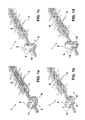
- Figures 1a to 1d illustrate an antenna 1, a boom 4, with its director elements 5, a securing element 6 with its prolongations 8, 9 and a flange 12.
- Figures 2a to 2d show boom 4, then securing element 6 and its prolongations 8, 9 and passages 17, 18, a stem-shaped body 7 with flanges, a first 12 and a second 13, and notches 10, 11, and a slot 15.
- Figure 3 se shows packaging 16, boom 4 and securing element 6 and its prolongations 8, 9.
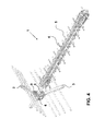
- Figure 4 shows the antenna 1, securing element 6 with its prolongations 8, 9, grids 2, 3, boom 4 and its director elements 5.
- the director elements 5 adopt a horizontal or vertical configuration with respect to boom 4.
- Securing element 6 is arranged in the same plane as director elements 5 so that it occupies just the space that is strictly necessary for the volume needs of the directors 5.
- the antenna is assembled in the following manner. First, the procedure is described from the outside ( Figs. 1a-1d ) in order to subsequently provide details on how to work on the inside of the securing element 6 ( Figs. 2a-2d ).
- the installed then rotates securing element 6 through 90° (or whatever angle is predetermined) and leaves prolongations 8, 9 of the securing element 6 perpendicular to the director element 5 plane ( Fig. 1c ).
- the installation is completed by positioning grids 2, 3 on prolongations 8, 9, leaving the antenna 1 as shown in Figure 4 .
- slot 15 of rotating element 6 fits onto the second flange 13 (ring-shaped) of the stem-shaped body 7.
- Securing element 6 is rotated ( Fig. 2c ) until the passages 17, 18 are facing notches 10, 11.
- Said passages 17, 18 are housings for grids 2, 3 and said notches 10, 11 are used as an end-stop for the referred grids 2, 3.
Landscapes
- Aerials With Secondary Devices (AREA)
Priority Applications (1)
| Application Number | Priority Date | Filing Date | Title |
|---|---|---|---|
| EP10382161A EP2393157A1 (de) | 2010-06-03 | 2010-06-03 | Aussenantenne für das Fernsehen |
Applications Claiming Priority (1)
| Application Number | Priority Date | Filing Date | Title |
|---|---|---|---|
| EP10382161A EP2393157A1 (de) | 2010-06-03 | 2010-06-03 | Aussenantenne für das Fernsehen |
Publications (1)
| Publication Number | Publication Date |
|---|---|
| EP2393157A1 true EP2393157A1 (de) | 2011-12-07 |
Family
ID=42562344
Family Applications (1)
| Application Number | Title | Priority Date | Filing Date |
|---|---|---|---|
| EP10382161A Withdrawn EP2393157A1 (de) | 2010-06-03 | 2010-06-03 | Aussenantenne für das Fernsehen |
Country Status (1)
| Country | Link |
|---|---|
| EP (1) | EP2393157A1 (de) |
Cited By (2)
| Publication number | Priority date | Publication date | Assignee | Title |
|---|---|---|---|---|
| ITUA20161774A1 (it) * | 2016-03-17 | 2017-09-17 | Emme Esse S P A | Staffa di supporto di riflettori di antenne |
| CN110444902A (zh) * | 2019-08-08 | 2019-11-12 | 普联技术有限公司 | 一种智能天线装置和系统 |
Citations (6)
| Publication number | Priority date | Publication date | Assignee | Title |
|---|---|---|---|---|
| ES131427Y (es) | 1967-07-20 | 1968-07-16 | Puchol Perez | Antena para television de brazos abatibles. |
| ES150975Y (es) | 1969-08-04 | 1970-09-16 | Robert Bosch Elektronik Und Photokino, G. M. B. H. | Antena de television para la banda uhf. |
| US3531805A (en) * | 1968-06-28 | 1970-09-29 | Winegard Co | High gain all channel television antenna |
| US4265690A (en) * | 1973-09-24 | 1981-05-05 | Herman Lowenhar | Method of forming transmission lines using tubular extendible structures |
| US20070262912A1 (en) * | 2006-03-31 | 2007-11-15 | Eckwielen Bradley L | Modular digital UHF/VHF antenna |
| EP2194605A1 (de) * | 2008-12-05 | 2010-06-09 | Angel Iglesias S.A. | Antenne |
-
2010
- 2010-06-03 EP EP10382161A patent/EP2393157A1/de not_active Withdrawn
Patent Citations (6)
| Publication number | Priority date | Publication date | Assignee | Title |
|---|---|---|---|---|
| ES131427Y (es) | 1967-07-20 | 1968-07-16 | Puchol Perez | Antena para television de brazos abatibles. |
| US3531805A (en) * | 1968-06-28 | 1970-09-29 | Winegard Co | High gain all channel television antenna |
| ES150975Y (es) | 1969-08-04 | 1970-09-16 | Robert Bosch Elektronik Und Photokino, G. M. B. H. | Antena de television para la banda uhf. |
| US4265690A (en) * | 1973-09-24 | 1981-05-05 | Herman Lowenhar | Method of forming transmission lines using tubular extendible structures |
| US20070262912A1 (en) * | 2006-03-31 | 2007-11-15 | Eckwielen Bradley L | Modular digital UHF/VHF antenna |
| EP2194605A1 (de) * | 2008-12-05 | 2010-06-09 | Angel Iglesias S.A. | Antenne |
Cited By (2)
| Publication number | Priority date | Publication date | Assignee | Title |
|---|---|---|---|---|
| ITUA20161774A1 (it) * | 2016-03-17 | 2017-09-17 | Emme Esse S P A | Staffa di supporto di riflettori di antenne |
| CN110444902A (zh) * | 2019-08-08 | 2019-11-12 | 普联技术有限公司 | 一种智能天线装置和系统 |
Similar Documents
| Publication | Publication Date | Title |
|---|---|---|
| CN107394339B (zh) | 一种基站天线 | |
| DE69802076T2 (de) | Antennensystem, insbesondere zur ausrichtung auf satelliten in niedriger umlaufbahn | |
| EP3316397B1 (de) | Starre mehrstrahlige stereoskopische wendelgruppenantenne und flexible trägervorrichtung für wendelantenne dafür | |
| US20120228436A1 (en) | Spacecraft payload positioning with respect to a virtual pivot point | |
| EP3389138A1 (de) | Niederfrequenter oszillator und multifrequenz-multiport-antennenvorrichtung | |
| US8487830B2 (en) | Antenna with long focal length that is compact, robust and can be tested on the ground, mounted on a satellite | |
| CN102612787A (zh) | 一种天线杆系统和支撑装置 | |
| US8770536B2 (en) | Clipping apparatus for expansion card | |
| CN109004331B (zh) | 高刚度可收展抛物柱面天线 | |
| EP1705745A1 (de) | Antennenbefestigung mit Stellexzenter zur Feinjustage | |
| CN112018487B (zh) | 一种可展开螺旋天线、通信系统、雷达、电子对抗系统 | |
| US10608316B2 (en) | Ka-band antenna with fine azimuth and elevation adjustment | |
| US9466889B2 (en) | Tracking antenna system adaptable for use in discrete radio frequency spectrums | |
| EP3229313B1 (de) | Dreiachsiger reflektoreinsatz und positioniermechanismus | |
| KR101797164B1 (ko) | 안테나 시스템 | |
| CA2860405C (en) | Rotatable gps compass and method | |
| US20120211632A1 (en) | Supporting pedestal and related antenna system | |
| CN205863380U (zh) | 一种双极化辐射振子及一种多频多端口天线装置 | |
| US7642961B1 (en) | Remote control antenna positioning system | |
| CN204144452U (zh) | 一种可收折式大孔径测向天线阵 | |
| EP3467936B1 (de) | Drahtanordnung mit uhrfederdurchgängen | |
| CN207587956U (zh) | 一种馈源阵列安装架 | |
| KR101857803B1 (ko) | 항공우주용 광학장치 | |
| CN205355254U (zh) | 提高异极化隔离的双极化基站天线 | |
| Tingay et al. | Parsec-Scale Morphology of PKS 2152-699 and the Radio/Optical Misalignment |
Legal Events
| Date | Code | Title | Description |
|---|---|---|---|
| AK | Designated contracting states |
Kind code of ref document: A1 Designated state(s): AL AT BE BG CH CY CZ DE DK EE ES FI FR GB GR HR HU IE IS IT LI LT LU LV MC MK MT NL NO PL PT RO SE SI SK SM TR |
|
| AX | Request for extension of the european patent |
Extension state: BA ME RS |
|
| PUAI | Public reference made under article 153(3) epc to a published international application that has entered the european phase |
Free format text: ORIGINAL CODE: 0009012 |
|
| STAA | Information on the status of an ep patent application or granted ep patent |
Free format text: STATUS: THE APPLICATION IS DEEMED TO BE WITHDRAWN |
|
| 18D | Application deemed to be withdrawn |
Effective date: 20120609 |