EP2393230A2 - Station de base - Google Patents
Station de base Download PDFInfo
- Publication number
- EP2393230A2 EP2393230A2 EP11168534A EP11168534A EP2393230A2 EP 2393230 A2 EP2393230 A2 EP 2393230A2 EP 11168534 A EP11168534 A EP 11168534A EP 11168534 A EP11168534 A EP 11168534A EP 2393230 A2 EP2393230 A2 EP 2393230A2
- Authority
- EP
- European Patent Office
- Prior art keywords
- base station
- cell
- mobile terminal
- femto
- interference
- Prior art date
- Legal status (The legal status is an assumption and is not a legal conclusion. Google has not performed a legal analysis and makes no representation as to the accuracy of the status listed.)
- Withdrawn
Links
- 238000004891 communication Methods 0.000 claims abstract description 97
- 230000000116 mitigating effect Effects 0.000 claims abstract description 35
- 230000005540 biological transmission Effects 0.000 claims description 161
- 238000001228 spectrum Methods 0.000 claims description 70
- 238000012937 correction Methods 0.000 claims description 10
- 230000001413 cellular effect Effects 0.000 abstract description 4
- 238000000034 method Methods 0.000 description 45
- 230000008569 process Effects 0.000 description 35
- 238000010586 diagram Methods 0.000 description 24
- 238000013468 resource allocation Methods 0.000 description 17
- 238000012545 processing Methods 0.000 description 16
- 230000015556 catabolic process Effects 0.000 description 15
- 238000006731 degradation reaction Methods 0.000 description 15
- 238000005259 measurement Methods 0.000 description 12
- 101000741965 Homo sapiens Inactive tyrosine-protein kinase PRAG1 Proteins 0.000 description 4
- 102100038659 Inactive tyrosine-protein kinase PRAG1 Human genes 0.000 description 4
- 230000009467 reduction Effects 0.000 description 3
- 230000035945 sensitivity Effects 0.000 description 3
- 230000000694 effects Effects 0.000 description 2
- 230000006870 function Effects 0.000 description 2
- 230000006872 improvement Effects 0.000 description 2
- 230000007246 mechanism Effects 0.000 description 2
- 230000008054 signal transmission Effects 0.000 description 2
- 230000003044 adaptive effect Effects 0.000 description 1
- 230000008901 benefit Effects 0.000 description 1
- 238000013461 design Methods 0.000 description 1
- 238000005516 engineering process Methods 0.000 description 1
- 230000010365 information processing Effects 0.000 description 1
- 238000009434 installation Methods 0.000 description 1
- 230000002452 interceptive effect Effects 0.000 description 1
- 238000013507 mapping Methods 0.000 description 1
- 230000004048 modification Effects 0.000 description 1
- 238000012986 modification Methods 0.000 description 1
- 230000004044 response Effects 0.000 description 1
Images









Classifications
-
- H—ELECTRICITY
- H04—ELECTRIC COMMUNICATION TECHNIQUE
- H04L—TRANSMISSION OF DIGITAL INFORMATION, e.g. TELEGRAPHIC COMMUNICATION
- H04L1/00—Arrangements for detecting or preventing errors in the information received
- H04L1/0001—Systems modifying transmission characteristics according to link quality, e.g. power backoff
- H04L1/0002—Systems modifying transmission characteristics according to link quality, e.g. power backoff by adapting the transmission rate
- H04L1/0003—Systems modifying transmission characteristics according to link quality, e.g. power backoff by adapting the transmission rate by switching between different modulation schemes
-
- H—ELECTRICITY
- H04—ELECTRIC COMMUNICATION TECHNIQUE
- H04W—WIRELESS COMMUNICATION NETWORKS
- H04W72/00—Local resource management
- H04W72/50—Allocation or scheduling criteria for wireless resources
- H04W72/54—Allocation or scheduling criteria for wireless resources based on quality criteria
- H04W72/541—Allocation or scheduling criteria for wireless resources based on quality criteria using the level of interference
-
- H—ELECTRICITY
- H04—ELECTRIC COMMUNICATION TECHNIQUE
- H04L—TRANSMISSION OF DIGITAL INFORMATION, e.g. TELEGRAPHIC COMMUNICATION
- H04L1/00—Arrangements for detecting or preventing errors in the information received
- H04L1/0001—Systems modifying transmission characteristics according to link quality, e.g. power backoff
- H04L1/0009—Systems modifying transmission characteristics according to link quality, e.g. power backoff by adapting the channel coding
-
- H—ELECTRICITY
- H04—ELECTRIC COMMUNICATION TECHNIQUE
- H04L—TRANSMISSION OF DIGITAL INFORMATION, e.g. TELEGRAPHIC COMMUNICATION
- H04L1/00—Arrangements for detecting or preventing errors in the information received
- H04L1/0001—Systems modifying transmission characteristics according to link quality, e.g. power backoff
- H04L1/0023—Systems modifying transmission characteristics according to link quality, e.g. power backoff characterised by the signalling
- H04L1/0025—Transmission of mode-switching indication
-
- H—ELECTRICITY
- H04—ELECTRIC COMMUNICATION TECHNIQUE
- H04B—TRANSMISSION
- H04B2201/00—Indexing scheme relating to details of transmission systems not covered by a single group of H04B3/00 - H04B13/00
- H04B2201/69—Orthogonal indexing scheme relating to spread spectrum techniques in general
- H04B2201/707—Orthogonal indexing scheme relating to spread spectrum techniques in general relating to direct sequence modulation
- H04B2201/70702—Intercell-related aspects
-
- H—ELECTRICITY
- H04—ELECTRIC COMMUNICATION TECHNIQUE
- H04W—WIRELESS COMMUNICATION NETWORKS
- H04W16/00—Network planning, e.g. coverage or traffic planning tools; Network deployment, e.g. resource partitioning or cells structures
- H04W16/24—Cell structures
- H04W16/32—Hierarchical cell structures
-
- H—ELECTRICITY
- H04—ELECTRIC COMMUNICATION TECHNIQUE
- H04W—WIRELESS COMMUNICATION NETWORKS
- H04W28/00—Network traffic management; Network resource management
- H04W28/16—Central resource management; Negotiation of resources or communication parameters, e.g. negotiating bandwidth or QoS [Quality of Service]
- H04W28/18—Negotiating wireless communication parameters
-
- H—ELECTRICITY
- H04—ELECTRIC COMMUNICATION TECHNIQUE
- H04W—WIRELESS COMMUNICATION NETWORKS
- H04W84/00—Network topologies
- H04W84/02—Hierarchically pre-organised networks, e.g. paging networks, cellular networks, WLAN [Wireless Local Area Network] or WLL [Wireless Local Loop]
- H04W84/04—Large scale networks; Deep hierarchical networks
- H04W84/042—Public Land Mobile systems, e.g. cellular systems
- H04W84/045—Public Land Mobile systems, e.g. cellular systems using private Base Stations, e.g. femto Base Stations, home Node B
Definitions
- the present invention relates to a radio base station device constituting a radio communication system.
- Orthogonal Frequency-Division Multiple Access is a user multiplexing scheme that is often used in radio communications.
- OFDMA simultaneous access of a plurality of mobile terminals (MTs) is realized by assigning some of a large number of subcarriers, which are prepared by the Orthogonal Frequency Division Multiplexing (OFDM) scheme, to the mobile terminals as frequency resources.
- the OFDMA scheme requires assignment of frequency resources used in data communication before data transmission.
- a base station (BS) determines the frequency resource assignment, and notifies each mobile terminal of the frequency resource assignment information through a dedicated control information channel.
- the base station assigns frequency resources to each mobile terminal according to the amount of data to be transmitted to the particular mobile terminal, and the like.
- Each mobile terminal is notified by the base station of the frequency resource assignment information through the control information channel, at the same time as the data transmission or prior to the data transmission.
- the base station transmits data by using the frequency resources assigned to each mobile terminal.
- the mobile terminal receiving the data from the base station determines which frequency resources are used for the data transmission, according to the frequency resource assignment information from the base station. Then, the particular mobile terminal receives the data based on the frequency resources determined as described above.
- each mobile terminal notifies the base station of a data transmission request and information on the desired data amount to be transmitted.
- the base station assigns frequency resources to each mobile terminal based on the notification, such as the data transmission request, from the particular mobile terminal.
- Each mobile terminal is notified by the base station of the frequency resource assignment information through the control information channel.
- each mobile terminal determines which frequency resources should be used for the data transmission, and transmits data based on the frequency resources determined as described above.
- the base station receives the data by using the frequency resources assigned to each mobile terminal.
- OFDMA can realize data communication with adaptive bandwidth assignment according to the amount of data to be transmitted, by sharing the information on the frequency resource assignment determined by the base station to the individual mobile terminals, between the base station and the individual mobile terminals.
- Fractional Frequency Reuse is being studied as an inter-cell interference control scheme in the OFDMA system.
- the inter-cell interference is reduced by dividing the frequency band into a plurality of subbands, and by using different subbands between neighboring base stations or changing the transmission power assignment pattern for each subband between neighboring base stations.
- the implementation of the FFR technology is described in JP-A No. 510967/2009 and in International Publication No. WO 08/004299 .
- radio communication systems using OFDMA and Discrete Fourier Transform-Spread(DFT-S)-OFDMA are standardized as Evolved Universal Terrestrial Radio Access (E-UTRA) and Evolved Universal Terrestrial Radio Access Network (E-UTRAN).
- E-UTRA Evolved Universal Terrestrial Radio Access
- E-UTRAN Evolved Universal Terrestrial Radio Access Network
- 3GPP TS 36.423 V9.1.0, 8.3.1 Load Indication provides an inter-base station (BS) interface X2 to support the inter-cell interference control by FFR, and the like, in collaboration with the neighboring base stations.
- the inter-BS interface X2 exchanges information about the transmission power, and the like, between base stations.
- RNTP Relative Narrowband Transmit Power Indication
- RB resource block
- Each base station learns in which frequency the transmission power of the neighboring base station is large, by using RNTP notified by the neighboring base station.
- the received interference power of the mobile terminal that communicates with the own base station is large.
- the mobile terminal that is located close to the cell edge is closer to the neighboring base station than the mobile terminal that is located close to the cell center.
- the downlink interference power tends to be higher in the mobile terminal that is located close to the cell edge.
- the interference information received by a base station in the uplink is exchanged between base stations as an interference overload indication (OI).
- OI contains the received interference power information of the base station in each RB.
- the information about sensitivity to the uplink interference is exchanged between base stations as a high interference indication (HII).
- HII contains information about RB which is not desired to be used for cell-edge mobile terminals in nearby cells.
- a mobile terminal that is located in the cell edge of a base station, and a mobile terminal that is located in the cell edge of the neighboring base station can be highly interactive interference sources.
- the communication interface between base stations called the inter-BS interface X2 is used to exchange subcarrier assignment information in each base station as well as transmission power information.
- the inter-BS interface X2 is not necessarily supported between all installed base stations.
- a base station with a relatively small communication area which is called a femto-cell (Home eNB)
- the inter-cell interference control is not likely to be provided in collaboration between base stations.
- the throughput is reduced due to inter-cell interference.
- a base station assigns communication resources and/or sets transmission power and/or coding modulation scheme, so as to independently suppress the active-interference and/or passive-interference, without using information exchanged between base stations, such as parameters of the inter-BS interface X2.
- a femto-cell BS determines the magnitude of the influence of interference given by the femto-cell BS to a macro-cell MT that communicates with a macro-cell BS.
- the femto-cell BS assigns frequency resources distributed in the frequency domain for downlink data communication. In this way, the influence of interference received by the macro-cell BS is distributed. The degradation of communication quality can be suppressed in the macro-cell. As a result, the problem can be solved.
- the femto-cell BS applies frequency hopping to perform downlink data communication.
- the influence of interference received by the macro-cell MT is distributed.
- the degradation of communication quality can be suppressed in the macro-cell. As a result, the problem can be solved.
- the femto-cell BS uses a low power spectrum density (PSD) to perform downlink data communication. Further, in order to compensate the influence of the reception quality degradation in the femto-cell MT due to the reduced power spectrum density, the femto-cell BS performs the downlink data communication by increasing the amount of used frequency resources, using a low order modulation scheme or using a low coding rate of forward error correction (FEC). Furthermore, in order to compensate for the influence of the reception quality degradation in the femto-cell MT due to the reduced power spectrum density, the femto-cell BS applies a transmit diversity using Space-Time Block Code (STBC), and the like, to the downlink data communication. This makes it possible to reduce the interference power received by the macro-cell MT, and to suppress the degradation of communication quality in the macro-cell, while suppressing the degradation of communication quality in the femto-cell. As a result, the problem can be solved.
- STBC Space-Time Block Code
- the femto-cell BS determines the magnitude of the influence of interference to the femto-cell BS from the macro-cell MT that communicates with the macro-cell BS.
- the femto-cell BS assigns frequency resources distributed in the frequency domain, for the uplink data communication. This makes it possible to distribute the influence of interference received by the femto-cell BS, and to suppress the degradation of communication quality in the femto-cell. As a result, the problem can be solved.
- the femto-cell BS applies frequency hopping to the frequency resources assigned to the uplink data communication. This makes it possible to distribute the influence of interference received by the femto-cell BS, and to suppress the degradation of communication quality in the femto-cell. As a result, the problem can be solved.
- the femto-cell BS increases the termination target of hybrid ARQ retransmission in the uplink data communication.
- the increased number of hybrid ARQ retransmissions absorbs the influence of the time variation of the interference power.
- a stable communication quality is realized in the femto-cell. As a result, the problem can be solved.
- the femto-cell BS sets a high transmission power spectrum density to the femto-cell MT. Further, in order to take advantage of the reception quality improvement in the femto-cell BS due to the increased power spectrum density, the femto-cell BS instructs the femto-cell MT to perform the uplink data communication by reducing the amount of used frequency resources, using a high order modulation scheme or using high coding rate of forward error correction. This increases the received power spectrum density of the uplink received signal in the femto-cell BS, while reducing the amount of frequency resources that can give interference to the macro-cell.
- the interference power received by the femto-cell BS is reduced in comparison with the received signal power that is received by the femto-cell BS.
- the degradation of communication quality in the femto-cell is suppressed. As a result, the problem can be solved.
- the radio communication quality is improved by preventing the occurrence of interference between the femto-cell and the macro-cell, to contribute to the increased efficiency in the use of the radio resource.
- one embodiment will be divided into a plurality of sections or embodiments if necessary for convenience. However, they are not independent of each other but are in such relation that one is a modification to or the details, supplementary explanation, or the like of part or all of another, unless it is clearly stated otherwise.
- a number of elements including a number of pieces, numeric value, quantity, range, and the like
- the present invention is not limited to that specific number. Any number greater or less than that specific number is acceptable. However, this does not apply when otherwise stated, when the invention is obviously limited to that specific number according to the principle, or in other like cases.
- a cellular radio communication system to which the embodiments are applied will be described in detail with reference to the drawings, using E-UTRA/E-UTRAN as an example. Note that in the following description, it is assumed that a new base station (femto-cell BS) is installed in the communication area of an existing base station (macro-cell BS).
- a macro-cell BS 100 constitutes a macro-cell 110 with the communication range thereof.
- the macro-cell BS 100 is wirelessly connected to a mobile terminal 400.
- a femto-cell BS 200 constitutes a femto-cell 210 with the communication range thereof.
- the femto-cell BS 200 is wirelessly connected to a mobile terminal 300.
- the mobile terminal 400 connected to the macro-cell BS 100 is called macro-cell MT
- the mobile terminal 300 connected to the femto-cell BS 200 is called femto-cell MT.
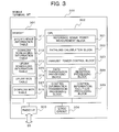
- the femto-cell BS 200 includes a memory 201, a CPU 202, a radio I/F 203, a logic circuit 204, and a wired I/F 205.
- the radio I/F 203 performs transmission and reception of radio signals with mobile terminals.
- the logic circuit 204 performs forward error correction coding and the like.
- the wired I/F 205 performs communication with a network device and neighboring base stations.
- the memory 201 includes an interference information table 211, a downlink scheduling information table 212, an uplink scheduling information table 213, a downlink modulation and coding scheme (MCS) table 214, and an uplink MCS table 215.
- the interference information table 211 stores the reference signal power and pathloss information.
- the downlink scheduling information table 212 stores scheduling results in the downlink.
- the uplink scheduling information table 213 stores scheduling results in the uplink.
- the downlink MCS table 214 is used for downlink data transmission.
- the uplink MCS table 215 is used for uplink data reception.
- the CPU 202 executes a program.
- the CPU 202 includes an interference measurement block 221, a downlink scheduling mode switching block 222, a downlink scheduler 223, an uplink scheduling mode switching block 224, an uplink scheduler 225, a data transmission processing block 226, a control information transmission processing block 227, a data reception processing block 228, a control information reception processing block 229, and an uplink transmission power control block 230.
- the interference measurement block 221 measures the received interference level of the uplink.
- the downlink scheduler 223 determines the frequency resource assignment, MCS, and the like for data transmission in the downlink.
- the uplink scheduler 225 determines the frequency resource assignment, MCS, and the like for data transmission in the uplink.
- the data transmission processing block 226 processes data to be transmitted to mobile terminals.
- the control information transmission processing block 227 processes control information to be transmitted to mobile terminals, such as scheduling result and uplink data decoding result (ACK/NACK) with respect to each mobile terminal.
- the data reception processing block 228 processes data received from mobile terminals.
- the control information reception processing block 229 processes control information, such as downlink data decoding results (ACK/NACK), received from each mobile terminal.
- the uplink transmission power control block 230 controls the transmission power of each mobile terminal.
- the femto-cell MT 300 includes a memory 301, a CPU 302, a radio I/F 303, and a logic circuit 304.
- the radio I/F 303 performs transmission and reception of radio signals with a base station.
- the logic circuit 304 performs forward error correction coding and the like.
- the memory 301 includes an interference information table 311, a downlink scheduling information table 312, an uplink scheduling information table 313, a downlink MCS table 314, and an uplink MCS table 315.
- the interference information table 311 stores the reference signal power and pathloss information measured by the femto-cell MT 300.
- the downlink scheduling information table 312 stores the scheduling result of the particular mobile terminal in the downlink.
- the uplink scheduling information table 313 stores the scheduling result of the particular mobile terminal in the uplink.
- the downlink MCS table 314 is used for downlink data reception.
- the uplink MCS table 315 is used for uplink data transmission.
- the CPU 302 includes a reference signal power measurement block 321, a pathloss calculation block 322, a transmission power control block 323, a data transmission processing block 326, a data reception processing block 328, and a control information reception processing block 329.
- the reference signal power measurement block 321 calculates the received power level of the reference signal (RS) from the base station.
- the pathloss calculation block 322 calculates the attenuation of radio signal in radio channel (pathloss) from the base station to the particular mobile terminal in the downlink.
- the transmission power control block 323 controls the transmission power of the uplink signal transmitted from the mobile terminal to the base station.
- the data transmission processing block 326 processes data to be transmitted to the base station.
- the control information transmission processing block 327 processes control information to be transmitted to the base station, such as downlink data decoding result (ACK/NACK).
- the data reception processing block 328 processes data received from the base station.
- the control information reception processing block 329 processes control information received from the base station, such as scheduling result and uplink data decoding result (ACK/NACK) with respect to the particular mobile terminal.
- the influence of interference is different depending on the installation location of the femto-cell BS 200 with respect to the macro-cell BS 100.
- the influence of interference in the downlink will be described with reference to FIGS. 4 and 5 .
- FIG. 4 shows the arrangement in which the femto-cell BS 200 is located close to the macro-cell BS 100. Referring to FIG. 4 , there is shown the influence of interference received by a macro-cell MT 400-1 that is located close to the cell center, a macro-cell MT 400-2 that is located close to the cell edge, and the femto-cell MT 300.
- the macro-cell MT 400-1 which is located close to the cell center, is in the vicinity of the femto-cell BS 200.
- the interference power from the femto-cell BS 200 is relatively large.
- the macro-cell MT 400-1 is in the vicinity of the macro-cell BS 100.
- the received signal power in the macro-cell MT 400-1 from the macro-cell BS 100 is sufficiently large. For this reason, it is considered that the index of communication quality called Signal-to-Interference and Noise Ratio (SINR) may not be significantly degraded.
- SINR Signal-to-Interference and Noise Ratio
- the macro-cell MT 400-2 which is located close to the cell edge, is located far from the macro-cell BS 100.
- the received signal power from the macro-cell BS 100 is relatively small in the macro-cell MT 400-2 that is located close to the cell edge.
- the macro-cell MT 400-2 is located far from the femto-cell BS 200.
- the interference power from the femto-cell BS 200 is small in the macro-cell MT 400-2 that is located close to the cell edge. For this reason, it is considered that SINR may not be significantly degraded.
- the femto-cell MT 300 is in the vicinity of the macro-cell BS 100.
- the interference power from the macro-cell BS 100 is relatively large.
- the femto-cell MT 300 is also located in the vicinity of the femto-cell BS 200.
- the received signal power from the femto-cell BS 200 is sufficiently large. For this reason, it is considered that SINR may not be significantly degraded.
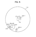
- FIG. 5 shows the arrangement in which the femto-cell BS 200 is installed close to the cell edge. Referring to FIG. 5 , there is shown the influence of interference received by the macro-cell MT 400-1 that is located close to the cell center, the macro-cell MT 400-2 that is located close to the cell edge, and the femto-cell MT 300.
- the macro-cell MT 400-1 which is located close to the cell center, is in the vicinity of the macro-cell BS 100. Thus, the received signal power from the macro-cell BS 100 is sufficiently large. Further, the macro-cell MT 400-1 is located far from the femto-cell BS 200. Thus, the interference power from the femto-cell BS 200 is relatively small. For this reason, it is considered that SINR is large and the communication quality is good.
- the macro-cell MT 400-2 which is located close to the cell edge, is located far from the macro-cell BS 100. Thus, the received signal power from the macro-cell BS 100 is relatively small. Further, the macro-cell MT 400-2 is located in the vicinity of the femto-cell BS 200. Thus, the interference power from the femto-cell BS 200 is large. For this reason, it is considered that SINR is significantly degraded.
- the femto-cell MT 300 is located in the vicinity of the femto-cell BS 200. Thus, the received signal power from the femto-cell BS 200 is sufficiently large. Further, the femto-cell MT 300 is located far from the macro-cell BS 100. Thus, the interference power from the macro-cell BS 100 is relatively small. For this reason, it is considered that SINR is large and the communication quality is good.
- the scheduling mode in the femto-cell BS to perform the downlink data transmission to the femto-cell MT is switched according to the interference given to the macro-cell MT.
- the femto-cell BS selects interference mitigation mode as the downlink scheduling mode.
- the femto-cell BS selects high data rate mode as the downlink scheduling mode.
- the scheduling mode will be described in detail below.
- the determination of the magnitude of the interference to the macro-cell MT that is located close to the cell edge can be performed based on the passive interference level measured by the macro-cell MT.
- the macro-cell MT notifies the femto-cell BS of the measured interference level from the femto-cell BS.
- the femto-cell BS determines the downlink scheduling mode based on the magnitude of the interference level notified by the macro-cell MT.
- the macro-cell MT in order to notify the femto-cell BS of the interference level as described above, the macro-cell MT must be connected to the femto-cell BS, or the macro-cell MT notifies the macro-cell BS of the interference level which is then forwarded to the femto-cell BS from the macro-cell BS.
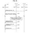
- FIGS. 6 and 9 show the sequence for determining the downlink scheduling mode.
- FIGS. 7 , 8 , and 9 show the process for determining the downlink scheduling mode.
- the macro-cell BS 100 transmits a reference signal (RS) (S601).
- the femto-cell MT 300 causes the reference signal power measurement block 321 to calculate the reference signal received power (RSRP) that is received through the radio I/F 303.
- RSRP reference signal received power
- the femto-cell MT 300 causes the pathloss calculation block 322 to calculate the pathloss between the macro-cell BS 100 and the femto-cell MT 300, by using the received reference signal received power and the reference signal transmission power of the macro-cell BS 100.
- the femto-cell MT 300 notifies the femto-cell BS 200 of the RSRP or pathloss (S602).
- the femto-cell BS 200 stores the RSRP or pathloss information notified by N (N is 1 or more) femto-cell MTs 200 into the interference information table 211.
- the femto-cell BS 200 causes the downlink scheduling switching block 222 to determine the downlink scheduling mode by using the RSRP or pathloss information (S603).
- the femto-cell BS 200 sets the configuration for the data transmission in the downlink if necessary (S604).
- the femto-cell BS 200 transmits the resource assignment information for the downlink data transmission, as downlink scheduling information, to the femto-cell MT 300 (S605).
- the femto-cell BS 200 transmits the downlink data to the femto-cell MT 300 (S606).
- the downlink scheduling mode switching block 222 initializes the number of mobile terminals M, in order to count the number of mobile terminals M with RSRP exceeding a predetermined RSRP threshold (S701). If there is a mobile terminal with RSRP equal to or greater than a threshold ThRsrpDL (YES in S702), the downlink scheduling mode switching block 222 adds 1 to the number of mobile terminals M (S703).
- the processes of step 702 and step 703 are performed with respect to N femto-cell MTs that have notified the femto-cell BS 200 of RSRP.
- the downlink scheduling mode switching block 222 determines that the femto-cell MT 300 and the femto-cell BS 200 are located close to the cell center as shown in FIG. 4 .
- the downlink scheduling mode switching block 222 selects the high data rate mode as the downlink scheduling mode (S705).
- the downlink scheduling mode switching block 222 determines that the femto-cell MT 300 and the femto-cell BS 200 are located close to the cell edge as shown in FIG. 5 .
- the downlink scheduling mode switching block 222 selects the interference mitigation mode as the downlink scheduling mode (S706).
- the downlink scheduling mode switching block 222 initializes the number of mobile terminals M, in order to count the number of mobile terminals M with pathloss exceeding a predetermined threshold (S801). If there is a mobile terminal with pathloss less than a threshold ThPathLossDL (YES in S802), the downlink scheduling mode switching block 222 adds 1 to the number of mobile terminals M (S803).
- the processes of step 802 and step 803 are performed with respect to N femto-cell MTs that have notified the femto-cell BS of pathloss.
- the downlink scheduling mode switching block 222 determines that the femto-cell MT 300 and the femto-cell BS 200 are located close to the cell center as shown in FIG. 4 .
- the downlink scheduling mode switching block 222 selects the high data rate mode as the downlink scheduling mode (S805).
- the downlink scheduling mode switching block 222 determines that the femto-cell MT 300 and the femto-cell BS 200 are located close to the cell edge as shown in FIG. 5 .
- the downlink scheduling mode switching block 222 selects the interference mitigation mode as the downlink scheduling mode (S806).
- the downlink scheduling mode is determined based on RSRP or pathloss with respect to a single macro-cell BS. However, the downlink scheduling mode may also be determined based on RSRP or pathloss with respect to a plurality of macro-cell BSs.
- the femto-cell MT 300 measures RSRP or pathloss.
- the femto-cell BS 200 may perform the downlink reception function and measurement of RSRP or pathloss.
- the downlink scheduling mode is selected by using RSRP with respect to the macro-cell.
- the relative value of RSRP with respect to the macro-cell, to RSRP with respect to the femto-cell may also be used as the selection criterion.
- the downlink scheduling mode is determined based on the pathloss that is notified by the femto-cell MT 300 to the femto-cell BS 200.
- it is also possible to determine the downlink scheduling mode by using the pathloss calculated by the femto-cell BS 200 using the RSRP that is notified by the femto-cell MT 300 to the femto-cell BS 200, and using the reference signal transmission power of the macro-cell BS 100.
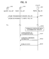
- FIG. 9 there is shown the procedure for determining the state of the interference to the macro-cell MT from the femto-cell BS, based on the uplink interference information measured by the femto-cell BS.
- the macro-cell MT 400 performs an uplink transmission to the macro-cell BS 100 (S901).
- the uplink transmission by the macro-cell MT 400 is received as interference by the femto-cell BS 200.
- the femto-cell BS 200 causes the interference measurement block 221 to calculate the interference power level from a plurality of macro-cell MTs 400 for each of the divided frequency blocks of the used frequency band.
- the frequency block is a resource block (RB) which is the smallest unit of the frequency resource assignment in E-UTRA.
- the femto-cell BS 200 causes the downlink scheduling mode switching block 222 to determine the downlink scheduling mode by using the calculated interference power level from the macro-cell MT 400 (S902). Then, the femto-cell BS 200 sets the configuration for the downlink data transmission if necessary (S903). The femto-cell BS 200 transmits the resource assignment information for the downlink data transmission, as downlink scheduling information, to the femto-cell MT 300 (S904). The femto-cell BS 200 transmits the downlink data to the femto-cell MT 300 (S905).
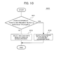
- the downlink scheduling mode determination step 902 that is performed by the downlink scheduling mode switching block 222 of the femto-cell BS 200, based on the uplink interference power level from the macro-cell MT 400.
- the downlink scheduling mode switching block 222 determines that the femto-cell MT 300 and the femto-cell BS 200 are located close to the cell center as shown in FIG. 4 .
- the downlink scheduling mode switching block 222 of the femto-cell BS 200 selects the high data rate mode as the downlink scheduling mode (S102).
- the downlink scheduling mode switching block 222 of the femto-cell BS 200 determines that the femto-cell MT 300 and the femto-cell BS 200 are located close to the cell edge as shown in FIG. 5 .
- the downlink scheduling mode switching block 222 of the femto-cell BS 200 selects the interference mitigation mode as the downlink scheduling mode (S103).
- the determination of the downlink scheduling mode described in FIGS. 6 to 10 may be performed at the time when the femto-cell BS 200 is installed, or may be performed periodically.
- the interference mitigation mode is selected as the downlink scheduling mode, the interference to the macro-cell MT 400 from the femto-cell BS 200 is not a problem, when the macro-cell MT 400 is not present in the vicinity of the femto-cell BS 200, or when the macro-cell 400 that was in the vicinity of the femto-cell BS 200 is moved far away.
- the high data rate mode may be selected (redetermined) according to FIG. 11 .
- FIG. 11 there is shown the flow of the downlink scheduling mode redetermination process that is performed by the downlink scheduling mode switching block 222 of the femto-cell BS 200, based on the uplink interference power level from the macro-cell MT 400.
- the interference mitigation mode is selected as the downlink scheduling mode (YES in S111)
- the downlink scheduling mode switching block 222 of the femto-cell BS 200 obtains the uplink interference power level for each frequency block from the interference measurement block 221 (S112).
- the downlink scheduling mode switching block 222 of the femto-cell BS 200 determines that the macro-cell MT 400 is not present in the vicinity of the femto-cell BS 200.
- the downlink scheduling mode switching block 222 of the femto-cell BS 200 selects the high data rate mode as the downlink scheduling mode (S114), and ends the redetermination process. If NO in step 111 or in step 113, the downlink scheduling mode switching block 222 of the femto-cell BS 200 ends the redetermination process, and continues the interference mitigation mode.
- the downlink scheduling mode redetermination process shown in FIG. 11 may be performed after the downlink scheduling mode determination process shown in FIGS. 7 , 8 , and 10 , or may be performed periodically.
- the downlink scheduling mode will be described in detail with reference to FIGS. 12 to 20 .
- a first embodiment that uses the downlink scheduling mode properly will be described with reference to FIGS. 12 to 15B .
- the high data rate mode it is intended to increase the rate due to the frequency selectivity gain, by assigning frequency resources that are continuous in the frequency domain as downlink communication resources.
- the interference mitigation mode it is intended to distribute the influence of interference to the macro-cell MT 400 from the femto-cell BS 200, by assigning frequency resources distributed in the frequency domain as downlink communication resources.
- the assignment of the frequency resources used for the downlink data transmission to the femto-cell MT 300 is performed by the downlink scheduler 223 of the femto-cell BS 200 according to the downlink scheduling mode determined by the downlink scheduling mode switching block 222.
- the following description will focus on the frequency resource assignment method in the high data rate mode and in the interference mitigation mode, respectively, using a resource allocation (RA) type defined in E-UTRA.
- RA resource allocation
- the femto-cell BS 200 notifies the femto-cell MT 300 of the RA type and assigned frequency resources.
- the downlink data transmission is performed according to the downlink scheduling information notified to the femto-cell MT 300.
- the frequency resource assignment using RA Type 2-Localized which is used in the high data rate mode, will be described with reference to FIG. 12 .
- the horizontal axis represents the frequency, in which the full width is the bandwidth of the system.
- the bandwidth of the system is divided into the smallest unit of frequency resources, which is called RB.
- RA Type 2-Localized a single RB or continuous RBs are assigned to a mobile terminal.
- 12 RBs are assigned to a terminal #1
- 6 RBs are assigned to a terminal #2
- 9 RBs are assigned to a terminal #3.
- the frequency selectivity gain can be obtained by centrally assigning RBs in a subband with a good radio channel quality by using RA Type 2-Localized. As a result, the communication quality can be improved.
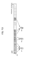
- RA Type 0 The frequency resource assignment using RA Type 0, which is used in the high data rate mode, will be described with reference to FIG. 13 .
- E-UTRA as shown in FIG. 13 , a plurality of continuous RBs constitutes a resource block group (RBG).
- RBG resource block group
- frequency resources are assigned to a mobile terminal in the unit of RBG.
- continuous RBGs may be assigned as the case of the terminals #1 and #2 shown in FIG. 13 , or separate RBGs may be assigned as the case of the terminal #3 shown in FIG. 13 .
- the frequency selectivity gain can be obtained by centrally assigning RBs in a subband with a good radio channel quality by using RA Type 0. As a result, the communication quality can be improved.
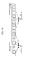
- RA Type 1 The frequency resource assignment using RA Type 1, which is used in the interference mitigation mode, will be described with reference to FIG. 14 .
- E-UTRA as shown in FIG. 14 , a plurality of separate RBGs constitutes an RBG subset. In FIG. 14 , three RBG subsets are present.
- RA Type 1 frequency resources in one of the RBG subsets are assigned to a mobile terminal in the RB unit.
- a subset 0 is assigned to the terminal #1
- a subset 2 is assigned to the terminal #2.
- up to three RBs can be assigned by selecting RBs from the same RBG.
- the macro-cell MT 400 receiving the influence of interference is expected to be different for each RB by assigning distributed RBs by using RA Type 1.
- the influence of interference given by the femto-cell BS 200 is distributed.
- the degradation of communication quality due to the interference can be suppressed in the macro-cell MT 400.
- FIG. 15A shows the frequency resource in the logical domain
- FIG. 15B shows the frequency resource in the physical domain, in which the horizontal axis is the frequency.
- RA Type 2-Distributed the specification of frequency resources is made in the logical domain.
- the resource assignment in the logical domain is performed as shown in FIG. 15A , which is the same as the resource assignment in RA Type 2-Localized.
- Virtual RB is mapped to physical RB that is used for data transmission, by using a predetermined permutation pattern. In the mapping from virtual RB to physical RB, as shown in FIGS.
- continuous virtual RBs are mapped to separate physical RBs.
- separate physical RBs can be assigned in the frequency domain by assigning continuous virtual RBs.
- the macro-cell MT 400 receiving the influence of interference is expected to be different for each RB.
- the influence of interference given by the femto-cell BS 200 is distributed. As a result, the degradation of communication quality due to the interference can be suppressed in the macro-cell MT 400.
- a second embodiment that uses the downlink scheduling mode properly will be described with reference to FIGS. 16 and 17 .
- the second embodiment in the high data rate mode, it is intended to increase the rate due to the frequency sensitivity gain, by not applying frequency hopping to the frequency resources assigned as the downlink communication resources.
- the interference mitigation mode it is intended to distribute the influence of interference to the macro-cell MT 400 from the femto-cell BS 200, by applying frequency hopping to the frequency resources assigned as the downlink communication resources.
- the frequency resource assignment for HARQ transmission which is used for the downlink data transmission to the femto-cell MT 300, is performed by the downlink scheduler 223 of the femto-cell BS 200 according to the downlink scheduling mode determined by the downlink scheduling mode switching block 222.
- the assigned frequency resources are notified, as the downlink scheduling information, by the femto-cell BS 200 to the femto-cell MT 300 in sequence 605 of FIG. 6 and in sequence 904 of FIG. 9 .
- the downlink data transmission is performed according to the downlink scheduling information notified to the femto-cell MT 300.
- the frequency resource assignment without applying frequency hopping which is used in the high data rate mode, will be described with reference to FIG. 16 .
- the number n on the left side represents the number of times HARQ transmitted, and the horizontal axis represents the frequency.
- RBs assigned to the terminal #1 in the first HARQ transmission are the same as those in the subsequent transmissions.
- the frequency sensitivity gain can be obtained by assigning RBs in a subband with a good channel radio channel quality for each HARQ retransmission. As a result, the communication quality can be improved.
- the same RBs are assigned for each HARQ transmission. However, the assigned RBs are not necessarily exactly the same and it is enough to assign RBs in the same subband.
- the frequency resource assignment to which frequency hopping is applied, which is used in the interference mitigation mode, will be described with reference to FIG. 17 .
- the number n on the left side represents the number of times HARQ is transmitted, and the horizontal axis represents the frequency.
- RBs assigned to the terminal #1 are different for each of the HARQ transmissions (1, 2, 3, and 4).
- the macro-cell MT 400 receiving the influence of interference is expected to be different in each HARQ retransmission.
- the influence of interference given by the femto-cell BS 200 is distributed. As a result, the degradation of communication quality due to the interference can be suppressed in the macro-cell MT 400.
- a third embodiment that uses the downlink scheduling mode properly will be described with reference to FIGS. 18 to 20 .
- the third embodiment in the high data rate mode, it is intended to increase the rate by improving the received SINR in the femto-cell MT 300 by using a high power spectrum density for the downlink data transmission.
- the interference mitigation mode it is intended to reduce the received interference power spectrum density given by the femto-cell BS 200 to the macro-cell MT 400, by using a low power spectrum density for the downlink data transmission.
- Setting of the power spectrum density used for the downlink transmission to the femto-cell MT 300 is performed by the control information transmission processing block 227 according to the downlink scheduling mode determined by the downlink scheduling mode switching block 222 of the femto-cell BS 200.
- the power spectrum density information is notified, as the transmission mode configuration, by the femto-cell BS 200 to the femto-cell MT 300 in sequence 604 of FIG. 6 or in sequence 903 of FIG. 9 .
- the downlink data transmission is performed according to the power spectrum density that is notified by the femto-cell BS 200 to the femto-cell MT 300 as described above.
- FIG. 18 there is shown the relationship in the high data rate mode between the transmission power spectrum density using a high power spectrum density PwrDensityHighDL, and the assigned frequency resource to a certain femto-cell MT 300.
- the femto-cell BS 200 performs the downlink data transmission by using the high transmission power spectrum density.
- the received SINR in the femto-cell MT 300 is improved.
- the communication quality can be improved.
- FIG. 19 there is shown the relationship in the interference mitigation mode between the transmission power spectrum density using a low power spectrum density PwrDensityLowDL, and the assigned frequency resource to a certain femto-cell MT 300.
- PwrDensityLowDL is less than PwrDensityHighDL.
- the femto-cell BS 200 performs the downlink data transmission by using the low transmission power spectrum density.
- the received interference level in the macro-cell MT 400 from the femto-cell BS 200 is reduced.
- the degradation of communication quality due to the interference can be suppressed in the macro-cell MT 400.
- a modulation and coding scheme (MCS) table will be described with reference to FIG. 20 .
- a downlink MCS table 214/314 includes an MCS index 2141 and a subcarrier modulation scheme 2142.
- the PHY packet size is defined according to the MCS and the number of assigned RBs, based on which the coding rate of forward error correction (FEC) can be calculated.
- a coding rate 2143 in FIG. 20 represents the approximate value.
- the downlink scheduler 223 of the femto-cell BS 200 selects an MCS from the downlink MCS table 214.
- the downlink scheduler 223 stores the MCS index of the selected MCS in the downlink scheduling information table 212.
- the femto-cell BS 200 transmits the downlink scheduling information to the femto-cell MT 300.
- the femto-cell MT 300 receives the data, by referring to the MCS index of the downlink scheduling information and to the downlink MCS table 314.
- the received SINR in the femto-cell MT 300 is increased in the high data rate mode.
- the femto-cell BS 200 selects a high MCS for the downlink data transmission to the femto-cell MT 300.
- the femto-cell BS 200 performs the downlink data transmission by using a low transmission power spectrum density.
- the received SINR is reduced in the femto-cell MT 300.
- the femto-cell BS 200 selects a low MCS in order to increase the probability of success of decoding.
- the MCS used for the downlink data transmission is notified, as the downlink scheduling information, by the femto-cell BS 200 to the femto-cell MT 300 in sequence 605 of FIG. 6 or in sequence 904 of FIG. 9 .
- the PHY packet size is reduced and the data rate is reduced.
- the data rate can be maintained by increasing the number of RBs assigned to the femto-cell MT 300. By increasing the number of assigned RBs, it is possible to prevent the PHY packet size from being reduced, thereby preventing the data rate reduction, even when a low MCS is selected.
- the assigned frequency resource width (the number of RBs) shown in FIG. 19 is greater than the assigned frequency resource width (the number of RBs) shown in FIG. 18 .
- the received SINR in the femto-cell MT 300 is increased.
- the data rate can be increased by performing spatial multiplexing (SM) with multipleinput multiple-output (MIMO) for the downlink data transmission from the femto-cell BS 200 to the femto-cell MT 300.
- SM spatial multiplexing
- MIMO multipleinput multiple-output
- the received SINR is degraded in the femto-cell MT 300.
- the communication quality can be improved by performing transmission diversity with space-time block code (STBC), and the like, for the downlink data transmission from the femto-cell BS 200 to the femto-cell MT 300.
- STBC space-time block code
- first to third embodiments are not exclusive of each other, and a plurality of embodiments can be used in combination.
- the influence of interference in the uplink will be described using again Figs 4 and 5 .
- the influence of the uplink interference received by the macro-cell BS 100 and by the femto-cell 200 will be described with reference to FIG. 4 .
- the uplink transmission power control policy the power spectrum density of the received signal in the macro-cell BS 100 from the macro-cell MT 400 is controlled to be constant between the macro-cell MTs 400.
- the uplink transmission power setting is performed according to the power spectrum density of the received interference from the nearby macro-cell MTs 400.
- the transmission power spectrum density of the femto-cell MT 300 is increased, in order to ensure stable communication quality (received SINR) in the femto-cell BS 200.
- the received power spectrum density of the interference given by the nearby macro-cell MTs 400 to the femto-cell BS 200 is small, the transmission power spectrum density of the femto-cell MT 300 is reduced.
- the power spectrum density of the received signal in the macro-cell BS 100 from the macro-cell MTs is constant, independent of the positions of the macro-cell MTs (400-1, 400-2). Further, because the femto-cell is located in the vicinity of the macro-cell BS 100, the transmission power spectrum density of the femto-cell MT 300 is relatively small. When the communication range in the femto-cell is sufficiently small, the transmission power spectrum density of the femto-cell MT 300 has a small variation in the used bandwidth of the system. For this reason, the variation of the received SINR in the macro-cell BS 100 can be considered to be small in the used bandwidth of the system.
- the power spectrum density of the received signal in the femto-cell BS 200 from the femto-cell MT 300 has a small variation in the used bandwidth of the system. Further, because the femto-cell BS 200 is located in the vicinity of the macro-cell BS 100, the power spectrum density of the received interference from the macro-cell MTs is constant in the femto-cell BS 200, independent of the positions of the macro-cell MTs (400-1, 400-2). For this reason, the variation of the received SINR is considered to be small in the used bandwidth of the system.
- the influence of the uplink interference received by the macro-cell BS 100 and by the femto-cell BS 200 will be described with reference to FIG. 5 .
- the power spectrum density of the received signal in the macro-cell BS 100 from the macro-cell MTs is constant, independent of the positions of the macro-cell MTs (400-1, 400-2). This is similar to the case shown in FIG. 4 .
- the femto-cell is located far from the macro-cell BS 100 and in the vicinity of the macro-cell MT 400-2 in which the transmission power spectrum density is high.
- the transmission power spectrum density of the femto-cell MT 300 needs to be increased to a relatively large value.
- the received interference in the macro-cell BS 100 is considered to be substantially unchanged from that in FIG. 4 .
- the transmission power spectrum density of the femto-cell MT 300 has a small variation in the used bandwidth of the system. For this reason, the variation of the received SINR in the macro-cell BS 100 is considered to be small in the used bandwidth of the system.
- the variation of the power spectrum density of the received signal in the femto-cell BS 200 from the femto-cell MT 300 is small in the used bandwidth of the system. Further, in the femto-cell BS 200, the power spectrum density of the received interference from the macro-cell MT varies depending on the macro-cell MT which is the interference source. In the macro-cell MT 400-1 that is located close to the cell center, the transmission power spectrum density is small and the channel attenuation to the femto-cell BS 200 is large. Thus, the power spectrum density of the interference received by the femto-cell BS 200 is reduced.
- the transmission power spectrum density is large and the channel attenuation to the femto-cell BS 200 is small.
- the power spectrum density of the interference received by the femto-cell BS 200 is increased.
- the variation of the received SINR is considered to be large in the used bandwidth of the system.
- the influence of interference by the macro-cell MT 400-2 that is located close to the cell edge is considered to be large.
- the uplink scheduling mode is switched in the femto-cell BS to perform the uplink data transmission from the femto-cell MT, according to the interference given by the macro-cell MT.
- the femto-cell BS selects the frequency diversity mode as the uplink scheduling mode.
- the femto-cell BS selects the time diversity mode as the uplink scheduling mode. The scheduling mode will be described in detail below.
- the uplink scheduling mode is determined by estimating the state of the interference from the macro-cell MT, which will be described with reference to FIG. 21 , 22 , 23 , 24 , and 25 .
- FIGS. 21 and 24 show the sequence for determining the uplink scheduling mode.
- FIG. 22 , 23 , and 25 show the process for determining the uplink scheduling mode.
- the macro-cell BS 100 transmits a reference signal (RS) (S121).
- the femto-cell MT 300 causes the reference signal power measurement block 321 to calculate the power level of the reference signal (RSRP) that is received through the radio I/F 303.
- RSRP reference signal
- the femto-cell MT 300 causes the pathloss calculation block 322 to calculate the pathloss between the macro-cell BS 100 and the femto-cell MT 300, by using the received power level of the reference signal and the transmission power of the reference signal in the macro-cell BS 100.
- the femto-cell MT 300 notifies the femto-cell BS 200 of the calculated RSRP or pathloss (S122).
- the femto-cell BS 200 stores the RSRP or pathloss information that is notified by one femto-cell MT 300 or a plurality of femto-cell MTs 300, into the interference information table 211.
- the femto-cell BS 200 causes the uplink scheduling mode switching block 224 to determine the uplink scheduling mode by using the RSRP or pathloss information (S123). Then, the femto-cell BS 200 sets the configuration for the uplink data transmission if necessary (S124).
- the femto-cell BS 200 transmits the resource assignment information for the uplink data transmission to the femto-cell MT 300 as the uplink scheduling information (S125).
- the femto-cell MT 300 transmits the uplink data to the femto-cell BS 200 (S126).
- the femto-cell BS 200 initializes the number of mobile terminals M, in order to count the number of mobile terminals M with RSRP exceeding a predetermined threshold (S131). If there is a mobile terminal with RSRP exceeding a threshold ThRsrpUL (YES in S132), the femto-cell BS 200 adds 1 to the number of mobile terminals M (S133). The processes of step 132 and step 133 are performed with respect to N femto-cell MTs that have notified the femto-cell BS 200 of RSRP.
- the femto-cell BS 200 determines that the femto-cell MT 300 and the femto-cell BS 200 are located close to the cell center as shown in FIG. 4 .
- the femto-cell BS 200 selects the frequency diversity mode as the uplink scheduling mode (S135).
- the femto-cell BS 200 determines that the femto-cell MT 300 and the femto-cell BS 200 are located close to the cell edge as shown in FIG. 5 .
- the femto-cell BS 200 selects the time diversity mode as the uplink scheduling mode (S136).
- the femto-cell BS 200 initializes the number of mobile terminals M, in order to count the number of mobile terminals M with RSRP exceeding a predetermined threshold (S141). If there is a mobile terminal with pathloss less than a threshold ThPathLossUL (YES in S142), the femto-cell BS 200 adds 1 to the number of mobile terminals M (S143).
- step 142 and step 143 are performed with respect to N femto-cell MTs that have notified the femto-cell BS 200 of pathloss. Then, if the ratio of the number of mobile terminals with RSRP less than the threshold ThPathLossUL, to the number of femto-cell MTs that have notified the femto-cell BS 200 of pathloss, M/N, is equal to or greater than a predetermined threshold ThFreqDiv (YES in S144), the femto-cell BS 200 determines that the femto-cell MT 300 and the femto-cell BS 200 are located close to the cell center as shown in FIG. 4 .
- ThFreqDiv YES in S144
- the femto-cell BS 200 selects the frequency diversity mode as the uplink scheduling mode (S145). If M/N is less than the threshold ThFreqDiv (NO in S144), the femto-cell BS 200 determines that the femto-cell MT 300 and the femto-cell BS 200 are located close to the cell edge as shown in FIG. 5 . The femto-cell BS 200 selects the time diversity mode as the uplink scheduling mode (S146).
- the uplink scheduling mode is determined based on RSRP or pathloss with respect to a single macro-cell BS. However, it may also be based on RSRP or pathloss with respect to a plurality of macro-cell BSs.
- the femto-cell MT 300 measures RSRP or pathloss.
- the femto-cell BS 200 may perform the downlink reception function and measurement of RSRP or pathloss.
- the downlink scheduling mode is selected using RSRP with respect to the macro-cell.
- the relative value of RSRP with respect to the macro-cell, to RSRP with respect to the femto-cell may also be used as the selection criterion.
- the uplink scheduling mode is determined based on the pathloss notified by the femto-cell MT 300 to the femto-cell BS 200. However, it is also possible to determine the uplink scheduling mode, by using the pathloss calculated by the femto-cell BS 200 using the RSRP notified by the femto-cell MT 300 to the femto-cell BS 200, and using the transmission power of the reference signal in the macro-cell BS 100.
- the macro-cell MT 400 performs an uplink transmission to the macro-cell BS 100.
- the uplink transmission by the macro-cell MT 400 is received by the femto-cell BS 200 as interference (S151).
- the femto-cell BS 200 causes the interference measurement block 221 to calculate the interference power level from a plurality of macro-cell MTs 400, for each of the divided frequency blocks of the used frequency band.
- the frequency block is a resource block (RB) which is the smallest unit of the frequency resource assignment in E-UTRA.
- the femto-cell BS 200 causes the uplink scheduling mode switching block 224 to determine the uplink scheduling mode by using the calculated interference power level from the macro-cell MT 400 (S152). Then, the femto-cell BS 200 sets the configuration for the uplink data transmission if necessary (S153). The femto-cell BS 200 transmits the resource assignment information for the uplink data transmission to the femto-cell MT 300 as the uplink scheduling information (S154). The femto-cell MT 300 transmits the uplink data to the femto-cell BS 200 (S155).
- RB resource block
- the flow of the uplink scheduling mode determination process S152 that is performed by the uplink scheduling mode switching block 224 of the femto-cell BS 200, based on the uplink interference power level from the macro-cell MT 400.
- the femto-cell BS 200 determines that the femto-cell MT 300 and the femto-cell BS 200 are located close to the cell center as shown in FIG. 4 .
- the femto-cell BS 200 selects the frequency diversity mode as the uplink scheduling mode (S162).
- the femto-cell BS 200 determines that the femto-cell MT 300 and the femto-cell BS 200 are located close to the cell edge as shown in FIG. 5 .
- the femto-cell BS 200 selects the time diversity mode as the uplink scheduling mode (S163).
- the uplink scheduling mode is selected based on the uplink interference power for each frequency block.
- the difference of the uplink interference power between frequency blocks may also be used as the selection criterion. For example, if the uplink interference power difference between any frequency blocks is equal to or greater than a predetermined threshold, the time diversity mode is selected as the uplink scheduling mode, and otherwise the frequency diversity mode is selected.
- the uplink scheduling mode determination described in FIGS. 21 to 25 may be performed at the time when the femto-cell BS 200 is installed or may be performed periodically.
- the frequency diversity mode may be selected (redetermined) according to FIG. 26 .
- FIG. 26 there is shown the flow of the uplink scheduling mode redetermination process that is performed by the uplink scheduling mode switching block 224 of the femto-cell BS 200, based on the uplink interference power level from the macro-cell MT 400.
- the femto-cell BS 200 obtains the uplink interference power level for each frequency block, from the interference measurement block 221 (S172).
- the femto-cell BS 200 determines that the macro-cell MT 400 is not in the vicinity of the femto-cell BS 200.
- the femto-cell BS 200 selects the frequency diversity mode as the uplink scheduling mode (S174), and ends the redetermination process. If NO in step 171 or in step 173, the femto-cell BS 200 ends the redetermination process.
- the uplink scheduling mode redetermination process shown in FIG. 26 may be performed after the uplink scheduling mode determination process shown in FIGS. 22 , 23 , and 25 , or may be performed periodically.
- the uplink scheduling mode will be described in detail with reference to FIGS. 27 to 30 .
- the uplink data transmission of the femto-cell MT 300 is performed by using a low power spectrum density, assuming that the macro-cell MT 400-1 having low power spectrum density is present in the vicinity of the femto-cell as shown in FIG. 4 .
- the uplink data transmission of the femto-cell MT 300 is performed by using a high power spectrum density, assuming that the channel attenuation from the femto-cell to the macro-cell BS 100 is large as the case shown in FIG. 5 .
- the power spectrum density used for the uplink data transmission of the femto-cell MT 300 is determined by the uplink transmission power control block 230, according to the uplink scheduling mode determined by the uplink scheduling mode switching block 224 of the femto-cell BS 200. Then, the determined uplink power spectrum density is forwarded to the control information processing block 227.
- the power spectrum density information is notified, as the configuration of the transmission mode, by the femto-cell BS 200 to the femto-cell MT 300 in step 124 of FIG. 21 or in step 153 of FIG. 24 .
- the power spectrum density information is notified, as the scheduling information such as the transmission power command, by the femto-cell BS 200 to the femto-cell MT 300 in step 125 of FIG. 21 or in step 154 of FIG. 24 .
- the uplink data transmission in step 126 of FIG. 21 or in step 155 of FIG. 24 is performed, by using the transmission power determined by the transmission power control block 323 according to the power spectrum density information that is notified to the femto-cell MT 300 as described above.
- the frequency diversity mode reduces the power spectrum density, increases the frequency resource width (the number of assigned RBs), and reduces the MCS (in the direction from 64QAM to QPSK).
- FIG. 28 there is shown the relationship in the time diversity mode between the target received power spectrum density using a high power spectrum density PwrDensityHighUL, and the assigned frequency resource to a certain femto-cell MT 300.
- PwrDensityHighUL is greater than PwrDensityLowUL.
- the time diversity mode increases the power spectrum density, reduces the frequency resource width (the number of assigned RBs), and increases the MCS.
- the uplink MCS table 215/315 includes an MCS index 2151 and a subcarrier modulation scheme 2152.
- the PHY packet size is defined according to the MCS and the number of assigned RBs, based on which the coding rate of forward error correction (FEC) can be calculated.
- FEC forward error correction
- a coding rate 2153 shown in FIG. 29 represents the approximate value.
- the uplink scheduler 225 of the femto-cell BS 200 selects an MCS from the uplink MCS table 215.
- the uplink scheduler 225 stores the MCS index of the selected MCS in the uplink scheduling information table 213.
- the femto-cell BS 200 transmits the uplink scheduling information to the femto-cell MT 300.
- the femto-cell MT 300 transmits the uplink data by referring to the MCS index of the uplink scheduling information and to the uplink MCS table 315.
- the MCS used for the uplink data transmission is notified, as the uplink scheduling information, by the femto-cell BS 200 to the femto-cell MT 300 in step 125 of FIG. 21 or in step 154 of FIG. 24 .
- the target received power spectrum density is low in the frequency diversity mode.
- a low MCS can be selected.
- the PHY packet size is reduced and the data rate is reduced.
- the data rate can be maintained by increasing the number of RBs assigned to the femto-cell MT 300. Even if a low MCS is selected, the PHY packet size is not reduced by increasing the number of assigned RBs, thereby preventing the reduction in the data rate.
- the target received power spectrum density is high in the time diversity mode.
- a high MCS can be selected.
- the transmission data size per RB is larger than when a low MCS is selected.
- the number of assigned RBs can be reduced.
- the assigned frequency resource width (the number of RBs) shown in FIG. 28 is greater than the assigned frequency resource width (the number of RBs) shown in FIG. 27 .
- the femto-cell arrangement shown in FIG. 5 is assumed in the selection of the time diversity mode. In this case, the received SINR in the femto-cell BS 200 varies in the frequency domain.
- RBs are centrally assigned in a subband with a good channel state, in order to obtain the frequency selectivity gain, while avoiding the interference from the macro-cell MT 400-2 that is located in the vicinity of the femto-cell.
- the MCS used for the uplink data transmission to the femto-cell MT 300 is determined by the uplink scheduler 225 of the femto-cell BS 200, according to the uplink scheduling mode determined by the uplink scheduling mode switching block 224.
- the determined MCS is notified, as the uplink scheduling information, by the femto-cell BS 200 to the femto-cell MT 300 in step 125 of FIG. 21 or in step 154 of Fig 24 .
- the uplink data transmission in step 126 of FIG. 21 and in step 155 of FIG. 25 is performed according to the uplink scheduling information that is notified by the femto-cell BS 200 to the femto-cell MT 300 as described above.
- a fifth embodiment that uses the uplink scheduling mode properly will be described with reference to FIG. 30 .
- the number of HARQ transmissions is reduced in the frequency diversity mode, and the number of HARQ transmissions is increased in the time diversity mode.
- the femto-cell MT 300 performs the first HARQ transmission in a subframe 2, the second HARQ transmission in a subframe 10, the third HARQ transmission in a subframe 18, and the fourth HARQ transmission in a subframe 26.
- the femto-cell MT 300 performs the HARQ transmission every eight subframes.
- the femto-cell MT 300 stops the subsequent HARQ transmissions.
- the femto-cell arrangement shown in FIG. 4 is assumed in the selection of the frequency diversity mode. At this time, the variation of the received SINR in the femto-cell BS 200 is small. In such an environment, the time diversity effect that can be obtained by increasing the number of HARQ transmissions is likely to be small. Thus, the reduction in the number of HARQ transmissions reduces the time delay from the start of the uplink data transmission to the success of decoding.
- the number of HARQ transmissions can be reduced by selecting a low MCS.
- a low MCS When a low MCS is selected, the SINR required for the success of decoding is reduced.
- the probability of success of decoding in each HARQ transmission is higher with a low MCS than that with a high MCS.
- the MCS is selected so as to achieve a predetermined (for example, 1%) packet error rate (PER) in the first HARQ transmission (subframe 2 in FIG. 30 ).
- a predetermined for example, 1%) packet error rate (PER) in the first HARQ transmission (subframe 2 in FIG. 30 ).
- the femto-cell arrangement shown in FIG. 4 is assumed in the selection of the time diversity mode.
- the received SINR varies in the femto-cell BS 200.
- the time diversity effect can be obtained by increasing the number of HARQ transmissions.
- the variation of the received SINR can be absorbed by HARQ to realize stable data transmission.
- the number of HARQ transmissions can be increased by selecting a high MCS.
- a high MCS When a high MCS is selected, the SINR required for the success of decoding is increased.
- the probability of success of decoding in each HARQ transmission is lower with a high MCS than that with a low MCS.
- the MCS is selected so as to achieve a predetermined (for example, 1%) packet error rate (PER) in the fourth HARQ transmission (subframe 26 in FIG. 30 ).
- PER packet error rate
- the MCS used for the uplink data transmission to the femto-cell MT 300 is determined by the uplink scheduler 225 of the femto-cell BS 200, according to the uplink scheduling mode determined by the uplink scheduling mode switching block 224.
- the determined MCS is notified, as the uplink scheduling information, by the femto-cell BS 200 to the femto-cell MT 300 in step 125 of FIG. 21 or in step 154 of FIG. 24 .
- the uplink data transmission in step 126 of FIG. 21 and in step 155 of FIG. 24 is performed according to the uplink scheduling information notified to the femto-cell MT 300.
- FIGS. 17 and 16 are diagrams showing the presence or absence of frequency hopping of the downlink, but "downlink” is replaced with “uplink” in the following description.
- the influence of interference from the macro-cell MT 400 to the femto-cell BS 200 is distributed by applying frequency hopping to the frequency resource assigned as the uplink communication resource.
- the frequency diversity mode as described with reference to FIG. 4 , the variation of the received SINR in the femto-cell BS 200 is small.
- frequency hopping is not applied to the frequency resource assigned as the downlink communication resource. In the following description, it is assumed that the frequency hopping is performed for each HARQ transmission.
- the assignment of the frequency resource used for the uplink data transmission to the femto-cell MT 300, as well as the determination of whether frequency hopping is applied or not, are performed by the uplink scheduler 225 of the femto-cell BS 200 according to the uplink scheduling mode determined by the uplink scheduling mode switching block 224.
- the assigned frequency resource is notified, as the uplink scheduling information, by the femto-cell BS 200 to the femto-cell MT 300 in step 125 of FIG. 21 or in step 154 of FIG. 24 .
- the uplink data transmission in step 126 of FIG. 21 or in step 155 of FIG. 24 is performed according to the uplink scheduling information that is notified by the femto-cell BS 200 to the femto-cell MT 300 as described above.
- the frequency resource assignment to which frequency hopping is applied which is used in the time diversity mode, will be described with reference to FIG. 17 .
- RBs assigned to the terminal #1 are different for each of the HARQ transmissions (1, 2, 3, and 4).
- the macro-cell MT 400 giving the influence of interference to the communication of the particular femto-cell MT is expected to be different for each HARQ transmission.
- the influence of interference from the macro-cell 400 is distributed. As a result, the degradation of communication quality due to the interference can be suppressed in the femto-cell.
- RBs assigned to the terminal #1 are the same in the first HARQ transmission (1 in FIG. 16 ) and in the subsequent HARQ transmissions (2, 3, and 4 of FIG. 16 ).
- the same RBs are assigned to the individual HARQ transmissions.
- the same RBs are not necessarily assigned, and it is enough to assign RBs in the same subband.
- frequency hopping may be applied if the frequency selectivity gain is not expected in the frequency diversity mode.
- FIGS. 12 to 15B are diagrams showing the frequency resource assignment of the downlink, but "downlink” is replaced with “uplink” in the following description.
- the frequency diversity mode in the frequency diversity mode, it is intended to increase the rate due to the frequency selectivity gain by assigning frequency resources that are continuous in the frequency domain as uplink communication resources.
- the influence of interference from the macro-cell MT 400 to the femto-cell BS 200 is distributed by assigning frequency resources distributed in the frequency domain.
- the assignment of frequency resources used for the uplink data transmission to the femto-cell MT 300 is performed by the uplink scheduler 225 of the femto-cell BS 200, according to the uplink scheduling mode determined by the uplink scheduling mode switching block 224.
- the assigned frequency resources are notified, as the uplink scheduling information, by the femto-cell BS 200 to the femto-cell MT 300 in step 125 of FIG. 21 or in step 154 of FIG. 24 .
- the uplink data transmission in step 126 of FIG. 21 or in step 155 of FIG. 24 is performed according to the uplink scheduling information notified to the femto-cell MT 300.
- the frequency resource assignment in the frequency diversity mode is performed by using the schemes shown in FIGS. 12 and 13 .
- the frequency resource assignment pattern has been described with reference to FIGS. 12 and 13 .
- the frequency selectivity gain is obtained by centrally assigning RBs in a subband with a good radio channel quality as shown in FIGS. 12 and 13 . As a result, the communication quality can be improved.
- the frequency resource assignment in the time diversity mode is performed by using the schemes shown in FIGS. 14 to 15B .
- the frequency resource assignment pattern has been described with reference to FIGS. 14 to 15B .
- the macro-cell MT 400 giving the influence of interference is expected to be different for each RB.
- the influence of interference given to the uplink data communication of the femto-cell MT 300 is distributed. As a result, the degradation of communication quality due to the interference can be suppressed in the femto-cell BS 200.
- the fourth to seventh embodiments are not exclusive of each other, and a plurality of embodiments can be combined and used.
- the radio communication quality is improved by preventing the occurrence of interference between the femto-cell BS and the macro-cell MT, or between the macro-cell BS and the femto-cell MT. This contributes to the improvement of the efficiency in the use of radio resources.
Landscapes
- Engineering & Computer Science (AREA)
- Quality & Reliability (AREA)
- Computer Networks & Wireless Communication (AREA)
- Signal Processing (AREA)
- Mobile Radio Communication Systems (AREA)
Applications Claiming Priority (1)
| Application Number | Priority Date | Filing Date | Title |
|---|---|---|---|
| JP2010128023A JP5452375B2 (ja) | 2010-06-03 | 2010-06-03 | 基地局 |
Publications (2)
| Publication Number | Publication Date |
|---|---|
| EP2393230A2 true EP2393230A2 (fr) | 2011-12-07 |
| EP2393230A3 EP2393230A3 (fr) | 2012-03-14 |
Family
ID=44501641
Family Applications (1)
| Application Number | Title | Priority Date | Filing Date |
|---|---|---|---|
| EP11168534A Withdrawn EP2393230A3 (fr) | 2010-06-03 | 2011-06-01 | Station de base |
Country Status (4)
| Country | Link |
|---|---|
| US (1) | US8744362B2 (fr) |
| EP (1) | EP2393230A3 (fr) |
| JP (1) | JP5452375B2 (fr) |
| CN (1) | CN102271341B (fr) |
Cited By (1)
| Publication number | Priority date | Publication date | Assignee | Title |
|---|---|---|---|---|
| WO2014047815A1 (fr) | 2012-09-26 | 2014-04-03 | Telefonaktiebolaget L M Ericsson (Publ) | Procédés pour effectuer une adaptation de liaison et stations de base correspondantes |
Families Citing this family (45)
| Publication number | Priority date | Publication date | Assignee | Title |
|---|---|---|---|---|
| US8208937B2 (en) * | 2009-06-12 | 2012-06-26 | Futurewei Technologies, Inc. | System and method for uplink inter cell interference coordination in a wireless access system |
| US8738065B2 (en) * | 2009-10-02 | 2014-05-27 | Kyocera Corporation | Radio communication system, large cell base station, and communication control method |
| WO2011108197A1 (fr) * | 2010-03-04 | 2011-09-09 | パナソニック株式会社 | Petit appareil station de base et procédé d'attribution de sous-bandes |
| EP2719239A1 (fr) * | 2011-06-09 | 2014-04-16 | Nokia Solutions and Networks Oy | Retransmissions au sein d'un système de communication au moyen de sous-trames quasi-vides |
| US8918102B2 (en) * | 2011-07-29 | 2014-12-23 | At&T Intellectual Property I, L.P. | Method and system for selecting from a set of candidate frequency bands associated with a wireless access point |
| GB2496908B (en) * | 2011-11-28 | 2017-04-26 | Ubiquisys Ltd | Power management in a cellular system |
| JP2013135332A (ja) * | 2011-12-26 | 2013-07-08 | Sharp Corp | 基地局装置、許容重複数決定方法、許容重複数決定プログラム、移動局装置、許容重複数通知方法及び許容重複数通知プログラム |
| JP5945007B2 (ja) * | 2012-01-29 | 2016-07-05 | アルカテル−ルーセント | 時分割複信無線通信システムの高干渉インジケータ(hii) |
| FR2986687B1 (fr) * | 2012-02-08 | 2015-06-05 | Commissariat Energie Atomique | Gestion dynamique de petites cellules pour optimiser la consommation energetique d'un reseau |
| JP6070687B2 (ja) * | 2012-02-20 | 2017-02-01 | ソニー株式会社 | 通信制御装置、通信制御方法、基地局及び通信制御システム |
| KR20130101294A (ko) * | 2012-03-05 | 2013-09-13 | 삼성전자주식회사 | 협력 통신 방법 및 장치 |
| WO2013144950A1 (fr) | 2012-03-25 | 2013-10-03 | Intucell Ltd. | Système et procédé d'optimisation de performances d'un réseau de communication |
| CN103369610B (zh) * | 2012-03-27 | 2016-08-17 | 北京电信技术发展产业协会 | 一种小区切换偏置的自适应设置方法和装置 |
| US9713148B2 (en) | 2012-08-02 | 2017-07-18 | Mitsubishi Electric Corporation | Communication system including base station device and communication terminal device |
| GB2506915B8 (en) * | 2012-10-12 | 2016-04-06 | Toshiba Res Europ Ltd | Inter-cell interference mitigation |
| US9413502B2 (en) | 2012-10-15 | 2016-08-09 | Headwater Partners LLC | Backhaul assisted by user equipment |
| US9350515B2 (en) | 2012-10-15 | 2016-05-24 | Headwater Partners LLC | Enhanced relay node with additional backhaul alternative and selection |
| US9332455B2 (en) * | 2012-10-15 | 2016-05-03 | Headwater Partners Ii Llc | Scheduling a user equipment transmission mode to assist uplink interference characterization |
| US9351190B2 (en) | 2012-10-15 | 2016-05-24 | Headwater Partners LLC | Interference characterization based on scheduling a transmission mode |
| IL222709A (en) | 2012-10-25 | 2016-02-29 | Intucell Ltd | A method and mechanism for coordinating interference between communications cells in solar systems |
| US9167444B2 (en) | 2012-12-04 | 2015-10-20 | Cisco Technology, Inc. | Method for managing heterogeneous cellular networks |
| IL224926A0 (en) | 2013-02-26 | 2013-07-31 | Valdimir Yanover | A method and system for allocating resources in the @telecommunications@cellphone network |
| US20160044566A1 (en) * | 2013-04-04 | 2016-02-11 | Telefonaktiebolaget L M Ericsson (Publ) | Method and Apparatus for Interference Mitigation Configuration in a Wireless Communication Network |
| GB2518584B (en) | 2013-07-09 | 2019-12-25 | Cisco Tech Inc | Power setting |
| WO2015012654A1 (fr) * | 2013-07-25 | 2015-01-29 | Lg Electronics Inc. | Procédé et appareil d'amélioration de couverture |
| JP2015056696A (ja) * | 2013-09-10 | 2015-03-23 | 株式会社東芝 | 通信装置および通信方法 |
| US20150173097A1 (en) * | 2013-12-18 | 2015-06-18 | Alcatel-Lucent Usa Inc. | Method And Apparatus For Coordinated Uplink Scheduling |
| EP2930981B1 (fr) * | 2014-04-08 | 2018-02-21 | Nokia Solutions and Networks Oy | Contrôle de puissance pour un terminal d' équipement qui communique avec une station de base de faible puissance et une station de base de forte puissance |
| US9642155B2 (en) * | 2014-06-03 | 2017-05-02 | Cellos Software Ltd | Method and apparatus for dynamic inter-cell interference avoidance in cellular communication networks |
| JP6395219B2 (ja) | 2015-01-27 | 2018-09-26 | 日本電気株式会社 | ネットワークシステム |
| US9918314B2 (en) | 2015-04-14 | 2018-03-13 | Cisco Technology, Inc. | System and method for providing uplink inter cell interference coordination in a network environment |
| CN107735971B (zh) * | 2015-06-29 | 2021-01-29 | 瑞典爱立信有限公司 | 基于干扰的资源分配 |
| US10306613B2 (en) * | 2015-07-08 | 2019-05-28 | Ceragon Networks Ltd. | Dynamic channel allocation |
| US9860852B2 (en) | 2015-07-25 | 2018-01-02 | Cisco Technology, Inc. | System and method to facilitate small cell uplink power control in a network environment |
| US9820296B2 (en) | 2015-10-20 | 2017-11-14 | Cisco Technology, Inc. | System and method for frequency and time domain downlink inter-cell interference coordination |
| US9826408B2 (en) | 2015-12-07 | 2017-11-21 | Cisco Technology, Inc. | System and method to provide uplink interference coordination in a network environment |
| JP6415754B2 (ja) * | 2015-12-25 | 2018-10-31 | 三菱電機株式会社 | 無線基地局および通信システム |
| US10143002B2 (en) | 2016-01-12 | 2018-11-27 | Cisco Technology, Inc. | System and method to facilitate centralized radio resource management in a split radio access network environment |
| US9813970B2 (en) | 2016-01-20 | 2017-11-07 | Cisco Technology, Inc. | System and method to provide small cell power control and load balancing for high mobility user equipment in a network environment |
| US9986438B2 (en) * | 2016-01-22 | 2018-05-29 | Microsoft Technology Licensing, Llc | Hierarchical spectrum coordination |
| US10091697B1 (en) | 2016-02-08 | 2018-10-02 | Cisco Technology, Inc. | Mitigation of uplink interference within heterogeneous wireless communications networks |
| CN107770808A (zh) * | 2016-08-19 | 2018-03-06 | 北京信威通信技术股份有限公司 | 一种抗干扰的方法及装置 |
| WO2018058635A1 (fr) * | 2016-09-30 | 2018-04-05 | 华为技术有限公司 | Procédé et dispositif de commande de transmission de signal |
| US11218252B2 (en) * | 2017-06-15 | 2022-01-04 | Mitsubishi Electric Corporation | Transmission device, receiving device, and wireless communication system |
| US11395225B1 (en) * | 2020-05-27 | 2022-07-19 | Amazon Technologies, Inc. | Low-power long-range wireless network communication protocol with rate switching and scheduled messaging |
Citations (3)
| Publication number | Priority date | Publication date | Assignee | Title |
|---|---|---|---|---|
| WO2008004299A1 (fr) | 2006-07-06 | 2008-01-10 | Fujitsu Limited | Système de communication sans fil, appareil de station de base et appareil de station mobile |
| US20090042593A1 (en) * | 2007-08-10 | 2009-02-12 | Qualcomm Incorporated | Adaptation of transmit power for neighboring nodes |
| JP2009510967A (ja) | 2005-10-07 | 2009-03-12 | サムスン エレクトロニクス カンパニー リミテッド | 柔軟な部分周波数再使用を用いるマルチキャリヤ無線ネットワーク |
Family Cites Families (21)
| Publication number | Priority date | Publication date | Assignee | Title |
|---|---|---|---|---|
| JPH07107545A (ja) * | 1993-10-07 | 1995-04-21 | Nec Corp | セクタセル構成移動通信システム |
| US7529548B2 (en) * | 2001-06-28 | 2009-05-05 | Intel Corporation | Method and system for adapting a wireless link to achieve a desired channel quality |
| JP4192528B2 (ja) * | 2002-08-23 | 2008-12-10 | 株式会社日立製作所 | 無線通信システム及びその送信電力制御方法 |
| JP3679089B2 (ja) * | 2002-11-20 | 2005-08-03 | 松下電器産業株式会社 | 基地局装置および再送パケットの送信電力制御方法 |
| US8170081B2 (en) * | 2004-04-02 | 2012-05-01 | Rearden, LLC. | System and method for adjusting DIDO interference cancellation based on signal strength measurements |
| EP3136671A1 (fr) * | 2005-10-21 | 2017-03-01 | Apple Inc. | Schémas multiplexage pour ofdma |
| US20070147536A1 (en) * | 2005-12-27 | 2007-06-28 | Ezer Melzer | Wireless communication device employing interference-sensitive mode selection and associated methods |
| US8005175B2 (en) * | 2006-03-17 | 2011-08-23 | Futurewei Technologies, Inc. | Method and apparatus for interference mitigation in an OFDMA-based communication system |
| CN101388697B (zh) * | 2007-09-10 | 2013-02-27 | 中兴通讯股份有限公司 | 一种ofdm系统中邻区干扰随机化的方法 |
| EP2200359B1 (fr) * | 2007-10-01 | 2018-03-21 | NEC Corporation | Système de communication radio, procédé de communication radio, station de base, station mobile, procédé de commande de station de base, procédé de commande de station mobile et programme de commande |
| JP5338678B2 (ja) * | 2007-12-03 | 2013-11-13 | 日本電気株式会社 | 無線通信システム、通信制御方法、無線局、及び記録媒体 |
| EP2268072B1 (fr) | 2008-03-31 | 2017-10-25 | NEC Corporation | Dispositif de station radio, procédé de commande de ressource radio, support d'enregistrement contenant un programme de commande de station radio |
| CN101730308B (zh) * | 2008-10-30 | 2016-07-06 | 株式会社Ntt都科摩 | 无线蜂窝网络中频谱的使用方法和装置 |
| JP5366975B2 (ja) * | 2008-11-28 | 2013-12-11 | パナソニック株式会社 | 無線通信基地局装置及び総送信電力制御方法 |
| US8340038B2 (en) * | 2009-01-09 | 2012-12-25 | Ntt Docomo, Inc. | Method for time frequency spreading in a femtocell network for interference reduction |
| JP2010199910A (ja) * | 2009-02-25 | 2010-09-09 | Hitachi Ltd | 無線通信システム、基地局、端末及び通信装置 |
| US8886205B2 (en) * | 2009-03-02 | 2014-11-11 | Qualcomm Incorporated | Timing adjustment for synchronous operation in a wireless network |
| US8660071B2 (en) * | 2009-03-19 | 2014-02-25 | Qualcomm Incorporated | Adaptive resource partitioning in a wireless communication network |
| JP5555705B2 (ja) * | 2009-08-11 | 2014-07-23 | 京セラ株式会社 | 小セル基地局及び割り当て制御方法 |
| US8938238B2 (en) * | 2009-11-06 | 2015-01-20 | Qualcomm Incorporated | Restricting access point transmissions |
| US20110149732A1 (en) * | 2009-12-18 | 2011-06-23 | Alcatel-Lucent Usa Inc. | Method of improving quality of service for voice calls handled by a network element |
-
2010
- 2010-06-03 JP JP2010128023A patent/JP5452375B2/ja not_active Expired - Fee Related
-
2011
- 2011-06-01 EP EP11168534A patent/EP2393230A3/fr not_active Withdrawn
- 2011-06-02 US US13/152,036 patent/US8744362B2/en not_active Expired - Fee Related
- 2011-06-03 CN CN201110148996.7A patent/CN102271341B/zh not_active Expired - Fee Related
Patent Citations (3)
| Publication number | Priority date | Publication date | Assignee | Title |
|---|---|---|---|---|
| JP2009510967A (ja) | 2005-10-07 | 2009-03-12 | サムスン エレクトロニクス カンパニー リミテッド | 柔軟な部分周波数再使用を用いるマルチキャリヤ無線ネットワーク |
| WO2008004299A1 (fr) | 2006-07-06 | 2008-01-10 | Fujitsu Limited | Système de communication sans fil, appareil de station de base et appareil de station mobile |
| US20090042593A1 (en) * | 2007-08-10 | 2009-02-12 | Qualcomm Incorporated | Adaptation of transmit power for neighboring nodes |
Cited By (2)
| Publication number | Priority date | Publication date | Assignee | Title |
|---|---|---|---|---|
| WO2014047815A1 (fr) | 2012-09-26 | 2014-04-03 | Telefonaktiebolaget L M Ericsson (Publ) | Procédés pour effectuer une adaptation de liaison et stations de base correspondantes |
| EP2901785A4 (fr) * | 2012-09-26 | 2016-05-18 | Ericsson Telefon Ab L M | Procédés pour effectuer une adaptation de liaison et stations de base correspondantes |
Also Published As
| Publication number | Publication date |
|---|---|
| EP2393230A3 (fr) | 2012-03-14 |
| US8744362B2 (en) | 2014-06-03 |
| CN102271341A (zh) | 2011-12-07 |
| JP5452375B2 (ja) | 2014-03-26 |
| JP2011254389A (ja) | 2011-12-15 |
| US20110317742A1 (en) | 2011-12-29 |
| CN102271341B (zh) | 2014-11-12 |
Similar Documents
| Publication | Publication Date | Title |
|---|---|---|
| EP2393230A2 (fr) | Station de base | |
| Kim et al. | Dynamic TDD systems for 5G and beyond: A survey of cross-link interference mitigation | |
| CN114696985B (zh) | 通信系统中的终端和基站及其执行的方法 | |
| KR102904014B1 (ko) | 무선 통신 시스템에서 채널상태정보 송수신 방법 및 장치 | |
| US10517082B2 (en) | Mechanisms for multi-tier distributed co-operative multi-point technology | |
| EP2949166B1 (fr) | Allocation de ressources dans un réseau de radiocommunication | |
| RU2624003C2 (ru) | Способы и устройства для расширяемого и масштабируемого канала управления для беспроводных сетей | |
| JP5445536B2 (ja) | 無線通信システムでセル間干渉を制御するための上りリンクリソース割り当て | |
| JP4568284B2 (ja) | セルラ無線通信システムにおける干渉均衡化のための、チャネル割り当て中の送信電力範囲設定 | |
| KR102284453B1 (ko) | 셀룰러 이동 통신 시스템에서 상향링크 제어 정보 전송 방법 및 장치 | |
| JP5587375B2 (ja) | 無線通信システムでの信号を伝送するための装置及びその方法 | |
| KR101910475B1 (ko) | 단말 및 그 단말에서 랜덤 억세스 수행을 위한 전력 제어 방법 | |
| CN114128188A (zh) | 用于与多个发射-接收点通信的控制信息的发射 | |
| US9844048B2 (en) | Resource allocation system and control method | |
| CN115398832B (zh) | 在全双工模式下对码块组的时间交织 | |
| US9961690B2 (en) | Method and base station for selecting a transport format | |
| US20220190838A1 (en) | Configurable analog-to-digital conversion parameters | |
| WO2010142441A1 (fr) | Procédé d'amélioration d'une adaptation de liaison sur des réseaux sans fil cellulaires |
Legal Events
| Date | Code | Title | Description |
|---|---|---|---|
| 17P | Request for examination filed |
Effective date: 20110930 |
|
| AK | Designated contracting states |
Kind code of ref document: A2 Designated state(s): AL AT BE BG CH CY CZ DE DK EE ES FI FR GB GR HR HU IE IS IT LI LT LU LV MC MK MT NL NO PL PT RO RS SE SI SK SM TR |
|
| AX | Request for extension of the european patent |
Extension state: BA ME |
|
| PUAI | Public reference made under article 153(3) epc to a published international application that has entered the european phase |
Free format text: ORIGINAL CODE: 0009012 |
|
| PUAL | Search report despatched |
Free format text: ORIGINAL CODE: 0009013 |
|
| AK | Designated contracting states |
Kind code of ref document: A3 Designated state(s): AL AT BE BG CH CY CZ DE DK EE ES FI FR GB GR HR HU IE IS IT LI LT LU LV MC MK MT NL NO PL PT RO RS SE SI SK SM TR |
|
| AX | Request for extension of the european patent |
Extension state: BA ME |
|
| RIC1 | Information provided on ipc code assigned before grant |
Ipc: H04W 52/26 20090101ALI20120207BHEP Ipc: H04W 92/20 20090101ALI20120207BHEP Ipc: H04W 28/22 20090101ALI20120207BHEP Ipc: H04W 16/10 20090101ALI20120207BHEP Ipc: H04L 1/20 20060101ALI20120207BHEP Ipc: H04L 1/00 20060101AFI20120207BHEP |
|
| 17Q | First examination report despatched |
Effective date: 20140724 |
|
| RIC1 | Information provided on ipc code assigned before grant |
Ipc: H04W 84/04 20090101ALN20150714BHEP Ipc: H04W 28/18 20090101ALN20150714BHEP Ipc: H04W 16/32 20090101ALN20150714BHEP Ipc: H04W 72/08 20090101ALI20150714BHEP Ipc: H04L 1/00 20060101AFI20150714BHEP |
|
| RIC1 | Information provided on ipc code assigned before grant |
Ipc: H04W 84/04 20090101ALN20150720BHEP Ipc: H04L 1/00 20060101AFI20150720BHEP Ipc: H04W 28/18 20090101ALN20150720BHEP Ipc: H04W 16/32 20090101ALN20150720BHEP Ipc: H04W 72/08 20090101ALI20150720BHEP |
|
| STAA | Information on the status of an ep patent application or granted ep patent |
Free format text: STATUS: THE APPLICATION IS DEEMED TO BE WITHDRAWN |
|
| 18D | Application deemed to be withdrawn |
Effective date: 20160105 |