EP2393237B1 - Procede de protection de reseau optique passif, dispositif et systeme de commande de commutateur de mise en attente maitre - Google Patents
Procede de protection de reseau optique passif, dispositif et systeme de commande de commutateur de mise en attente maitre Download PDFInfo
- Publication number
- EP2393237B1 EP2393237B1 EP20100758025 EP10758025A EP2393237B1 EP 2393237 B1 EP2393237 B1 EP 2393237B1 EP 20100758025 EP20100758025 EP 20100758025 EP 10758025 A EP10758025 A EP 10758025A EP 2393237 B1 EP2393237 B1 EP 2393237B1
- Authority
- EP
- European Patent Office
- Prior art keywords
- olt
- optical
- working
- protection
- onu
- Prior art date
- Legal status (The legal status is an assumption and is not a legal conclusion. Google has not performed a legal analysis and makes no representation as to the accuracy of the status listed.)
- Not-in-force
Links
- 230000003287 optical effect Effects 0.000 title claims description 348
- 238000000034 method Methods 0.000 title claims description 55
- 230000005540 biological transmission Effects 0.000 claims description 44
- 238000004891 communication Methods 0.000 claims description 23
- 238000012544 monitoring process Methods 0.000 claims description 18
- 230000008569 process Effects 0.000 claims description 15
- 239000000835 fiber Substances 0.000 description 47
- 230000006870 function Effects 0.000 description 28
- 238000010586 diagram Methods 0.000 description 13
- 238000006243 chemical reaction Methods 0.000 description 8
- 230000003321 amplification Effects 0.000 description 6
- 238000003199 nucleic acid amplification method Methods 0.000 description 6
- 238000005516 engineering process Methods 0.000 description 5
- 230000006855 networking Effects 0.000 description 5
- 230000004044 response Effects 0.000 description 5
- 230000000737 periodic effect Effects 0.000 description 4
- 230000008859 change Effects 0.000 description 3
- 238000001514 detection method Methods 0.000 description 3
- 239000004606 Fillers/Extenders Substances 0.000 description 2
- 230000002457 bidirectional effect Effects 0.000 description 2
- 239000013307 optical fiber Substances 0.000 description 2
- 230000002159 abnormal effect Effects 0.000 description 1
- 238000010276 construction Methods 0.000 description 1
- 239000000284 extract Substances 0.000 description 1
- 230000006872 improvement Effects 0.000 description 1
- 230000007246 mechanism Effects 0.000 description 1
- 229910044991 metal oxide Inorganic materials 0.000 description 1
- 150000004706 metal oxides Chemical class 0.000 description 1
- 238000012986 modification Methods 0.000 description 1
- 230000004048 modification Effects 0.000 description 1
- 239000004065 semiconductor Substances 0.000 description 1
- 230000001960 triggered effect Effects 0.000 description 1
Images








Classifications
-
- H—ELECTRICITY
- H04—ELECTRIC COMMUNICATION TECHNIQUE
- H04Q—SELECTING
- H04Q11/00—Selecting arrangements for multiplex systems
- H04Q11/0001—Selecting arrangements for multiplex systems using optical switching
- H04Q11/0062—Network aspects
- H04Q11/0067—Provisions for optical access or distribution networks, e.g. Gigabit Ethernet Passive Optical Network (GE-PON), ATM-based Passive Optical Network (A-PON), PON-Ring
-
- H—ELECTRICITY
- H04—ELECTRIC COMMUNICATION TECHNIQUE
- H04J—MULTIPLEX COMMUNICATION
- H04J14/00—Optical multiplex systems
- H04J14/02—Wavelength-division multiplex systems
- H04J14/0227—Operation, administration, maintenance or provisioning [OAMP] of WDM networks, e.g. media access, routing or wavelength allocation
- H04J14/0254—Optical medium access
- H04J14/0267—Optical signaling or routing
-
- H—ELECTRICITY
- H04—ELECTRIC COMMUNICATION TECHNIQUE
- H04J—MULTIPLEX COMMUNICATION
- H04J14/00—Optical multiplex systems
- H04J14/02—Wavelength-division multiplex systems
- H04J14/0278—WDM optical network architectures
- H04J14/0282—WDM tree architectures
-
- H—ELECTRICITY
- H04—ELECTRIC COMMUNICATION TECHNIQUE
- H04J—MULTIPLEX COMMUNICATION
- H04J14/00—Optical multiplex systems
- H04J14/02—Wavelength-division multiplex systems
- H04J14/0278—WDM optical network architectures
- H04J14/0283—WDM ring architectures
-
- H—ELECTRICITY
- H04—ELECTRIC COMMUNICATION TECHNIQUE
- H04J—MULTIPLEX COMMUNICATION
- H04J14/00—Optical multiplex systems
- H04J14/02—Wavelength-division multiplex systems
- H04J14/0278—WDM optical network architectures
- H04J14/0286—WDM hierarchical architectures
-
- H—ELECTRICITY
- H04—ELECTRIC COMMUNICATION TECHNIQUE
- H04J—MULTIPLEX COMMUNICATION
- H04J14/00—Optical multiplex systems
- H04J14/02—Wavelength-division multiplex systems
- H04J14/0287—Protection in WDM systems
-
- H—ELECTRICITY
- H04—ELECTRIC COMMUNICATION TECHNIQUE
- H04J—MULTIPLEX COMMUNICATION
- H04J14/00—Optical multiplex systems
- H04J14/02—Wavelength-division multiplex systems
- H04J14/0287—Protection in WDM systems
- H04J14/0289—Optical multiplex section protection
- H04J14/0291—Shared protection at the optical multiplex section (1:1, n:m)
-
- H—ELECTRICITY
- H04—ELECTRIC COMMUNICATION TECHNIQUE
- H04J—MULTIPLEX COMMUNICATION
- H04J14/00—Optical multiplex systems
- H04J14/02—Wavelength-division multiplex systems
- H04J14/0287—Protection in WDM systems
- H04J14/0297—Optical equipment protection
-
- H—ELECTRICITY
- H04—ELECTRIC COMMUNICATION TECHNIQUE
- H04L—TRANSMISSION OF DIGITAL INFORMATION, e.g. TELEGRAPHIC COMMUNICATION
- H04L41/00—Arrangements for maintenance, administration or management of data switching networks, e.g. of packet switching networks
- H04L41/06—Management of faults, events, alarms or notifications
- H04L41/0654—Management of faults, events, alarms or notifications using network fault recovery
- H04L41/0663—Performing the actions predefined by failover planning, e.g. switching to standby network elements
-
- H—ELECTRICITY
- H04—ELECTRIC COMMUNICATION TECHNIQUE
- H04L—TRANSMISSION OF DIGITAL INFORMATION, e.g. TELEGRAPHIC COMMUNICATION
- H04L43/00—Arrangements for monitoring or testing data switching networks
- H04L43/08—Monitoring or testing based on specific metrics, e.g. QoS, energy consumption or environmental parameters
- H04L43/0805—Monitoring or testing based on specific metrics, e.g. QoS, energy consumption or environmental parameters by checking availability
- H04L43/0811—Monitoring or testing based on specific metrics, e.g. QoS, energy consumption or environmental parameters by checking availability by checking connectivity
-
- H—ELECTRICITY
- H04—ELECTRIC COMMUNICATION TECHNIQUE
- H04J—MULTIPLEX COMMUNICATION
- H04J14/00—Optical multiplex systems
- H04J14/02—Wavelength-division multiplex systems
- H04J14/0227—Operation, administration, maintenance or provisioning [OAMP] of WDM networks, e.g. media access, routing or wavelength allocation
-
- H—ELECTRICITY
- H04—ELECTRIC COMMUNICATION TECHNIQUE
- H04L—TRANSMISSION OF DIGITAL INFORMATION, e.g. TELEGRAPHIC COMMUNICATION
- H04L41/00—Arrangements for maintenance, administration or management of data switching networks, e.g. of packet switching networks
- H04L41/02—Standardisation; Integration
- H04L41/0213—Standardised network management protocols, e.g. simple network management protocol [SNMP]
-
- H—ELECTRICITY
- H04—ELECTRIC COMMUNICATION TECHNIQUE
- H04Q—SELECTING
- H04Q11/00—Selecting arrangements for multiplex systems
- H04Q11/0001—Selecting arrangements for multiplex systems using optical switching
- H04Q11/0062—Network aspects
- H04Q2011/0079—Operation or maintenance aspects
- H04Q2011/0081—Fault tolerance; Redundancy; Recovery; Reconfigurability
Definitions
- the present invention relates to optical communication technologies, and in particular, to a passive optical network (PON) protection method, a switchover control device, and a PON protection system.
- PON passive optical network
- the PON (Passive Optical Network, PON) technology is a point to multi-point (P2MP) optical access technology.
- a PON includes an optical line terminal (Optical line terminal, OLT), an optical splitter (Optical splitter) or extender box (Extender Box, EB), optical network units (Optical Network Unit, ONUs) or optical network terminals (Optical Network Terminal, ONTs), and optical fibers connecting these devices.
- OLT optical line terminal
- OLT optical splitter
- EB Extender Box
- optical network units Optical Network Unit
- ONTs optical network terminals
- the OLT as a device at the central office end, is connected to the optical splitter or EB through a feeder fiber, and the optical splitter or EB is connected to each ONU through a separate drop fiber.
- a feeder fiber exists between the optical splitter or EB and the OLT, and several drop fibers exist between the optical splitter or EB and the ONUs.
- the optical splitter or EB implements optical splitting function and sends the downlink optical signals of the OLT to all ONUs through drop fibers.
- the optical splitter or EB converges optical signals sent by all ONUs and sends the signals to the OLT through the feeder fiber.
- the 1+1 protection architecture shown in FIG. 1 is usually applied.
- the architecture uses two sets of working/protection feeder fibers and OLTs to provide 1+1 protection for the feeder fiber and OLT.
- the protection OLT takes over the ONU under the previously working OLT.
- each OLT needs a protection OLT and the network construction cost is high. As a result, access applications of enterprise users and dedicated line users of the PON are hindered.
- the optical termination system includes a working Optical Line Terminal (OLT) that communicates with a plurality of Optical Network Units (ONUs) near end users through an optical transmission line.
- the OLT includes a control information storage to store control information of the plurality of ONUs.
- the optical termination system includes a standby OLT, which includes a storage to store the control information to be transmitted from the working OLT.
- the optical termination system includes a controller that controls switching from the working OLT to the standby OLT.
- CN 1703008 A provides a method and system for protecting passive optical network.
- the system comprises a protection OLT, all the working OLTs are connected to the protection OLT via an optical switch. When one of the working OLTs failing, the protection OLT can be used to substitute the faulty working OLT.
- XP031391386 TANAKA K ET AL: "1:N OLT Redundant Protection Architecture in Ethernet PON System", OPTICAL FIBER COMMUNICATION/NATIONAL FIBER OPTIC ENGINEERS CONFERENCE, 2008. OFC/NFOEC 2008. CONFERENCE ON, IEEE, PISCATAWAY, NJ, USA, 24 February 2008, pages 1-6 ) demonstrates a 1:N redundant protection architecture using an optical switch.
- the architecture consists of N working OLTs, one standby OLT and an 1:N optical switch for changing optical paths. In the event of an OLT failure such as optical transceiver failure, the path for the failed OLT is diverted to the standby OLT.
- XP010553700 ( XU D J ET AL: "Proposal of a new protection mechanism for ATM PON interface", ICC 2001. 2001 IEEE INTERNATIONAL CONFERENCE ON COMMUNICATIONS. CONFERENCE RECORD. HELSINKY, FINLAND, JUNE 11-14, 2001, NEW YORK, NY: IEEE, US, vol.7, 11 June 2001, pages 2160-2165 ) proposes a new protection scheme at the ATM Passive Optical Networks (APON) interface specifically for FTTH deployment.
- the APON interfaces are protected with 1:n scheme where n depends on the vendor specific implementation and available optical switch.
- One APON interface module in each group is assigned as protection mode at the OLT.
- Embodiments of the present invention provide a PON protection method, a switchover control device, and a PON protection system, so that one protection OLT may be used to protect multiple working OLTs.
- a PON protection method includes:
- a PON protection method includes:
- a PON protection system includes a protection optical line terminal (OLT) and a switchover control device, wherein:
- a PON protection system includes a protection optical line terminal (OLT) and a switchover control device, wherein:
- a protection OLT is connected to optical links of at least two working OLTs through the switchover control device.
- the switchover control device replaces the working OLT through the protection optical link, so as to ensure smooth communication.
- the embodiments of the present invention greatly save the networking cost and facilitates the application of the PON technology.
- Embodiments of the present invention provide a PON protection method and a corresponding switchover control device and a PON protection system, as detailed below.
- the "switchover" in embodiments of the present invention may refer to that: all physical ports of the working OLT are switched over to physical ports of the protection OLT; or only physical ports of the working OLT with fiber failures are switched over to physical ports of the protection OLT, and the previously normal physical ports still work on the working OLT normally.
- the dotted-line blocks marked with "Working” and “Protection” in the accompanying drawings specify the whole OLT particularly in the case that all physical ports of the working OLT are switched over to physical ports of the protection OLT; or specify the physical ports that are switched over particularly in the case that part of the physical ports of the working OLT are switched over to physical ports of the protection OLT. For the latter case, the working OLT and protection OLT work in load-sharing mode.
- a PON protection method is provided. As shown in FIG 2 , the method includes the following steps:
- the protection OLT when a protection OLT learns that the working OLT or the optical link of the working OLT fails, the protection OLT sends a switchover request to the switchover control device. It is appreciated that the switchover request may also be sent by the working OLT or an ONU or EB under the working OLT to the switchover control device. The switchover may be triggered in multiple modes, and therefore whichever device triggers the switchover does not constitute a limitation on the present invention.
- the ONU or ONT under the working OLT includes: all ONUs or ONTs under the working OLT, or the ONU or ONT corresponding to the faulty port of the working OLT.
- the protection OLT, or the IP edge node, or the ONU or EB under the working OLT may use L2CP/OMCI/Simple Network Management Protocol (SNMP) messages to notify the EB that a working OLT generates an alarm or that a feeder fiber or the working OLT fails, or directly instruct the EB to start the switchover of the OLTm.
- SNMP L2CP/OMCI/Simple Network Management Protocol
- the process of the protection OLT learning that the working OLT or the optical link of the working OLT fails includes the following step:
- the protection OLT receives a message sent by a broadband network gateway (Broadband Network Gateway, BNG) or broadband remote access server (Broadband Remote access Server, BRAS), where the message carries information about the faulty working OLT or the faulty optical link of the working OLT.
- BNG Broadband Network Gateway
- BRAS Broadband Remote access Server
- the protection OLT interacts with the working OLT to learn that the working OLT or the optical link of the working OLT fails.
- the switchover control device connects a protection optical link according to the information about the working OLT or the optical link information of the working OLT, where the switchover control device is connected to optical links of at least two working OLTs.
- the switchover control device is connected to optical splitting devices on optical links of at least two working OLTs. It is appreciated that the switchover control device may also be connected to an optical link of a working OLT in other ways, for example, directly connected to the ONU or ONT under the working OLT.
- the optical splitting device is an optical splitter or EB, or a device with similar functions.
- the information about the working OLT or the optical link information of the working OLT is used to enable the communication interface with the corresponding optical splitting device, so as to connect the optical link between the ONU under the working OLT and the protection OLT.
- the ONU under the working OLT and the optical link of the protection OLT may be enabled or disabled in multiple modes, for example, through a mechanical switch or an electronic switch, and the choice of the specific mode does not constitute a limitation on the present invention.
- a protection OLT is connected to optical links of at least two working OLTs through the switchover control device.
- the switchover control device replaces the working OLT through the protection optical link, so as to ensure smooth communication.
- FIG. 3 is an example of the schematic network architecture diagram applied in the first embodiment of the present invention. Because multiple working OLTs are protected by one protection OLT, the mode is called N+1 or N:1 protection.
- the switchover control device may be implemented by improving an existing EB. By adding interfaces connecting to interfaces of other working optical links and switchover control functions to the existing EB, a protection OLT can protect multiple working OLTs.
- the OLT1-OLTn are n working OLTs, and the OLTn+1 is a protection OLT for protecting the n working OLTs.
- Each working OLT is connected to multiple corresponding ONUs through optical splitters.
- the OLT1 corresponds to x ONUs
- the OLT2 corresponds to y ONUs
- the OLT3 corresponds to z ONUs.
- the OLT1-OLTn may use different PON modes.
- the OLT1 uses the gigabit passive optical network (GPON) or Ethernet passive optical network (EPON) mode
- the OLT2 uses the next-generation GPON or EPON mode.
- GPON gigabit passive optical network
- EPON Ethernet passive optical network
- the EBn+1 is an improved special EB, and may support the following features: N PON working paths share the same PON protection path; N working OLTs share the same protection OLT (OLT n+1 shown in FIG. 2 ); and N feeder fibers share the same protection feeder fiber.
- the working OLT and the protection OLT are connected to the BNG.
- the working OLT and the protection OLT may be connected to each other (for example, using wavelength division multiplexing (WDM) devices to constitute an OLT ring network).
- WDM wavelength division multiplexing
- the optical splitter in FIG. 3 may be replaced by an EB with the same function, as shown in FIG. 3 (b) , where the OLT1-OLTn and even OLTn+1 may be implemented in one OLT physical device, for example, the OLT1-OLTn working plug-in cards share the same OLTn+1 protection plug-in card.
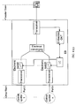
- FIG. 4 (a) , FIG. 4 (b) , FIG. 4 (c) , and FIG. 4 (d) are schematic structure diagrams of improved special EBs.
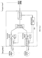
- the improved special EB includes: an optical switch, a tap, an optical splitter, an embedded ONT, a local controller (LC), and an optical amplifier (OA).
- the uplink needs to be separated from the downlink.
- FIG. 11 (a) For the specific EB structure, see FIG. 11 (a) .
- the tap is configured to split a small part of light from the optical channel and send it to the embedded ONT.
- the embedded ONT is configured to communicate with the OLTn+1 and control an optical switch.
- an ONT is embedded in the EB to serve as a control device, and other apparatuses with similar functions may also be used to control the optical switch.
- the choice of the specific apparatus does not constitute a limitation on the present invention.
- an independent LC may be introduced to separate the function of controlling the optical switch from the embedded ONT, and the embedded ONT is mainly configured to communicate with the OLTn+1.
- the normal state of the optical switch is disconnected.
- the optical switch corresponding to port m is connected.
- the optical switch may also be a mechanical switch or an electronic switch.
- the OA is configured to amplify received optical signals.
- the OLTn+1 may adjust the corresponding OA power amplification coefficient of the EBn+1 through the embedded ONT, or the EBn+1 needs to adaptively adjust the corresponding OA power amplification coefficient, so that the protection optical link after the switchover may take over the working OLT perfectly.
- the optical splitter is configured to converge multiple optical signals into one optical signal, or split one optical signal into multiple optical signals.
- the optical splitter may be used.
- a wavelength division multiplexing (WDM) device is used to replace the optical splitter.
- An optical-electrical-optical (OEO) transceiver may be used to replace the OA or the OA is directly used. If the ONU and OLT use different wavelengths, wavelength conversion needs to be performed in the EB. Usually, the uplink needs to be separated from the downlink. For the specific EB structure, refer to FIG 11 (a) FIG11 (b) .
- the OEO transceiver is configured to: convert received optical signals into electrical signals, process the electrical signals, convert the processed electrical signals into new optical signals, and forward the new optical signals.
- the OLTn+1 adjusts the corresponding OEO power amplification efficient of the EBn+1 through the embedded ONT, or the EBn+1 needs to adaptively adjust the corresponding OEO power amplification efficient, so that the protection optical link after the switchover may take over the working OLT perfectly.
- FIG. 4 (c) differs from FIG. 4 (a) and FIG. 4 (b) in that: optical signals are converted into electrical signals first, and then the electrical signals are converged/diverged and finally converted into optical signals.
- a circuit switch such as a switch metal oxide semiconductor (MOS) and a switch transistor
- MOS switch metal oxide semiconductor
- switch transistor may be used to enable or disable the protection link, so that the system may easily control the connection or disconnection of the link.
- the improved EB includes: an electrical converging module, an electronic switch, an embedded ONT, a local controller (LC), and a transceiver.
- the uplink needs to be separated from the downlink.
- FIG. 11 (c) For the specific EB structure, refer to FIG. 11 (c) .
- the electrical converging module is configured to diverge and converge electrical signals and includes two types.
- the first type of electrical converging module is equivalent to an electrical splitter, and it diverges or splits downlink electrical signals, and converges or combines uplink electrical signals.
- the first type of electrical converging module is similar to a pure optical splitter in functions, and may be called a virtual splitter. Specifically, it splits a downlink physical signal of the PON into multiple identical downlink physical signals in the electrical domain rather than the optical domain, and superimposes and combines multiple uplink physical signals of the PON into one uplink physical signal.
- the second type of electrical converging module is equivalent to a multiplexer (MUX)/demultiplexer (DeMUX), and demultiplexes downlink electrical signals and multiplexes uplink electrical signals.
- MUX multiplexer
- DeMUX demultiplexer
- the EB needs to communicate with the OLTn+1 through the embedded ONT or the LC by using the routing control function of the MUX/DeMUX.
- the normal state of the electronic switch is disconnected.
- the electronic switch corresponding to port m is connected.
- the electronic switch may also be a mechanical switch.
- the electronic switch may be integrated with the transceiver, that is, the transceiver itself may have the switch function.
- the transceiver is configured to convert received optical signals into electrical signals or convert electrical signals into optical signals.
- the OLTn+1 adjusts the transmit power of the corresponding transceiver of the EBn+1 through the embedded ONT, or the EBn+1 needs to adaptively adjust the transmission power of the corresponding transceiver, so that the protection optical link after the switchover may take over the working OLT perfectly.
- Transceivers of different ports may use different PON modes, for example, a port 1 uses the GPON or EPON mode, and a port 2 uses the next generation GPON or EPON mode.
- the switch for triggering the switchover is controlled by the embedded ONT. It is appreciated that the switch may also be controlled by the transceiver.
- the switchover control device may be set independently or integrated into devices such as an optical detector, a transceiver, and an embedded ONT. For example, an independent LC may be introduced to separate the function of controlling the switch from the embedded ONT, and the embedded ONT is mainly configured to communicate with OLTn+1.
- FIG. 4 (d) differs from FIG. 4 (a) and FIG. 4 (b) in that: the optical switch is replaced with an OA or OEO transceiver at each ONU port, that is, the OA or OEO transceiver implements not only the OA or OEO function but also implements the switch function. Enabling or disabling of the OA or OEO transceiver is controlled by the embedded ONT. Other apparatuses with similar functions may also be used to control the optical switch. The choice of the specific apparatus does not constitute a limitation on the present invention.
- an independent LC may be introduced to separate the function of controlling the enabling or disabling of the OA or OEO transceiver from the embedded ONT, and the embedded ONT is mainly configured to communicate with OLTn+1. If the ONU and OLT use different wavelengths, wavelength conversion needs to be performed in the EB.
- OEO transceivers of different ports may use different PON modes, for example, a port 1 uses the GPON or EPON mode, and a port 2 uses the next generation GPON or EPON mode.
- the uplink needs to be separated from the downlink.
- FIG. 11 (d) FIG. 11 (e) For the specific EB structure, refer to FIG. 11 (d) FIG. 11 (e) .
- L2CP is also called an Access Node Control Protocol (ANCP).
- ANCP Access Node Control Protocol
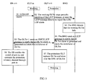
- FIG. 5 is a flowchart of triggering a switchover through a management system or an IP edge node (such as a BNG/BRAS).
- a management system or an IP edge node (such as a BNG/BRAS).
- the optical switch of port m of the EB when the working OLTm works normally, the optical switch of port m of the EB is disabled.
- the working OLTm reports an L2CP message or a keep-alive message to the BNG periodically, indicating the working OLTm or mth feeder fiber is normal.
- the process includes the following steps:
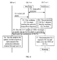
- FIG. 6 is a flowchart of triggering a switchover by the OLT.
- the optical switch of port m of the EB is disabled. The specific process includes the following steps:
- the following describes how the L2CP, OMCI, or Ethernet OAM protocol is applied to perform a switchover according to the first embodiment, and the flowchart is shown in FIG. 7 .
- the optical switch of port m of the EB is disabled.
- the specific process includes the following steps:
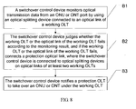
- a PON protection method is provided. As shown in FIG. 8 , the method includes the following steps:
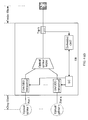
- FIG. 9 (a) , FIG. 9 (b) , FIG. 9 (c) , and FIG. 9 (d) are schematic structure diagrams of improved special EBs.
- the EB in FIG. 9 (a) includes: an OD, an optical switch, a tap, an optical splitter, an embedded ONT, an LC, and an OA or OEO transceiver.
- the OD is equivalent to an OLT receiver, and is configured to detect uplink optical signals and parse uplink optical transmission data.
- the specific function is: monitoring uplink optical transmission data from the ONU port; if no uplink transmission data is monitored within a certain time, reporting to the OLT through the embedded ONT that the feeder fiber or working OLT at the corresponding port m may fail, and triggering to enable the optical switch directly or through the LC so as to connect the communication channel of the corresponding port.
- the optical splitter may be used.
- a WDM device is used to replace the optical splitter.
- An OEO transceiver may be used to replace the OA or the OA is directly used. If the ONU and OLT use different wavelengths, wavelength conversion needs to be performed in the EB. Usually, the uplink needs to be separated from the downlink. For the specific EB structure, refer to FIG. 11 (a) FIG. 11 (b) .
- optical switch tap, optical splitter, embedded ONT, LC, OA or OEO transceiver, WDM device, and OEO transceiver, refer to descriptions in the first embodiment.
- the improved EB includes: an electrical converging module, an electronic switch, an embedded ONT, an LC, and a transceiver.
- the uplink needs to be separated from the downlink.
- FIG 11 (c) For the specific EB structure, refer to FIG 11 (c) .
- Transceivers of different ports may use different PON modes, for example, a port 1 uses the GPON or EPON mode, and a port 2 uses the next generation GPON or EPON mode.
- the transceiver needs to monitor the data, which is transmitted on the working optical link, through interfaces, and according to the monitoring result, control the disabling or enabling of the switch directly or through the LC to implement a switchover.
- the embedded ONT may also control the disabling or enabling of the switch according to the monitoring result of the transceiver; in this case, the transceiver needs to feed back the monitoring result to the embedded ONT.
- FIG. 9 (d) differs from FIG. 9 (a) in that: the optical switch is replaced with an OA at each ONU port, that is, the OA implements both the OA function and the switch function. Enabling or disabling of the OA is controlled by the embedded ONT. Other apparatuses with similar functions may also be used to control the optical switch. The choice of the specific apparatus does not constitute a limitation on the present invention. For example, an independent LC may be introduced to separate the function of controlling the enabling or disabling of the OA from the embedded ONT, and the embedded ONT is mainly configured to communicate with the OLTn+1.
- OEO transceivers of different ports may use different PON modes, for example, a port 1 uses the GPON or EPON mode, and a port 2 uses the next generation GPON or EPON mode. If the ONU and OLT use different wavelengths, wavelength conversion needs to be performed in the EB. Usually, the uplink needs to be separated from the downlink. For the specific EB structure, refer to FIG 11 (d) .
- a PON protection method is provided.
- the method in this embodiment differs from the method in the second embodiment in that:
- the switchover control device judges whether the detector monitors the uplink transmission data of the ONU or ONT within a preset time; if the detector monitors the uplink transmission data of the ONU or ONT within a preset time, the switchover control device continues the step of switching over the protection OLT to the working OLT to make the protection OLT take over the ONU or ONT under the working OLT. If the detector monitors no uplink transmission data of the ONU or ONT within a preset time, the protection OLT disables the laser, and gives up the communication connection with the ONU or ONT.
- the method further includes the following steps: judge whether abnormally emitted light occupies the uplink channel, and if abnormally emitted light occupies the uplink channel, turn off (disable) the uplink switch of the ONU or ONT.
- the process of judging whether abnormally emitted light occupies the uplink channel may use the following mode:
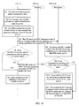
- the process includes the following steps:
- an embodiment of the present invention provides an improved EB supporting PON protection.
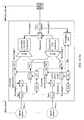
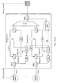
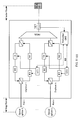
- the functional block diagrams of the EB are shown in FIG. 11 (a) , FIG. 11 (b) , FIG. 11 (c) , FIG. 11 (d) , and FIG. 11 (e) .
- the uplink is separated from the downlink, and an OD, a downlink optical switch, and a uplink optical switch are introduced.
- the whole EB includes a tap, an optical splitter/WDM device, an uplink optical switch, a downlink optical switch, an OD, an embedded ONT, an uplink OA or OEO transceiver, a downlink OA or OEO transceiver, an LC, and a duplexer. If the ONU and OLT use different wavelengths, wavelength conversion (WC) needs to be performed in the EB.
- the WC module is introduced in the uplink and downlink paths.
- the duplexer is configured to implement single-fiber bidirectional transceiving, namely, combine the uplink and downlink into one.
- the normal state of the uplink and downlink optical switches is disconnected.
- the uplink optical switch and downlink optical switch corresponding to port m are connected.
- the OD is equivalent to an OLT receiver and is configured to detect uplink optical signals and parse uplink optical transmission data.
- the OD has the following functions:
- the switchover process based on the EB in FIG. 11 is similar to the switchover process based on the EBs in FIG. 4 and FIG. 9 , and the only difference is that: in the switchover process based on the EB in FIG. 9 , the uplink and downlink optical switches of port m are enabled or disabled simultaneously.
- the ODm of the EB identifies and detects whether ONUs under port m include the ONU that emits light abnormally.
- the detection process is as follows:
- the EB extracts a small part of light from each port m through tap m and detects the light through the ODm; when the ODm determines that the abnormally emitted light of the ONU under port m occupies the uplink channel, the ODm triggers to disable the uplink optical switch directly or through the LCm, and then reports the faulty port m to the OLT through the embedded ONT.
- the uplink channel of the faulty port m is isolated in time, so as to ensure that the uplink channels of other ports are not affected and keeps the downlink channel of the faulty port m (because the downlink optical switch is still enabled) smooth. Then the OLTn+1 may command all ONUs under the faulty port m to stop sending uplink optical signals, and record the value of the total optical power at this time.
- FIG. 11 (c) differs from FIG 11 (b) in that: optical signals are first converted into electrical signals, and after processed by the electrical converging unit, the signals are converted into optical signals and sent out, where:
- the TX/RX of different ports may use different PON modes, for example, a port 1 uses the GPON or EPON mode, and a port 2 uses the next generation GPON or EPON mode.
- FIG. 11 (d) and FIG. 11 (e) differ from FIG. 11 (a) and FIG. 4 (b) in that: the switch is replaced with an OA/TX/RX at each ONU port, that is, the OA/TX/RX implements both the OA/TX/RX function and the switch function. Enabling or disabling of the OA/TX/RX is controlled by the embedded ONT. Other apparatuses with similar functions may also be used to control the switch. The choice of the specific apparatus does not constitute a limitation on the present invention.
- an independent LC may be introduced to separate the function of controlling the enabling or disabling of the OA/TX/RX from the embedded ONT, and the embedded ONT is mainly configured to communicate with the OLTn+1.
- the TX/RX of different ports may use different PON modes, for example, a port 1 uses the GPON or EPON mode, and a port 2 uses the next generation GPON or EPON mode. If the ONU and OLT use different wavelengths, wavelength conversion (WC) needs to be performed in the EB.
- the wavelength conversion module is introduced in the uplink and downlink paths.
- the program may be stored in a computer readable storage medium, which can be a magnetic disk, a compact disk-read only memory (CD-ROM), a read only memory (ROM), or a random access memory (RAM).
- a computer readable storage medium can be a magnetic disk, a compact disk-read only memory (CD-ROM), a read only memory (ROM), or a random access memory (RAM).
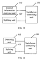
- a switchover control device is provided. As shown in FIG 12 , the device includes:
- the splitting unit is specifically configured to control the link between the splitting unit and the optical splitting device on the optical link of the working OLT by enabling the switch between the splitting unit and the optical splitting device on the optical link of the working OLT.
- the splitting unit may be an optical splitter, an EB, a WDM device, or an electrical converging module.
- the electrical converging module is specifically configured to: split downlink electrical signals and combine uplink electrical signals, or demultiplex downlink electrical signals and multiplex uplink electrical signals;
- the WDM device is specifically configured to perform wavelength conversion when the ONU and OLT use different wavelengths.
- a switchover controlling unit 330 configured to connect a protection optical link according to the information about the working OLT or optical link information of the working OLT after the control information receiving unit receives a switchover request, and instruct the protection OLT to take over the ONU or ONT under the working OLT;
- the switchover control device may further include a power adjusting unit, which is configured to adjust a power amplification coefficient of the protection optical link and adjust transceiving signal power of the protection OLT.
- a switchover control device is provided. As shown in FIG. 13 , the device includes:
- the detecting unit in this embodiment is an OD or a transceiver; the switchover control device may further include a power adjusting unit which is configured to adjust a power amplification coefficient of the protection optical link and adjust transceiving signal power of the protection OLT.
- the switchover controlling units in the third and fourth embodiments are configured to perform judgment and control inside the switchover control device, and may be integrated in existing entity hardware, for example, in the embedded OLT, OA, OEO transceiver, OD, LC, or transceiver.
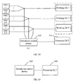
- a PON protection system is provided. As shown in FIG. 14 , the system includes: a protection OLT 510, a switchover control device 520, a protection OLT 530, and a working OLT1 to a working OLTn (where n is an integer greater than 1) and corresponding optical links, where the protection OLT communicates with the switchover control device through L2CP/OMCI/Etherent OAM messages.
- the switchover control device 520 connected to the optical links of the OLT1 to OLTn, is configured to receive a switchover request and connect, according to the information about a working OLT or the optical link information of the working OLT, the protection optical link, where the switchover request may be sent by the protection OLT 520 or IP edge node or the ONU or EB under the working OLT and may carry the information about the working OLT or optical link information of the working OLT.
- the protection OLT 510 is configured to send the switchover request to the switchover control device and take over an ONU or ONT under the working OLT after the protection optical link is connected.
- a PON protection system is provided. As shown in FIG. 15 , the system includes a switchover control device 620 and a protection OLT 620, where the protection OLT communicates with the switchover control device through L2CP/OMCI/Ethernet OAM messages.
- the switchover control device 610 connected to optical splitting devices on optical links of at least two working OLTs, is configured to: monitor optical transmission data from an ONU or ONT port by using an optical splitting device connected to an optical link of a working OLT, judge whether the working OLT or the optical link of the working OLT fails according to the monitoring result, and if the working OLT or the optical link of the working OLT fails, connect a protection optical link; and
- the protection OLT 620 is configured to take over an ONU or ONT under the working OLT through the protection optical link after the switchover control device 610 connects the protection optical link.
- the protection OLT, the switchover control device, and the working OLT may communicate with each other through L2CP or OMCI messages.
Landscapes
- Engineering & Computer Science (AREA)
- Computer Networks & Wireless Communication (AREA)
- Signal Processing (AREA)
- Environmental & Geological Engineering (AREA)
- Optical Communication System (AREA)
- Small-Scale Networks (AREA)
Claims (9)
- Procédé de protection d'un réseau optique passif, PON (Passive Optical Network), comprenant :la réception (A1), par un dispositif de commande de basculement connecté à des liaisons optiques d'au moins deux terminaux de ligne optique fonctionnels, OLT (Optical Line Terminal), et connecté en outre à un OLT de protection par l'intermédiaire d'une liaison optique de protection, d'une demande de basculement, la demande de basculement acheminant des informations concernant un OLT fonctionnel ou des informations de liaison optique de l'OLT fonctionnel ;la connexion (A2) de la liaison optique de protection conformément aux informations concernant l'OLT fonctionnel ou aux informations de liaison optique de l'OLT fonctionnel ; etl'envoi (A3) à l'OLT de protection d'une instruction lui ordonnant de prendre la relève d'une unité de réseau optique, ONU (Optical Network Unit), ou d'un terminal de réseau optique, ONT (Optical Network Terminal), situé en dessous de l'OLT fonctionnel,le procédé étant caractérisé en ce que :avant que le dispositif de commande de basculement reçoive la demande de basculement, le procédé comprend en outre :lorsque l'OLT de protection apprend que l'OLT fonctionnel ou que la liaison optique de l'OLT fonctionnel est défectueux, l'envoi par l'OLT de protection de la demande de basculement au dispositif de commande de basculement.
- Procédé selon la revendication 1, dans lequel l'ONU ou l'ONT se trouvant en dessous de l'OLT fonctionnel comprend :toutes les ONU ou tous les ONT se trouvant en dessous de l'OLT fonctionnel, ou une ONU ou un ONT correspondant à un port défectueux situé en dessous de l'OLT fonctionnel ; la connexion d'une liaison optique de protection en conformité avec les informations concernant l'OLT fonctionnel ou avec les informations de liaison optique de l'OLT fonctionnel comprend :l'activation d'une interface de communication avec un dispositif de séparation optique correspondant en conformité avec les informations concernant l'OLT fonctionnel ou avec les informations de liaison optique de l'OLT fonctionnel pour connecter une liaison optique entre l'ONU située en dessous de l'OLT fonctionnel et l'OLT de protection, le dispositif de commande de basculement étant connecté à des dispositifs de séparation optique sur les liaisons optiques des au moins deux OLT fonctionnels.
- Procédé selon la revendication 1 ou 2, dans lequel le processus d'apprentissage par l'OLT de protection du fait que l'OLT fonctionnel ou la liaison optique de l'OLT fonctionnel est défectueux, comprend :la réception, par l'OLT de protection, d'un message envoyé par un noeud de bord à Protocole Internet, IP, le message acheminant les informations concernant l'OLT fonctionnel défectueux ou les informations de liaison optique de l'OLT fonctionnel défectueux ;ou l'interaction, entre l'OLT de protection et l'OLT fonctionnel, pour apprendre que l'OLT fonctionnel ou la liaison optique de l'OLT fonctionnel est défectueux.
- Procédé selon l'une quelconque des revendications 1-3, comprenant en outre, avant que l'OLT de protection prenne la relève de l'ONU ou de l'ONT situé en dessous de l'OLT fonctionnel :l'envoi, par le dispositif de commande de basculement à l'OLT de protection, d'une instruction ordonnant à ce dernier de prendre la relève de l'ONU ou de l'ONT situé en dessous de l'OLT fonctionnel.
- Procédé de protection d'un réseau optique passif, PON (Passive Optical Network), comprenant :la surveillance (Q1), par un dispositif de commande de basculement, de données de transmission optique provenant de ports d'une unité de réseau optique, ONU, ou d'un terminal de réseau optique, ONT, en utilisant un dispositif de séparation optique connecté à une liaison optique d'un terminal de ligne optique fonctionnel, OLT ;le fait de déterminer si l'OLT fonctionnel ou la ligne optique de l'OLT fonctionnel est défectueux en fonction d'un résultat de surveillance et, si l'OLT fonctionnel ou la liaison optique de l'OLT fonctionnel est défectueux, connecter une liaison optique de protection, le dispositif de commande de basculement étant connecté à des dispositifs de séparation optique sur des liaisons optiques d'au moins deux OLT fonctionnels etétant en outre connecté à un OLT de protection par l'intermédiaire de la liaison optique de protection ; etl'envoi (Q4) à l'OLT de protection d'une instruction lui ordonnant de prendre la relève d'une ONU ou d'un ONT situé en dessous de l'OLT fonctionnel ;le procédé étant caractérisé en ce que :le dispositif de commande de basculement est spécifiquement connecté au dispositif de séparation optique sur la liaison optique de l'OLT fonctionnel par l'intermédiaire d'un détecteur optique, OD (OD1, ODn) (Optical Detector), ou d'un émetteur-récepteur ; et en ce quela surveillance, par le dispositif de commande de basculement, des données de transmission optique provenant du port de l'ONU ou de l'ONT en utilisant le dispositif de séparation optique connecté à la liaison optique de l'OLT fonctionnel comprend :la surveillance (Q1) par l'OD ou l'émetteur-récepteur, de données de transmission optique de liaison montante provenant du port de l'ONU ou de l'ONT en utilisant le dispositif de séparation optique connecté à la liaison optique de l'OLT fonctionnel ;dans lequel, après l'envoi (Q4) à l'OLT de protection d'une instruction lui ordonnant de prendre la relève de l'ONU ou de l'ONT situé en dessous de l'OLT fonctionnel, le procédé comprend en outre :l'activation, par l'OLT de protection, d'un laser et l'établissement d'une connexion de communication avec l'ONU ou l'ONT situé en dessous de l'OLT (Q5) ;la détermination (Q6), par le dispositif de commande de basculement, du fait de savoir si l'OD surveille des données de transmission de liaison montante de l'ONU ou de l'ONT avant un temps prédéfini ; etsi les données de transmission de liaison montante de l'ONU ou de l'ONT sont surveillées, le fait que l'OLT de protection continue de prendre la relève de l'ONU oude l'ONT situé en dessous de l'OLT fonctionnel (Q7) ;si les données de transmission de liaison montante de l'ONU ou de l'ONT ne sont pas surveillées, la désactivation, par l'OLT de protection, du laser (Q9), et l'abandon (Q10) d'une connexion de communication avec l'ONU ou l'ONT.
- Procédé selon la revendication 5, dans lequel le processus de détermination du fait de savoir si l'OLT fonctionnel ou la liaison optique de l'OLT fonctionnel est défectueux conformément au résultat de la surveillance comprend :si le dispositif de commande de basculement ne surveille pas les données de transmission de liaison montante avant un temps prédéfini, la détermination, par le dispositif de commande de basculement, du fait de savoir si l'OLT fonctionnel ou la liaison optique de l'OLT fonctionnel est défectueux.
- Procédé selon la revendication 6, dans lequel, après que l'OLT de protection a basculé sur l'OLT fonctionnel et a pris la relève de l'ONU ou de l'ONT situé en dessous de l'OLT fonctionnel, le procédé comprend en outre : la détermination du fait de savoir si une lumière émise anormalement occupe un canal de liaison montante et si la lumière émise anormalement occupe un canal de liaison montante, la déconnexion d'un canal de liaison montante de l'ONU ou de l'ONT correspondant à la lumière émise anormalement.
- Système de protection de réseau optique passif, PON, comprenant un terminal de ligne optique, OLT, de protection, et un dispositif de commande de basculement, dans lequel :le dispositif de commande de basculement est connecté à des liaisons optiques d'au moins deux terminaux de ligne optique OLT fonctionnels, et est en outre connecté à l'OLT de protection par l'intermédiaire d'une liaison optique de protection, et est configuré pour recevoir une demande de basculement, la demande de basculement acheminant des informations concernant un OLT fonctionnel ou des informations de liaison optique de l'OLT fonctionnel ; pour connecter la liaison optique de protection en conformité avec les informations concernant l'OLT fonctionnel ou avec les informations de liaison optique de l'OLT fonctionnel ;l'OLT de protection est configuré pour prendre la relève de l'ONU ou de l'ONT situé en dessous de l'OLT fonctionnel en utilisant la liaison optique de protection après que le dispositif de commande de basculement a connecté la liaison optique de protection,le système étant caractérisé en ce que :l'OLT de protection est en outre configuré pour apprendre que l'OLT fonctionnel ou que la liaison optique de l'OLT fonctionnel est défectueux, et pour envoyer la demande de basculement au dispositif de commande de basculement.
- Système de protection de réseau optique passif, PON, comprenant un terminal de ligne optique, OLT, de protection, et un dispositif de commande de basculement, dans lequel :le dispositif de commande de basculement est connecté à des dispositifs de séparation optique sur des liaisons optiques d'au moins deux OLT fonctionnels et est en outre connecté à un OLT de protection par l'intermédiaire de la liaison optique de protection, et est configuré pour surveiller des données de transmission optique provenant de ports d'une unité de réseau optique, ONU, ou d'un terminal de réseau optique, ONT, en utilisant un dispositif de séparation optique connecté à une liaison optique d'un OLT fonctionnel, pour déterminer si l'OLT fonctionnel ou la liaison optique de l'OLT fonctionnel est défectueux en conformité avec un résultat de surveillance, et si l'OLT fonctionnel ou la liaison optique de l'OLT fonctionnel est défectueux, pour connecter une liaison optique de protection ; et pour envoyer à l'OLT de protection une instruction lui ordonnant de prendre la relève d'une ONU ou d'un ONT situé en dessous de l'OLT ;le système étant caractérisé en ce que :le dispositif de commande de basculement est connecté au dispositif de séparation optique sur la liaison optique de l'OLT fonctionnel par l'intermédiaire d'un détecteur optique, OD, ou d'un émetteur-récepteur ; et l'OD ou l'émetteur-récepteur est configuré pour surveiller des données de transmission optique de liaison montante provenant du port de l'ONU ou de l'ONT en utilisant le dispositif de séparation optique connecté à la liaison optique de l'OLT fonctionnel ;l'OLT de protection est configuré pour activer un laser et établir une connexion de communication avec l'ONU ou l'ONT situé en dessous de l'OLT ;le dispositif de commande de basculement est en outre configuré pour déterminer si l'OD surveille des données de transmission de liaison montante de l'ONU ou de l'ONT avant un temps prédéfini ;l'OLT de protection est en outre configuré pour continuer de prendre la relève de l'ONU ou de l'ONT situé en dessous de l'OLT si les données de transmission de liaison montante de l'ONU ou de l'ONT sont surveillées, ou pour désactiver le laser et abandonner une connexion de communication avec l'ONU ou l'ONT si les données de transmission de liaison montante de l'ONU ou de l'ONT ne sont pas surveillées.
Applications Claiming Priority (3)
| Application Number | Priority Date | Filing Date | Title |
|---|---|---|---|
| CN200910133114 | 2009-04-02 | ||
| CN200910149578.2A CN101854566B (zh) | 2009-04-02 | 2009-06-29 | 无源光网络保护方法、主备切换控制设备和系统 |
| PCT/CN2010/071304 WO2010111923A1 (fr) | 2009-04-02 | 2010-03-25 | Procede de protection de reseau optique passif, dispositif et systeme de commande de commutateur de mise en attente maitre |
Publications (3)
| Publication Number | Publication Date |
|---|---|
| EP2393237A4 EP2393237A4 (fr) | 2011-12-07 |
| EP2393237A1 EP2393237A1 (fr) | 2011-12-07 |
| EP2393237B1 true EP2393237B1 (fr) | 2012-10-03 |
Family
ID=42827487
Family Applications (1)
| Application Number | Title | Priority Date | Filing Date |
|---|---|---|---|
| EP20100758025 Not-in-force EP2393237B1 (fr) | 2009-04-02 | 2010-03-25 | Procede de protection de reseau optique passif, dispositif et systeme de commande de commutateur de mise en attente maitre |
Country Status (4)
| Country | Link |
|---|---|
| US (1) | US8428456B2 (fr) |
| EP (1) | EP2393237B1 (fr) |
| CN (1) | CN101854566B (fr) |
| WO (1) | WO2010111923A1 (fr) |
Families Citing this family (59)
| Publication number | Priority date | Publication date | Assignee | Title |
|---|---|---|---|---|
| CN101453666B (zh) * | 2007-12-07 | 2012-07-04 | 华为技术有限公司 | 无源光网络的主备链路保护方法、环路系统及装置 |
| WO2009116904A1 (fr) * | 2008-03-17 | 2009-09-24 | Telefonaktiebolaget L M Ericsson (Publ) | Technique de protection immédiate pour réseau optique passif |
| AU2008353014B2 (en) * | 2008-03-17 | 2013-09-12 | Telefonaktiebolaget L M Ericsson (Publ) | Fast protection scheme for passive optical network |
| CN101964924B (zh) * | 2009-07-24 | 2013-11-06 | 华为技术有限公司 | 无源光网络中传输信息的方法、装置和系统 |
| US8346095B2 (en) | 2009-12-07 | 2013-01-01 | Centurylink Intellectual Property Llc | System and method for providing multi-provider telecommunications services over a passive optical network |
| US8699326B2 (en) * | 2011-01-31 | 2014-04-15 | Telefonaktiebolaget L M Ericsson (Publ) | Optical network automatic protection switching |
| US20120251097A1 (en) * | 2011-03-28 | 2012-10-04 | Tellabs Operations, Inc. | Passive architectural optical distribution network |
| JP5699760B2 (ja) * | 2011-04-04 | 2015-04-15 | 富士通株式会社 | 光増幅装置、光増幅装置の制御方法、光受信局及び光伝送システム |
| US20120288273A1 (en) * | 2011-05-12 | 2012-11-15 | Alcatel-Lucent Usa, Inc. | Intelligent splitter monitor |
| US20130183035A1 (en) * | 2011-12-01 | 2013-07-18 | Joseph L. Smith | Enhanced PON And Splitter Module And Associated Method |
| CN103378918B (zh) * | 2012-04-19 | 2019-08-06 | 中兴通讯股份有限公司 | 通道调整方法及装置 |
| CN103686470B (zh) * | 2012-09-24 | 2017-07-18 | 上海贝尔股份有限公司 | 光信号分配装置 |
| US8953936B2 (en) * | 2012-10-01 | 2015-02-10 | Telefonaktiebolaget L M Ericsson (Publ) | Method for protection of multi-wavelength passive optical network |
| EP2775733A1 (fr) * | 2013-03-05 | 2014-09-10 | British Telecommunications public limited company | Réseau de communications |
| US9179203B2 (en) * | 2013-09-30 | 2015-11-03 | Verizon Patent And Licensing Inc. | Optical network system architecture |
| CN103580926B (zh) * | 2013-11-13 | 2017-12-05 | 国家电网公司 | 一种轻量热备系统同步方法 |
| CN103701519B (zh) * | 2013-12-18 | 2016-05-04 | 烽火通信科技股份有限公司 | 无源光网络的主备用判决方法 |
| ES2710703T3 (es) * | 2014-01-23 | 2019-04-26 | Huawei Tech Co Ltd | Método de comunicación de terminal de línea óptica y dispositivo con estructura de datos |
| CN104869479B (zh) * | 2014-02-26 | 2019-03-01 | 上海诺基亚贝尔股份有限公司 | 一种无源光网络架构 |
| US9942413B2 (en) | 2014-04-02 | 2018-04-10 | Centurylink Intellectual Property Llc | Multi-network access gateway |
| US9634761B2 (en) * | 2014-04-11 | 2017-04-25 | Alcatel Lucent | Apparatus and method for optical-network monitoring |
| WO2016027820A1 (fr) * | 2014-08-22 | 2016-02-25 | 日本電信電話株式会社 | Dispositif côté station dans un système de transmission optique, système de transmission optique et procédé de transmission optique |
| CN105634774A (zh) * | 2014-10-31 | 2016-06-01 | 中兴通讯股份有限公司 | 恢复链路通讯的方法、业务线卡及系统 |
| CN105790832B (zh) * | 2014-12-24 | 2018-12-14 | 中国电信股份有限公司 | 异常发光光网络单元onu的检测诊断方法和装置 |
| CN104954065B (zh) * | 2015-05-22 | 2018-02-13 | 上海斐讯数据通信技术有限公司 | 一种无源光网络系统及通信方法 |
| US10148348B2 (en) * | 2015-07-17 | 2018-12-04 | Corning Optical Communications LLC | Optical-electrical interface devices and systems with optical communication pathway redundancy |
| WO2017016592A1 (fr) * | 2015-07-27 | 2017-02-02 | Telefonaktiebolaget Lm Ericsson (Publ) | Appareil de protection d'une liaison optique |
| US10122544B2 (en) * | 2015-08-19 | 2018-11-06 | Arris Enterprises Llc | N+0 redundancy in a network access system |
| US10523356B2 (en) * | 2016-05-31 | 2019-12-31 | Cable Television Laborties, Inc. | System and methods for coherent optical extension |
| CN107819509A (zh) * | 2016-09-12 | 2018-03-20 | 恒为科技(上海)股份有限公司 | 一种光链路保护的系统 |
| CN106850052A (zh) * | 2017-01-06 | 2017-06-13 | 东华大学 | 一种应用于ip广播技术的基于i‑tmux的主/备光路热备份系统 |
| CN110022174A (zh) * | 2018-01-08 | 2019-07-16 | 中兴通讯股份有限公司 | 光网络单元业务保护的方法及装置 |
| US10997041B2 (en) | 2018-04-25 | 2021-05-04 | Hewlett Packard Enterprise Development Lp | Method to disable or reboot unresponsive device with active uplink in a ring network |
| CN108833135B (zh) * | 2018-05-04 | 2023-06-06 | 深圳市共进电子股份有限公司 | 一种Mesh组网管理方法、管理设备以及延长器 |
| CN110769331B (zh) * | 2018-07-27 | 2022-03-29 | 中兴通讯股份有限公司 | 一种线卡及设计方法、通信控制方法、装置、存储介质 |
| CN111385678B (zh) * | 2018-12-29 | 2023-05-12 | 中兴通讯股份有限公司 | 一种实现光链路通道自协商的方法和装置 |
| CN109889335B (zh) * | 2019-02-22 | 2021-07-09 | 中国电子科技集团公司第三十研究所 | 基于随机分流加密传输的新型高安全光链路保密通信方法 |
| CN110166858B (zh) * | 2019-05-30 | 2021-12-07 | 深圳市友华软件科技有限公司 | Pon网络的onu自适应切换方法 |
| CN110212979B (zh) * | 2019-07-09 | 2020-09-11 | 国网浙江省电力有限公司信息通信分公司 | 一种光传输网络故障定位方法 |
| CN110446125B (zh) * | 2019-08-27 | 2024-05-24 | 成都华跃科技有限公司 | 光网络系统、光路切换方法、光切换指令下发方法及光分路设备 |
| CN110601749B (zh) * | 2019-11-04 | 2024-07-30 | 国网新疆电力有限公司信息通信公司 | 一种光纤通信控制系统 |
| CN112787917A (zh) * | 2019-11-11 | 2021-05-11 | 中兴通讯股份有限公司 | 灵活以太网的保护方法、端节点、保护组网和存储介质 |
| CN110990307A (zh) * | 2019-11-29 | 2020-04-10 | 浪潮商用机器有限公司 | 一种服务器的布线系统以及服务器 |
| US12063072B2 (en) * | 2020-03-06 | 2024-08-13 | Nippon Telegraph And Telephone Corporation | Communication system and OLT system |
| CN113395114B (zh) * | 2020-03-12 | 2022-09-16 | 华为技术有限公司 | 光模块、数据中心系统以及数据传输方法 |
| CN111464236B (zh) * | 2020-05-29 | 2024-09-24 | 中山市美速光电技术有限公司 | 一种光线路保护设备、系统及网络终端管理平台 |
| TWI730836B (zh) * | 2020-07-06 | 2021-06-11 | 瑞昱半導體股份有限公司 | 光纖網路方法和相關裝置 |
| CN113938214A (zh) * | 2020-07-13 | 2022-01-14 | 瑞昱半导体股份有限公司 | 光纤网络方法和相关装置 |
| US12273185B2 (en) | 2020-07-17 | 2025-04-08 | Telefonaktiebolaget Lm Ericsson (Publ) | Optical transport network protection architecture, nodes and method |
| CN114189768B (zh) * | 2020-09-14 | 2025-12-30 | 中兴通讯股份有限公司 | 无源光纤网络的业务管理方法、装置、光线路终端及介质 |
| CN114765471A (zh) * | 2021-01-14 | 2022-07-19 | 华为技术有限公司 | 一种分光装置、双模onu、光网络系统及通信方法 |
| CN115378754B (zh) * | 2021-05-21 | 2025-01-21 | 深圳引望智能技术有限公司 | Can通信冗余的方法和通信装置 |
| CN113472431B (zh) * | 2021-06-25 | 2022-05-13 | 中航光电科技股份有限公司 | 一种具有双主架构的新型链式光通信网络 |
| CN116961739A (zh) * | 2022-04-14 | 2023-10-27 | 华为技术有限公司 | 一种光传输设备、业务设备、业务传输的方法和系统 |
| CN116016133A (zh) * | 2022-12-13 | 2023-04-25 | 中国建设银行股份有限公司江苏省分行 | 一种设备切换方法及装置、存储介质及电子设备 |
| CN118842511A (zh) * | 2023-04-24 | 2024-10-25 | 中国电信股份有限公司 | 光线路信道终端保护方法、装置、设备及存储介质 |
| CN118075643A (zh) * | 2023-07-24 | 2024-05-24 | 锐捷网络股份有限公司 | 一种链路切换方法、装置及电子设备 |
| CN118138926B (zh) * | 2024-05-10 | 2024-07-02 | 国网浙江省电力有限公司信息通信分公司 | 一种电力光传送网的接入层系统 |
| CN119854108A (zh) * | 2024-12-30 | 2025-04-18 | 广州芯德通信科技股份有限公司 | 一种故障olt设备快速替换方法、系统及计算机存储介质 |
Family Cites Families (6)
| Publication number | Priority date | Publication date | Assignee | Title |
|---|---|---|---|---|
| JP3350926B2 (ja) * | 1999-03-30 | 2002-11-25 | 日本電気株式会社 | Ponのプロテクション切り換え方法および装置 |
| CN1599292B (zh) * | 2003-09-19 | 2010-04-28 | 中兴通讯股份有限公司 | 一种带线路保护的单板备份方法及装置 |
| CN1703008A (zh) * | 2005-06-29 | 2005-11-30 | 飞博创(成都)科技有限公司 | 无源光网络保护方法及系统 |
| JP4696759B2 (ja) * | 2005-07-29 | 2011-06-08 | Kddi株式会社 | 光終端システム |
| JP4704842B2 (ja) * | 2005-08-01 | 2011-06-22 | 株式会社日立製作所 | Wdm型ponシステム |
| US9319758B2 (en) * | 2008-10-21 | 2016-04-19 | Broadcom Corporation | Method and system for protection switching in ethernet passive optical networks |
-
2009
- 2009-06-29 CN CN200910149578.2A patent/CN101854566B/zh not_active Expired - Fee Related
-
2010
- 2010-03-25 EP EP20100758025 patent/EP2393237B1/fr not_active Not-in-force
- 2010-03-25 WO PCT/CN2010/071304 patent/WO2010111923A1/fr not_active Ceased
-
2011
- 2011-08-31 US US13/222,964 patent/US8428456B2/en not_active Expired - Fee Related
Also Published As
| Publication number | Publication date |
|---|---|
| EP2393237A4 (fr) | 2011-12-07 |
| CN101854566B (zh) | 2014-08-13 |
| CN101854566A (zh) | 2010-10-06 |
| US20110317995A1 (en) | 2011-12-29 |
| WO2010111923A1 (fr) | 2010-10-07 |
| US8428456B2 (en) | 2013-04-23 |
| EP2393237A1 (fr) | 2011-12-07 |
Similar Documents
| Publication | Publication Date | Title |
|---|---|---|
| EP2393237B1 (fr) | Procede de protection de reseau optique passif, dispositif et systeme de commande de commutateur de mise en attente maitre | |
| EP1841097B1 (fr) | Procédé et système d'entretien d'un réseau optique passif | |
| CN103378918B (zh) | 通道调整方法及装置 | |
| JP5276935B2 (ja) | 受動光網システムおよびその障害特定方法 | |
| US9438368B2 (en) | Wavelength negotiation method and apparatus of multi-wavelength passive optical network, and multi-wavelength passive optical network system | |
| EP1802007B1 (fr) | Procédé de maintenance d'une réseau optique passif, unité de réseau optique, et terminal de ligne optique | |
| US8538261B2 (en) | Immediate protection scheme for passive optical network | |
| CN102823270B (zh) | 用于光网络中的保护的方法和装置 | |
| US20190182569A1 (en) | Passive optical network communications method, apparatus and system | |
| JP5073826B2 (ja) | フェイルセーフ光スプリッタ及び受動光ネットワークにおいて障害を分離する方法 | |
| TW201334438A (zh) | 被動光學網路中提供保護的裝置及方法 | |
| WO2010023721A1 (fr) | Système pon et procédé de redondance | |
| US20150358076A1 (en) | Port-dualized optical line terminal and passive optical network system capable of measuring rssi of standby line in standby port, and method of determining stability of standby line using the same | |
| CN101651495A (zh) | 一种波分复用无源光网络主干光纤保护的方法及装置 | |
| US8229296B2 (en) | Method and apparatus for channel protection switching of optical network device | |
| CN102594444B (zh) | 一种实现全保护方式的方法及系统 | |
| US7660529B2 (en) | System and method for providing failure protection in optical networks | |
| JP5089748B2 (ja) | 加入者宅側光回線終端装置 | |
| CN108989913A (zh) | 传输光信号的方法和无源光网络传输系统 | |
| Kanungoe et al. | Author's Accepted Manuscript | |
| KR20180110344A (ko) | 예비회선을 제공하는 wdm 기반 pon 거리 확장 장치 |
Legal Events
| Date | Code | Title | Description |
|---|---|---|---|
| PUAI | Public reference made under article 153(3) epc to a published international application that has entered the european phase |
Free format text: ORIGINAL CODE: 0009012 |
|
| 17P | Request for examination filed |
Effective date: 20110830 |
|
| A4 | Supplementary search report drawn up and despatched |
Effective date: 20110929 |
|
| AK | Designated contracting states |
Kind code of ref document: A1 Designated state(s): AT BE BG CH CY CZ DE DK EE ES FI FR GB GR HR HU IE IS IT LI LT LU LV MC MK MT NL NO PL PT RO SE SI SK SM TR |
|
| GRAP | Despatch of communication of intention to grant a patent |
Free format text: ORIGINAL CODE: EPIDOSNIGR1 |
|
| RIC1 | Information provided on ipc code assigned before grant |
Ipc: H04L 12/24 20060101AFI20120419BHEP Ipc: H04L 12/26 20060101ALI20120419BHEP Ipc: H04J 14/02 20060101ALI20120419BHEP Ipc: H04Q 11/00 20060101ALI20120419BHEP |
|
| DAX | Request for extension of the european patent (deleted) | ||
| GRAS | Grant fee paid |
Free format text: ORIGINAL CODE: EPIDOSNIGR3 |
|
| GRAA | (expected) grant |
Free format text: ORIGINAL CODE: 0009210 |
|
| AK | Designated contracting states |
Kind code of ref document: B1 Designated state(s): AT BE BG CH CY CZ DE DK EE ES FI FR GB GR HR HU IE IS IT LI LT LU LV MC MK MT NL NO PL PT RO SE SI SK SM TR |
|
| REG | Reference to a national code |
Ref country code: GB Ref legal event code: FG4D |
|
| REG | Reference to a national code |
Ref country code: AT Ref legal event code: REF Ref document number: 578418 Country of ref document: AT Kind code of ref document: T Effective date: 20121015 Ref country code: CH Ref legal event code: EP |
|
| REG | Reference to a national code |
Ref country code: IE Ref legal event code: FG4D |
|
| REG | Reference to a national code |
Ref country code: DE Ref legal event code: R096 Ref document number: 602010003091 Country of ref document: DE Effective date: 20121129 |
|
| REG | Reference to a national code |
Ref country code: AT Ref legal event code: MK05 Ref document number: 578418 Country of ref document: AT Kind code of ref document: T Effective date: 20121003 |
|
| PG25 | Lapsed in a contracting state [announced via postgrant information from national office to epo] |
Ref country code: SI Free format text: LAPSE BECAUSE OF FAILURE TO SUBMIT A TRANSLATION OF THE DESCRIPTION OR TO PAY THE FEE WITHIN THE PRESCRIBED TIME-LIMIT Effective date: 20121003 |
|
| REG | Reference to a national code |
Ref country code: NL Ref legal event code: VDEP Effective date: 20121003 |
|
| REG | Reference to a national code |
Ref country code: LT Ref legal event code: MG4D |
|
| PG25 | Lapsed in a contracting state [announced via postgrant information from national office to epo] |
Ref country code: NL Free format text: LAPSE BECAUSE OF FAILURE TO SUBMIT A TRANSLATION OF THE DESCRIPTION OR TO PAY THE FEE WITHIN THE PRESCRIBED TIME-LIMIT Effective date: 20121003 Ref country code: IS Free format text: LAPSE BECAUSE OF FAILURE TO SUBMIT A TRANSLATION OF THE DESCRIPTION OR TO PAY THE FEE WITHIN THE PRESCRIBED TIME-LIMIT Effective date: 20130203 Ref country code: SE Free format text: LAPSE BECAUSE OF FAILURE TO SUBMIT A TRANSLATION OF THE DESCRIPTION OR TO PAY THE FEE WITHIN THE PRESCRIBED TIME-LIMIT Effective date: 20121003 Ref country code: LT Free format text: LAPSE BECAUSE OF FAILURE TO SUBMIT A TRANSLATION OF THE DESCRIPTION OR TO PAY THE FEE WITHIN THE PRESCRIBED TIME-LIMIT Effective date: 20121003 Ref country code: FI Free format text: LAPSE BECAUSE OF FAILURE TO SUBMIT A TRANSLATION OF THE DESCRIPTION OR TO PAY THE FEE WITHIN THE PRESCRIBED TIME-LIMIT Effective date: 20121003 Ref country code: HR Free format text: LAPSE BECAUSE OF FAILURE TO SUBMIT A TRANSLATION OF THE DESCRIPTION OR TO PAY THE FEE WITHIN THE PRESCRIBED TIME-LIMIT Effective date: 20121003 Ref country code: NO Free format text: LAPSE BECAUSE OF FAILURE TO SUBMIT A TRANSLATION OF THE DESCRIPTION OR TO PAY THE FEE WITHIN THE PRESCRIBED TIME-LIMIT Effective date: 20130103 |
|
| PG25 | Lapsed in a contracting state [announced via postgrant information from national office to epo] |
Ref country code: GR Free format text: LAPSE BECAUSE OF FAILURE TO SUBMIT A TRANSLATION OF THE DESCRIPTION OR TO PAY THE FEE WITHIN THE PRESCRIBED TIME-LIMIT Effective date: 20130104 Ref country code: BE Free format text: LAPSE BECAUSE OF FAILURE TO SUBMIT A TRANSLATION OF THE DESCRIPTION OR TO PAY THE FEE WITHIN THE PRESCRIBED TIME-LIMIT Effective date: 20121003 Ref country code: PT Free format text: LAPSE BECAUSE OF FAILURE TO SUBMIT A TRANSLATION OF THE DESCRIPTION OR TO PAY THE FEE WITHIN THE PRESCRIBED TIME-LIMIT Effective date: 20130204 Ref country code: PL Free format text: LAPSE BECAUSE OF FAILURE TO SUBMIT A TRANSLATION OF THE DESCRIPTION OR TO PAY THE FEE WITHIN THE PRESCRIBED TIME-LIMIT Effective date: 20121003 Ref country code: LV Free format text: LAPSE BECAUSE OF FAILURE TO SUBMIT A TRANSLATION OF THE DESCRIPTION OR TO PAY THE FEE WITHIN THE PRESCRIBED TIME-LIMIT Effective date: 20121003 |
|
| PG25 | Lapsed in a contracting state [announced via postgrant information from national office to epo] |
Ref country code: AT Free format text: LAPSE BECAUSE OF FAILURE TO SUBMIT A TRANSLATION OF THE DESCRIPTION OR TO PAY THE FEE WITHIN THE PRESCRIBED TIME-LIMIT Effective date: 20121003 |
|
| PG25 | Lapsed in a contracting state [announced via postgrant information from national office to epo] |
Ref country code: SK Free format text: LAPSE BECAUSE OF FAILURE TO SUBMIT A TRANSLATION OF THE DESCRIPTION OR TO PAY THE FEE WITHIN THE PRESCRIBED TIME-LIMIT Effective date: 20121003 Ref country code: CZ Free format text: LAPSE BECAUSE OF FAILURE TO SUBMIT A TRANSLATION OF THE DESCRIPTION OR TO PAY THE FEE WITHIN THE PRESCRIBED TIME-LIMIT Effective date: 20121003 Ref country code: EE Free format text: LAPSE BECAUSE OF FAILURE TO SUBMIT A TRANSLATION OF THE DESCRIPTION OR TO PAY THE FEE WITHIN THE PRESCRIBED TIME-LIMIT Effective date: 20121003 Ref country code: BG Free format text: LAPSE BECAUSE OF FAILURE TO SUBMIT A TRANSLATION OF THE DESCRIPTION OR TO PAY THE FEE WITHIN THE PRESCRIBED TIME-LIMIT Effective date: 20130103 Ref country code: DK Free format text: LAPSE BECAUSE OF FAILURE TO SUBMIT A TRANSLATION OF THE DESCRIPTION OR TO PAY THE FEE WITHIN THE PRESCRIBED TIME-LIMIT Effective date: 20121003 |
|
| PLBE | No opposition filed within time limit |
Free format text: ORIGINAL CODE: 0009261 |
|
| STAA | Information on the status of an ep patent application or granted ep patent |
Free format text: STATUS: NO OPPOSITION FILED WITHIN TIME LIMIT |
|
| PG25 | Lapsed in a contracting state [announced via postgrant information from national office to epo] |
Ref country code: RO Free format text: LAPSE BECAUSE OF FAILURE TO SUBMIT A TRANSLATION OF THE DESCRIPTION OR TO PAY THE FEE WITHIN THE PRESCRIBED TIME-LIMIT Effective date: 20121003 |
|
| 26N | No opposition filed |
Effective date: 20130704 |
|
| PG25 | Lapsed in a contracting state [announced via postgrant information from national office to epo] |
Ref country code: MC Free format text: LAPSE BECAUSE OF NON-PAYMENT OF DUE FEES Effective date: 20130331 Ref country code: ES Free format text: LAPSE BECAUSE OF FAILURE TO SUBMIT A TRANSLATION OF THE DESCRIPTION OR TO PAY THE FEE WITHIN THE PRESCRIBED TIME-LIMIT Effective date: 20130114 |
|
| REG | Reference to a national code |
Ref country code: DE Ref legal event code: R097 Ref document number: 602010003091 Country of ref document: DE Effective date: 20130704 |
|
| PG25 | Lapsed in a contracting state [announced via postgrant information from national office to epo] |
Ref country code: CY Free format text: LAPSE BECAUSE OF FAILURE TO SUBMIT A TRANSLATION OF THE DESCRIPTION OR TO PAY THE FEE WITHIN THE PRESCRIBED TIME-LIMIT Effective date: 20121003 |
|
| REG | Reference to a national code |
Ref country code: IE Ref legal event code: MM4A |
|
| PG25 | Lapsed in a contracting state [announced via postgrant information from national office to epo] |
Ref country code: IE Free format text: LAPSE BECAUSE OF NON-PAYMENT OF DUE FEES Effective date: 20130325 |
|
| PG25 | Lapsed in a contracting state [announced via postgrant information from national office to epo] |
Ref country code: MT Free format text: LAPSE BECAUSE OF FAILURE TO SUBMIT A TRANSLATION OF THE DESCRIPTION OR TO PAY THE FEE WITHIN THE PRESCRIBED TIME-LIMIT Effective date: 20121003 |
|
| REG | Reference to a national code |
Ref country code: CH Ref legal event code: PL |
|
| PG25 | Lapsed in a contracting state [announced via postgrant information from national office to epo] |
Ref country code: CH Free format text: LAPSE BECAUSE OF NON-PAYMENT OF DUE FEES Effective date: 20140331 Ref country code: LI Free format text: LAPSE BECAUSE OF NON-PAYMENT OF DUE FEES Effective date: 20140331 |
|
| PG25 | Lapsed in a contracting state [announced via postgrant information from national office to epo] |
Ref country code: SM Free format text: LAPSE BECAUSE OF FAILURE TO SUBMIT A TRANSLATION OF THE DESCRIPTION OR TO PAY THE FEE WITHIN THE PRESCRIBED TIME-LIMIT Effective date: 20121003 |
|
| PG25 | Lapsed in a contracting state [announced via postgrant information from national office to epo] |
Ref country code: TR Free format text: LAPSE BECAUSE OF FAILURE TO SUBMIT A TRANSLATION OF THE DESCRIPTION OR TO PAY THE FEE WITHIN THE PRESCRIBED TIME-LIMIT Effective date: 20121003 |
|
| PG25 | Lapsed in a contracting state [announced via postgrant information from national office to epo] |
Ref country code: HU Free format text: LAPSE BECAUSE OF FAILURE TO SUBMIT A TRANSLATION OF THE DESCRIPTION OR TO PAY THE FEE WITHIN THE PRESCRIBED TIME-LIMIT; INVALID AB INITIO Effective date: 20100325 Ref country code: LU Free format text: LAPSE BECAUSE OF NON-PAYMENT OF DUE FEES Effective date: 20130325 Ref country code: MK Free format text: LAPSE BECAUSE OF FAILURE TO SUBMIT A TRANSLATION OF THE DESCRIPTION OR TO PAY THE FEE WITHIN THE PRESCRIBED TIME-LIMIT Effective date: 20121003 |
|
| REG | Reference to a national code |
Ref country code: FR Ref legal event code: PLFP Year of fee payment: 7 |
|
| REG | Reference to a national code |
Ref country code: FR Ref legal event code: PLFP Year of fee payment: 8 |
|
| REG | Reference to a national code |
Ref country code: FR Ref legal event code: PLFP Year of fee payment: 9 |
|
| REG | Reference to a national code |
Ref country code: DE Ref legal event code: R079 Ref document number: 602010003091 Country of ref document: DE Free format text: PREVIOUS MAIN CLASS: H04L0012240000 Ipc: H04L0041000000 |
|
| PGFP | Annual fee paid to national office [announced via postgrant information from national office to epo] |
Ref country code: FR Payment date: 20230208 Year of fee payment: 14 |
|
| PGFP | Annual fee paid to national office [announced via postgrant information from national office to epo] |
Ref country code: IT Payment date: 20230213 Year of fee payment: 14 Ref country code: GB Payment date: 20230202 Year of fee payment: 14 Ref country code: DE Payment date: 20230131 Year of fee payment: 14 |
|
| REG | Reference to a national code |
Ref country code: DE Ref legal event code: R119 Ref document number: 602010003091 Country of ref document: DE |
|
| GBPC | Gb: european patent ceased through non-payment of renewal fee |
Effective date: 20240325 |
|
| PG25 | Lapsed in a contracting state [announced via postgrant information from national office to epo] |
Ref country code: DE Free format text: LAPSE BECAUSE OF NON-PAYMENT OF DUE FEES Effective date: 20241001 |
|
| PG25 | Lapsed in a contracting state [announced via postgrant information from national office to epo] |
Ref country code: GB Free format text: LAPSE BECAUSE OF NON-PAYMENT OF DUE FEES Effective date: 20240325 |
|
| PG25 | Lapsed in a contracting state [announced via postgrant information from national office to epo] |
Ref country code: FR Free format text: LAPSE BECAUSE OF NON-PAYMENT OF DUE FEES Effective date: 20240331 |
|
| PG25 | Lapsed in a contracting state [announced via postgrant information from national office to epo] |
Ref country code: GB Free format text: LAPSE BECAUSE OF NON-PAYMENT OF DUE FEES Effective date: 20240325 Ref country code: FR Free format text: LAPSE BECAUSE OF NON-PAYMENT OF DUE FEES Effective date: 20240331 Ref country code: DE Free format text: LAPSE BECAUSE OF NON-PAYMENT OF DUE FEES Effective date: 20241001 |
|
| PG25 | Lapsed in a contracting state [announced via postgrant information from national office to epo] |
Ref country code: IT Free format text: LAPSE BECAUSE OF NON-PAYMENT OF DUE FEES Effective date: 20240325 |