EP2393312B1 - Verfahren zur Formung eines Verbinders für ein Hörgerät - Google Patents
Verfahren zur Formung eines Verbinders für ein Hörgerät Download PDFInfo
- Publication number
- EP2393312B1 EP2393312B1 EP11168966.7A EP11168966A EP2393312B1 EP 2393312 B1 EP2393312 B1 EP 2393312B1 EP 11168966 A EP11168966 A EP 11168966A EP 2393312 B1 EP2393312 B1 EP 2393312B1
- Authority
- EP
- European Patent Office
- Prior art keywords
- interconnecting tube
- tube
- interconnecting
- accommodated
- elements
- Prior art date
- Legal status (The legal status is an assumption and is not a legal conclusion. Google has not performed a legal analysis and makes no representation as to the accuracy of the status listed.)
- Not-in-force
Links
Images

Classifications
-
- H—ELECTRICITY
- H04—ELECTRIC COMMUNICATION TECHNIQUE
- H04R—LOUDSPEAKERS, MICROPHONES, GRAMOPHONE PICK-UPS OR LIKE ACOUSTIC ELECTROMECHANICAL TRANSDUCERS; ELECTRIC HEARING AIDS; PUBLIC ADDRESS SYSTEMS
- H04R25/00—Electric hearing aids
- H04R25/60—Mounting or interconnection of hearing aid parts, e.g. inside tips, housings or to ossicles
- H04R25/609—Mounting or interconnection of hearing aid parts, e.g. inside tips, housings or to ossicles of circuitry
-
- H—ELECTRICITY
- H04—ELECTRIC COMMUNICATION TECHNIQUE
- H04R—LOUDSPEAKERS, MICROPHONES, GRAMOPHONE PICK-UPS OR LIKE ACOUSTIC ELECTROMECHANICAL TRANSDUCERS; ELECTRIC HEARING AIDS; PUBLIC ADDRESS SYSTEMS
- H04R25/00—Electric hearing aids
- H04R25/60—Mounting or interconnection of hearing aid parts, e.g. inside tips, housings or to ossicles
- H04R25/607—Mounting or interconnection of hearing aid parts, e.g. inside tips, housings or to ossicles of earhooks
-
- H—ELECTRICITY
- H04—ELECTRIC COMMUNICATION TECHNIQUE
- H04R—LOUDSPEAKERS, MICROPHONES, GRAMOPHONE PICK-UPS OR LIKE ACOUSTIC ELECTROMECHANICAL TRANSDUCERS; ELECTRIC HEARING AIDS; PUBLIC ADDRESS SYSTEMS
- H04R2225/00—Details of deaf aids covered by H04R25/00, not provided for in any of its subgroups
- H04R2225/021—Behind the ear [BTE] hearing aids
- H04R2225/0213—Constructional details of earhooks, e.g. shape, material
-
- Y—GENERAL TAGGING OF NEW TECHNOLOGICAL DEVELOPMENTS; GENERAL TAGGING OF CROSS-SECTIONAL TECHNOLOGIES SPANNING OVER SEVERAL SECTIONS OF THE IPC; TECHNICAL SUBJECTS COVERED BY FORMER USPC CROSS-REFERENCE ART COLLECTIONS [XRACs] AND DIGESTS
- Y10—TECHNICAL SUBJECTS COVERED BY FORMER USPC
- Y10T—TECHNICAL SUBJECTS COVERED BY FORMER US CLASSIFICATION
- Y10T29/00—Metal working
- Y10T29/49—Method of mechanical manufacture
- Y10T29/49002—Electrical device making
- Y10T29/49117—Conductor or circuit manufacturing
- Y10T29/49204—Contact or terminal manufacturing
- Y10T29/49208—Contact or terminal manufacturing by assembling plural parts
Definitions
- the present invention relates to a method of forming a connector for a hearing aid. Moreover, the present invention relates to a connector for a hearing aid.
- US 2008/0101637 A1 discloses a sound conductor for a hearing apparatus.
- a first end is fastenable to an acoustic unit of the hearing apparatus and a second end is fastenable to a housing of the hearing apparatus.
- a middle longitudinal curve is defined for the sound conductor, with the sound conductor comprising at least one flexible section, which can be deformed in a reversible fashion, and with a length of the middle longitudinal curve being changeable from one first value to a second value by deforming the flexible section of the sound conductor.
- the middle longitudinal curve is maintaining its second value for the length until a predetermined minimal force for deforming the flexible section is exerted onto the sound conductor.
- a corresponding hearing apparatus is described with a housing and an acoustic unit, which are connected to one another with the aid of a sound conductor.
- the present invention relates to a method according to claim 1.
- the present invention provides a method which allows for a larger number of accommodated elements to be provided inside the interconnecting tube. Moreover, the present invention makes it possible to arrange the accommodated elements in a predetermined way inside the interconnection element.
- the term "accommodated elements” shall designate any element which subsequently to performing the method according to the first aspect, is accommodated inside the interconnecting tube.
- the term "accommodated elements” shall designate such elements prior to, during and subsequent to the elongation process.
- the accommodated elements may comprise one or more of an electrical conductor, a passive electrical component, an active electrical component, an electrical circuit, a reinforcing element, a tube forming a passage and an optical wave guide.
- the electrical conductor may comprise a conducting element such as a metal material which may be covered with an electrically insulating material.
- a conducting element such as a metal material which may be covered with an electrically insulating material.
- at least one electrical conductor is provided, such as at least two or three or four or five or six or seven or eight or nine or ten or eleven or twelve or thirteen or fourteen or fifteen.
- active electrical components shall be understood as components which require electrical power to operate in addition to the power supplied by the input signal(s).
- passive electrical components shall designate components which do not require electrical power to operate in addition to the power supplied by the input signal(s)
- Examples of electrical components are switches, resistors, fuses, current limiters, capacitors, inductors, piezoelectric devices, switches, relays, semiconductors, speakers, microphones, power sources such as batteries, transducers, sensors/detectors, diodes, LEDs, transistors, integrated circuits and optoelectric components.
- the electrical circuits may comprise one or more of the above electrical components.
- the circuit may be an analogue and/or a digital circuit.
- the term "circuit” shall be understood as a plurality of individual electronic components e.g. one or more of the abovementioned, which are electrically connected such that an electrical current and/or voltage may flow through the components.
- a reinforcing element is secured to the ends of the interconnecting tube after elongation of the tube.
- the reinforcing element may be secured to the plug and/or receiver housing.
- the reinforcing element may be adapted to reinforce the interconnecting tube such that a larger axial force may be applied to the interconnecting tube without causing damage to the accommodated elements and/or the interconnecting tube.
- the reinforcing element may be adapted to reinforce the interconnecting tube and the plug and receiver housing, such that a larger axial force may be applied between the plug and receiver housing without causing damage to the accommodated elements and/or the interconnecting tube and/or the plug and/or the receiver housing.
- causing damage may be in one embodiment be understood that one or more of the accommodated elements, the interconnecting tube, the plug and the receiver housing ceases to function permanently or periodically.
- the reinforcing element is adapted to protect the inside of the interconnecting tube from being damaged by an external application of pressure or hits to an outer surface of the interconnecting tube.
- At least one reinforcing element is provided, such as one or two, or three, or four, or five, or six. At least one of the reinforcing elements may form a solid wire, a braided wire, a sheath such as a braided sheath.
- the plug and the receiver housing may comprise one or more electrical terminals which are electrically connected to an accommodated element e.g. electrical element forming an electrical conductor inside the interconnecting tube.
- an accommodated element e.g. electrical element forming an electrical conductor inside the interconnecting tube.
- one electrical terminal of the plug may be electrically connected to a terminal of the receiver housing.
- At least one tube is accommodated inside the interconnecting tube, such as two, or three, or five.
- the accommodated tube may serve as a sound/audio canal through which sound may propagate e.g. from a behind-the-ear unit to an in-the-ear unit.
- the plug and/or the receiver housing are attached to the interconnecting element, e.g. by means of an adhesive or welding or the interconnecting tube and the plug and receiver housing form a monolithic element, i.e. forming one element without seams.
- the interconnecting tube and the plugs may comprise the same material or different materials.
- the interconnecting tube and/or the plug and/or the receiver housing may comprise one or more of the following materials: an acrylic material, polypropylene, Arcylonitrile Butadiene Styrene (ABS), poly propylene (PP), polyethylene (PE), poly Carbonate (PC), polystyrene (PS), PTFE, PVC, POM, PMMA, and a natural or synthetic rubber material.
- the method according to the first aspect comprise the steps of:
- the interconnecting tube is elongated by forcing its first and second ends away from each other. This may be done by securing a tool to an outer surface of each end of the interconnecting tube and forcing the tools away from each other.
- the step of elongating the interconnecting tube comprises the step of forcing the plug and the receiver housing away from each other so as to force the first and second ends of the interconnecting tube away from each other whereby a length of the interconnecting tube is increased.
- the step of forcing the plug and the receiver housing away from each may be carried out by means of predetermined tools, which are adapted to engage surfaces of the plug and receiver housing during the movement away from each other.
- the method may further comprise the step of terminating the step of elongating the interconnecting tube when a predetermined (axial) tension in the interconnecting tube has been achieved.
- the step of elongating the interconnecting tube is terminated when the tension is at least 50 percent of the tension needed to break the interconnecting tube, such as 50 percent, such as 60 percent, such as 70 percent, such as 80 percent, such as 90 percent, such as 95 percent.
- the tension is a tension above the elastic limit of the interconnecting tube.
- elastic limit shall be understood such that a tension above the elastic limit will cause permanent deformation (elongation) of the elongated tube.
- the method further comprises the step of terminating the step of elongating the interconnecting tube when a predetermined friction between the interconnecting tube and the accommodated elements has been achieved.
- the predetermined friction may be the level of friction which prevents the accommodated components from moving relative to the interconnecting tube, during elongation of the interconnecting tube.
- the step of elongating the interconnecting tube causes the width of the interconnecting tube to decrease.
- the method further comprises the step of terminating the step of elongating the interconnecting tube when a predetermined width of the interconnecting tube has been achieved.
- the predetermined width is a width which is 10 percent larger than a total width of the accommodated elements, such as 20 percent larger. By total width shall be understood the smallest possible width achievable when providing the accommodated elements next to each other.
- the predetermined width is a width which prevents the accommodated elements provided inside the interconnecting tube from moving relative to each other in a direction transverse to the longitudinal direction of the interconnecting tube.
- the method further comprises the step of providing a friction reducing agent to an inner surface of the interconnecting tube and/or to an outer surface of one or more of the accommodated elements so as to reduce the friction between the interconnecting tube and the accommodated elements during elongation of the interconnecting tube.
- a friction reducing agent By providing a friction reducing agent, it may be possible to stretch the interconnecting tube even further without causing the interconnecting tube to break.
- the friction reducing agent may be one or more of oil, silicone, PTFE.
- the temperature of neither the plug and the receiver housing and the interconnecting tube is elevated.
- the method further comprises the step of elevating the temperature of the interconnecting tube and of accommodated elements.
- the step of elevating the temperature may be performed prior to the step of elongating the interconnecting tube and/or simultaneously with the latter step and/or subsequently to the latter step.
- the width of the elongated interconnecting tube may be below 5 m m or below 4 m m or below 3 m m or below 2 m m or below 1 m m or below 0.5 m m or below 0.3 m m or below 0.1 mm.
- the connector comprises at least 4 electrical conductors, such as 5 conductors, such as 6 conductors, such as 7 conductors, such as 8 conductors, such as 9 conductors, such as 10 conductors, such as 11 conductors, such as 12 conductors, such as 13 conductors, such as 14 conductors, such as 15 conductors.
- the interconnecting tube further accommodates one or more of an electrical component, an electrical circuit, a reinforcing element and a tube forming an audio passage and an optical wave guide.
- the present invention relates to a connector manufactured by means of the method according to first aspect of the invention.
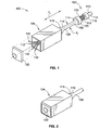
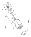
- Fig. 1 discloses a connector 100 for a hearing aid (not disclosed).
- the connector 100 comprises a plug 102, a receiver housing 104 and an interconnecting tube 106.
- the interconnecting tube 106 defines a first end 108 and a second end 110, and accommodates one or more accommodated elements 112.
- the accommodated elements 112 are provided in the form of electrical conductors.
- the interconnecting tube 106 is attached to the plug 102 and the receiver housing 104 e.g. by means of welding.
- the interconnecting tube 106, the plug 102 and the receiver housing 104 are provided. Subsequently, the accommodated elements 112 are inserted into the interconnecting tube 106, which is relatively wide, as it has not been elongated yet.
- the accommodated elements 112 are electrically connected to the terminals 113, prior to insertion of the accommodated elements 112 into the interconnecting tube 106.
- the terminals 113 are electrically (and physically) connected to the accommodated elements 112 after these elements 112 have been inserted into the interconnecting tube 106.
- the first end 108 and the second end 110 are forced in opposite directions, i.e. away from each other. This may be done by means of a tool which is adapted to abut the first inclined surface 114 and the second inclined surface 116, during application of the oppositely directed forces. This will cause the interconnecting tube 106 to be elongated, whereby the diameter of the interconnecting tube 106 decreases.
- the interconnecting tube 106 is shown in its elongated form in Fig. 3 .
- the interconnecting tube 106 Prior to the elongation process, the interconnecting tube 106 has a length L1 and a diameter d1, see Fig. 1 . Subsequently to the elongation process, the interconnecting tube 106 is longer and has a length L2. At the same time the width of the interconnecting tube 106 is smaller, as the interconnecting tube 106 now has the diameter d2. It will be appreciated that L2 is larger (longer) than L1 and that d1 is larger (wider) than d2. The different diameters are discussed in further detail in relation to Figs. 4a and 4b .
- the tools are adapted to abut each of the plug 102 and the receiver housing 104 during the elongation process.
- the accommodated elements 112 are prevented from being pulled into the interconnecting tube 106 during the elongation process. Instead the other end of the accommodated elements 112 are pulled into the interconnecting tube 106.
- the accommodated elements 112 in the opposite end are sufficiently long to ensure that at least a part of the accommodated elements 112 extend out of the receiver housing 104, both before and after the elongation process.
- end element 122 defining one or more terminals is fastened to the receiver housing 104, see Fig. 2 .
- the accommodated elements 112 are (electrically) connected to the terminals (not shown).
- Figs. 4a and 4b discloses a cross-section of the interconnecting tube 106 prior to the elongation ( Fig. 4a ) and after elongation ( Fig. 4b ).
- the width d1 of the interconnecting tube 106 in Fig. 4a is larger than the width d2 in Fig. 4b .
- the interconnecting tube 106 is wider prior to elongation than after elongation.
- the inner space 124 is larger before elongation. Accordingly, it is easier to insert the accommodated elements 112 into the inner space 124.
- the accommodated elements 112 are provided in the form of electrical conductors 126, a tube 128 forming a passage 129, and a reinforcing element 130.
- the electrical conductors 126 may be electrically connected to the terminals of the plug 102 and the receiver housing 104.
- the tube 128 form ing a passage 129 may be used as an audio/sound canal through which sound propagates during use of the connector 100.
- the reinforcing element 130 may serve the purpose of axially reinforcing the connector 100, such that it may withstand a larger axial force without breaking.
Landscapes
- Health & Medical Sciences (AREA)
- General Health & Medical Sciences (AREA)
- Neurosurgery (AREA)
- Otolaryngology (AREA)
- Physics & Mathematics (AREA)
- Engineering & Computer Science (AREA)
- Acoustics & Sound (AREA)
- Signal Processing (AREA)
- Connector Housings Or Holding Contact Members (AREA)
- Details Of Connecting Devices For Male And Female Coupling (AREA)
Claims (10)
- Verfahren zum Bilden eines Verbinders für ein Hörgerät, wobei der Verbinder einen Stecker, ein Schallerzeugergehäuse und einen Verbindungsschlauch umfasst, wobei der Verbindungsschlauch:- an dem Stecker und dem Schallerzeugergehäuse angebracht ist, oder der Stecker, das Schallerzeugergehäuse und der Verbindungsschlauch ein einstückiges Element sind,- ein erstes Ende und ein zweites Ende aufweist, und- darin ein oder mehrere aufgenommene Elemente aufnimmt,wobei das Verfahren folgende Schritte umfasst:- Bereitstellen des einen oder der mehreren aufgenommenen Elemente im Innern des Verbindungsschlauchs, und- Dehnen des Verbindungsschlauchs durch Auseinanderdrücken des ersten und des zweiten Endes des Verbindungsschlauchs, wodurch der Verbindungsschlauch verlängert wird und Breite/Durchmesser derselben reduziert wird.
- Verfahren nach Anspruch 1, wobei der Dehnungsschritt den Schritt des Auseinanderdrückens des Steckers und des Schallerzeugergehäuses umfasst, um die ersten und zweiten Enden des Verbindungsschlauchs auseinanderzudrücken, wodurch der Verbindungsschlauch verlängert wird.
- Verfahren nach Anspruch 1 oder 2, ferner umfassend den Schritt des Beendens des Dehnungsschritts, wenn eine vorbestimmte Spannung in dem Verbindungsschlauch erreicht wurde.
- Verfahren nach einem der vorhergehenden Ansprüche, ferner umfassend den Schritt des Beendens des Dehnungsschritts, wenn eine vorbestimmte Reibung zwischen dem Verbindungsschlauch und den aufgenommenen Elementen erreicht wurde.
- Verfahren nach einem der vorhergehenden Ansprüche, wobei das Verfahren ferner den Schritt des Beendens des Dehnungsschritts umfasst, wenn eine vorbestimmte Breite des Verbindungsschlauchs erreicht wurde.
- Verfahren nach einem der vorhergehenden Ansprüche, ferner umfassend den Schritt des Bereitstellens eines Reibungsreduzierungsmittels für eine innere Oberfläche des Verbindungsschlauchs und/oder eine äußere Oberfläche eines oder mehrerer der aufgenommenen Elemente, um die Reibung zwischen dem Verbindungsschlauch und den aufgenommenen Elementen während des Dehnungsschritts zu reduzieren.
- Verfahren nach einem der vorhergehenden Ansprüche, ferner umfassend den Schritt des Erhöhens der Temperatur des Verbindungsschlauchs und der aufgenommenen Elemente.
- Verfahren nach einem der vorhergehenden Ansprüche, wobei die aufgenommenen Elemente eines oder mehrere von einem elektrischen Leiter, eines passiven elektrischen Bauteils, eines aktiven elektrischen Bauteils, einer elektrischen Schaltung, eines Verstärkungselements, eines einen Durchgang bildenden Schlauchs und eines Lichtwellenleiters umfasst.
- Verfahren nach einem der vorhergehenden Ansprüche, wobei der Dehnungsschritt das nicht Verändern der Länge der aufgenommenen Elemente umfasst.
- Verbinder, der anhand des Verfahrens nach einem der Ansprüche 1 bis 9 hergestellt wird.
Applications Claiming Priority (1)
| Application Number | Priority Date | Filing Date | Title |
|---|---|---|---|
| US35218810P | 2010-06-07 | 2010-06-07 |
Publications (2)
| Publication Number | Publication Date |
|---|---|
| EP2393312A1 EP2393312A1 (de) | 2011-12-07 |
| EP2393312B1 true EP2393312B1 (de) | 2014-08-13 |
Family
ID=44118310
Family Applications (1)
| Application Number | Title | Priority Date | Filing Date |
|---|---|---|---|
| EP11168966.7A Not-in-force EP2393312B1 (de) | 2010-06-07 | 2011-06-07 | Verfahren zur Formung eines Verbinders für ein Hörgerät |
Country Status (3)
| Country | Link |
|---|---|
| US (1) | US20110299708A1 (de) |
| EP (1) | EP2393312B1 (de) |
| DK (1) | DK2393312T3 (de) |
Families Citing this family (64)
| Publication number | Priority date | Publication date | Assignee | Title |
|---|---|---|---|---|
| DE102009032981B4 (de) * | 2009-07-14 | 2013-11-28 | Siemens Medical Instruments Pte. Ltd. | Hörerschlauch |
| DE102011005630A1 (de) * | 2011-03-16 | 2012-09-20 | Siemens Medical Instruments Pte. Ltd. | Hydrophobes ABS Kunststoffmaterial für Gehäuse |
| DK2730097T3 (en) | 2011-07-07 | 2019-12-09 | Sonion Nederland Bv | A multiple receiver assembly and a method for assembly thereof |
| EP2723102B1 (de) | 2012-10-18 | 2018-09-05 | Sonion Nederland B.V. | Wandler, Hörgerät mit dem Wandler und Verfahren zum Betrieb des Wandlers |
| US9066187B2 (en) | 2012-10-18 | 2015-06-23 | Sonion Nederland Bv | Dual transducer with shared diaphragm |
| DK2747459T3 (en) | 2012-12-21 | 2018-12-17 | Sonion Nederland Bv | RIC unit with Thuras tube |
| DK2750413T3 (en) | 2012-12-28 | 2017-05-22 | Sonion Nederland Bv | Hearing aid |
| US9401575B2 (en) | 2013-05-29 | 2016-07-26 | Sonion Nederland Bv | Method of assembling a transducer assembly |
| DK2849463T3 (en) | 2013-09-16 | 2018-06-25 | Sonion Nederland Bv | Transducer with moisture transporting element |
| DK3550852T3 (en) | 2014-02-14 | 2021-02-01 | Sonion Nederland Bv | A joiner for a receiver assembly |
| EP2908559B1 (de) | 2014-02-18 | 2016-10-05 | Sonion A/S | Verfahren zur Herstellung von Anordnungen für Hörgeräte |
| EP2914018B1 (de) | 2014-02-26 | 2016-11-09 | Sonion Nederland B.V. | Lautsprecher, verankerung und verfahren |
| US9432774B2 (en) | 2014-04-02 | 2016-08-30 | Sonion Nederland B.V. | Transducer with a bent armature |
| EP2953380A1 (de) | 2014-06-04 | 2015-12-09 | Sonion Nederland B.V. | Akustische Übersprechkompensation |
| US9729974B2 (en) | 2014-12-30 | 2017-08-08 | Sonion Nederland B.V. | Hybrid receiver module |
| EP3051841B1 (de) | 2015-01-30 | 2020-10-07 | Sonion Nederland B.V. | Hörer mit aufgehängter motoranordnung |
| DK3057339T3 (da) | 2015-02-10 | 2021-01-04 | Sonion Nederland Bv | Mikrofonmodul med fælles midterste lydindgangsanordning |
| EP3073764B1 (de) | 2015-03-25 | 2021-04-21 | Sonion Nederland B.V. | Hörgerät mit einem einsatzelement |
| EP3073765B1 (de) | 2015-03-25 | 2022-08-17 | Sonion Nederland B.V. | Anordnung eines hörers in einem gehörgang mit einer membran und einer kabelverbindung |
| DK3133829T3 (da) | 2015-08-19 | 2020-06-22 | Sonion Nederland Bv | Lydgiverenhed med forbedret frekvensrespons |
| DK3139627T3 (da) | 2015-09-02 | 2019-05-20 | Sonion Nederland Bv | Høreanordning med flervejslydgivere |
| US9668065B2 (en) | 2015-09-18 | 2017-05-30 | Sonion Nederland B.V. | Acoustical module with acoustical filter |
| US10021494B2 (en) | 2015-10-14 | 2018-07-10 | Sonion Nederland B.V. | Hearing device with vibration sensitive transducer |
| DK3160157T3 (en) | 2015-10-21 | 2018-12-17 | Sonion Nederland Bv | Vibration-compensated vibroacoustic device |
| DK3177037T3 (en) | 2015-12-04 | 2020-10-26 | Sonion Nederland Bv | Balanced armature receiver with bi-stable balanced armature |
| DK3185584T3 (da) | 2015-12-21 | 2020-07-20 | Sonion Nederland Bv | Lydgiveranordning med en udpræget længderetning |
| EP3197046B1 (de) | 2016-01-25 | 2021-04-14 | Sonion Nederland B.V. | Selbstvorspannender ausgangsboosterverstärker und verwendung davon |
| EP3200479A3 (de) | 2016-01-28 | 2017-08-30 | Sonion Nederland B.V. | Elektrostatischer schallgenerator und anordnung mit elektrostatischem schallgenerator und transformator |
| EP3232685B1 (de) | 2016-04-13 | 2021-03-03 | Sonion Nederland B.V. | Kuppel für eine persönliche audio-nachrichtenvorrichtung |
| US10078097B2 (en) | 2016-06-01 | 2018-09-18 | Sonion Nederland B.V. | Vibration or acceleration sensor applying squeeze film damping |
| DK3279621T4 (da) | 2016-08-26 | 2025-04-28 | Sonion Nederland Bv | Vibrationssensor med lavfrekvent roll-off-responskurve |
| EP3293985B1 (de) | 2016-09-12 | 2021-03-24 | Sonion Nederland B.V. | Hörer mit integrierter membranbewegungserkennung |
| DK3313097T3 (da) | 2016-10-19 | 2020-10-19 | Sonion Nederland Bv | An ear bud or dome |
| EP3324645A1 (de) | 2016-11-18 | 2018-05-23 | Sonion Nederland B.V. | Phasenkorrigierendes system und phasenkorrigierbares wandlersystem |
| US20180145643A1 (en) | 2016-11-18 | 2018-05-24 | Sonion Nederland B.V. | Circuit for providing a high and a low impedance and a system comprising the circuit |
| EP3324538A1 (de) | 2016-11-18 | 2018-05-23 | Sonion Nederland B.V. | Messschaltung mit einer verstärkerschaltung |
| US10264361B2 (en) | 2016-11-18 | 2019-04-16 | Sonion Nederland B.V. | Transducer with a high sensitivity |
| EP3337184B1 (de) | 2016-12-14 | 2020-03-25 | Sonion Nederland B.V. | Anker und wandler mit dem anker |
| US10405085B2 (en) | 2016-12-16 | 2019-09-03 | Sonion Nederland B.V. | Receiver assembly |
| EP3337191B1 (de) | 2016-12-16 | 2021-05-19 | Sonion Nederland B.V. | Schallerzeugeranordnung |
| US10699833B2 (en) | 2016-12-28 | 2020-06-30 | Sonion Nederland B.V. | Magnet assembly |
| EP3342749A3 (de) | 2016-12-30 | 2018-09-12 | Sonion Nederland B.V. | Mikroelektromechanischer wandler |
| US10477308B2 (en) | 2016-12-30 | 2019-11-12 | Sonion Nederland B.V. | Circuit and a receiver comprising the circuit |
| DK3407625T3 (en) | 2017-05-26 | 2021-07-12 | Sonion Nederland Bv | Receiver with venting opening |
| US10721566B2 (en) | 2017-05-26 | 2020-07-21 | Sonion Nederland B.V. | Receiver assembly comprising an armature and a diaphragm |
| EP3429231B1 (de) | 2017-07-13 | 2023-01-25 | Sonion Nederland B.V. | Hörgerät mit einrichtung zur vibrationsvermeidung |
| EP3451688B1 (de) | 2017-09-04 | 2021-05-26 | Sonion Nederland B.V. | Schallerzeuger, abschirmung und öffnung |
| GB201714956D0 (en) | 2017-09-18 | 2017-11-01 | Sonova Ag | Hearing device with adjustable venting |
| EP3471437B1 (de) | 2017-10-16 | 2020-12-23 | Sonion Nederland B.V. | Ventil, wandler mit einem ventil, hörgerät und verfahren |
| DK3471432T3 (da) | 2017-10-16 | 2022-10-24 | Sonion Nederland Bv | Lydkanalelement med en ventil og en transducer med lydkanalelementet |
| US10945084B2 (en) | 2017-10-16 | 2021-03-09 | Sonion Nederland B.V. | Personal hearing device |
| DK3567873T3 (en) | 2018-02-06 | 2021-11-15 | Sonion Nederland Bv | Method for controlling an acoustic valve of a hearing device |
| DK3531720T3 (da) | 2018-02-26 | 2021-11-15 | Sonion Nederland Bv | Anordning af en lydgiver og en mikrofon |
| EP3531713B1 (de) | 2018-02-26 | 2022-11-02 | Sonion Nederland B.V. | Miniaturlautsprecher mit akustischer masse |
| EP3467457B1 (de) | 2018-04-30 | 2022-07-20 | Sonion Nederland B.V. | Vibrationssensor |
| DK3579578T3 (da) | 2018-06-07 | 2022-05-02 | Sonion Nederland Bv | Miniaturelydgiver |
| US10951169B2 (en) | 2018-07-20 | 2021-03-16 | Sonion Nederland B.V. | Amplifier comprising two parallel coupled amplifier units |
| DK3627856T3 (da) | 2018-09-19 | 2023-11-13 | Sonion Nederland Bv | Hus, der omfatter en sensor |
| EP4300995A3 (de) | 2018-12-19 | 2024-04-03 | Sonion Nederland B.V. | Miniaturlautsprecher mit mehreren schallhohlräumen |
| US11190880B2 (en) | 2018-12-28 | 2021-11-30 | Sonion Nederland B.V. | Diaphragm assembly, a transducer, a microphone, and a method of manufacture |
| EP3675522A1 (de) | 2018-12-28 | 2020-07-01 | Sonion Nederland B.V. | Miniaturlautsprecher ohne wesentliche akustische leckage |
| DE102019202651A1 (de) | 2019-02-27 | 2020-01-23 | Sivantos Pte. Ltd. | Schallschlauch und HdO-Hörgerät |
| EP3726855B1 (de) | 2019-04-15 | 2021-09-01 | Sonion Nederland B.V. | Persönliches hörgerät mit entlüftungskanal und akustischer trennung |
| EP3806494B1 (de) | 2019-10-07 | 2023-12-27 | Sonion Nederland B.V. | Hörgerät mit einem optischen sensor |
Family Cites Families (6)
| Publication number | Priority date | Publication date | Assignee | Title |
|---|---|---|---|---|
| US6426464B1 (en) * | 2000-10-10 | 2002-07-30 | The United States Of America As Represented By The Secretary Of The Navy | Cable sectional assembly which houses concatenated electronic modules |
| DE102004049010A1 (de) * | 2004-10-05 | 2006-04-20 | Bruckhoff Apparatebau Gmbh | Hörgerät |
| JP4836859B2 (ja) * | 2006-04-20 | 2011-12-14 | リオン株式会社 | 耳かけ形補聴器 |
| DE102006046698B4 (de) * | 2006-10-02 | 2011-06-16 | Siemens Audiologische Technik Gmbh | Schallleiter und Hörvorrichtung |
| CN101884229A (zh) * | 2007-10-16 | 2010-11-10 | 埃斯特纶股份公司 | 听力设备的挠性连接器 |
| US8023674B2 (en) * | 2008-09-17 | 2011-09-20 | Daniel R. Schumaier | Connector for hearing assistance device having reduced mechanical feedback |
-
2011
- 2011-06-07 EP EP11168966.7A patent/EP2393312B1/de not_active Not-in-force
- 2011-06-07 US US13/154,988 patent/US20110299708A1/en not_active Abandoned
- 2011-06-07 DK DK11168966.7T patent/DK2393312T3/da active
Also Published As
| Publication number | Publication date |
|---|---|
| EP2393312A1 (de) | 2011-12-07 |
| DK2393312T3 (da) | 2014-10-27 |
| US20110299708A1 (en) | 2011-12-08 |
Similar Documents
| Publication | Publication Date | Title |
|---|---|---|
| EP2393312B1 (de) | Verfahren zur Formung eines Verbinders für ein Hörgerät | |
| US8454385B2 (en) | Coaxial cable connector with strain relief clamp | |
| CN203942061U (zh) | 连接端子和电连接器 | |
| US8575490B2 (en) | Spacer for use in a flat cable | |
| EP2736268A1 (de) | Kopfhörerkabelstruktur | |
| EP2521379A1 (de) | Hörgerät | |
| EP4207503A4 (de) | Leiterstruktur und elektrisches verbindungsmodul | |
| US8647155B2 (en) | Electrical-conductive assembly for signal cable | |
| CN101449339A (zh) | 自动折叠电缆 | |
| EP2293437A3 (de) | Verfahren zur Bereitstellung von elektrostatischem Breitbandentladungsschutz und damit erhaltene Schaltungen | |
| US8011971B2 (en) | Adjustable plug and earphone utilizing the same | |
| CN103138137B (zh) | 电连接线、生产电连接线的方法及助听器 | |
| EP1253692A1 (de) | Mittelspannungskabelendverschluss | |
| JP6594777B2 (ja) | 接続装置、その組立体、およびその接続方法 | |
| JP6168923B2 (ja) | ワイヤーハーネスの接続構造および接続方法 | |
| JP5914258B2 (ja) | エポキシユニット及びポリマー套管 | |
| CN106981795B (zh) | 具有热收缩套管的线缆-连接器组件 | |
| US9106002B2 (en) | Method for sealing an electrical coupling piece, and coupling piece | |
| US20040152370A1 (en) | Terminal of a medium voltage electrical cable | |
| JP6577986B2 (ja) | 互いに電気接続させることができる複数のモジュールを有するモジュラーシステム | |
| KR20120002984U (ko) | 이어폰 보호캡 | |
| US10250005B2 (en) | Cable installation aid for multi-strand electrical conductors | |
| US20160164234A1 (en) | Earphone socket, earphone plug, earphone and electronic device | |
| JP5238016B2 (ja) | 接続母線 | |
| KR101167912B1 (ko) | 이어폰 |
Legal Events
| Date | Code | Title | Description |
|---|---|---|---|
| AK | Designated contracting states |
Kind code of ref document: A1 Designated state(s): AL AT BE BG CH CY CZ DE DK EE ES FI FR GB GR HR HU IE IS IT LI LT LU LV MC MK MT NL NO PL PT RO RS SE SI SK SM TR |
|
| AX | Request for extension of the european patent |
Extension state: BA ME |
|
| PUAI | Public reference made under article 153(3) epc to a published international application that has entered the european phase |
Free format text: ORIGINAL CODE: 0009012 |
|
| 17P | Request for examination filed |
Effective date: 20120608 |
|
| 17Q | First examination report despatched |
Effective date: 20130325 |
|
| GRAP | Despatch of communication of intention to grant a patent |
Free format text: ORIGINAL CODE: EPIDOSNIGR1 |
|
| INTG | Intention to grant announced |
Effective date: 20140224 |
|
| GRAS | Grant fee paid |
Free format text: ORIGINAL CODE: EPIDOSNIGR3 |
|
| GRAA | (expected) grant |
Free format text: ORIGINAL CODE: 0009210 |
|
| AK | Designated contracting states |
Kind code of ref document: B1 Designated state(s): AL AT BE BG CH CY CZ DE DK EE ES FI FR GB GR HR HU IE IS IT LI LT LU LV MC MK MT NL NO PL PT RO RS SE SI SK SM TR |
|
| REG | Reference to a national code |
Ref country code: GB Ref legal event code: FG4D |
|
| REG | Reference to a national code |
Ref country code: AT Ref legal event code: REF Ref document number: 682838 Country of ref document: AT Kind code of ref document: T Effective date: 20140815 Ref country code: CH Ref legal event code: EP |
|
| REG | Reference to a national code |
Ref country code: IE Ref legal event code: FG4D |
|
| REG | Reference to a national code |
Ref country code: CH Ref legal event code: NV Representative=s name: MICHELI AND CIE SA, CH |
|
| REG | Reference to a national code |
Ref country code: DE Ref legal event code: R096 Ref document number: 602011009005 Country of ref document: DE Effective date: 20141002 |
|
| REG | Reference to a national code |
Ref country code: DK Ref legal event code: T3 Effective date: 20141022 |
|
| REG | Reference to a national code |
Ref country code: NL Ref legal event code: VDEP Effective date: 20140813 |
|
| REG | Reference to a national code |
Ref country code: AT Ref legal event code: MK05 Ref document number: 682838 Country of ref document: AT Kind code of ref document: T Effective date: 20140813 |
|
| REG | Reference to a national code |
Ref country code: LT Ref legal event code: MG4D |
|
| PG25 | Lapsed in a contracting state [announced via postgrant information from national office to epo] |
Ref country code: GR Free format text: LAPSE BECAUSE OF FAILURE TO SUBMIT A TRANSLATION OF THE DESCRIPTION OR TO PAY THE FEE WITHIN THE PRESCRIBED TIME-LIMIT Effective date: 20141114 Ref country code: PT Free format text: LAPSE BECAUSE OF FAILURE TO SUBMIT A TRANSLATION OF THE DESCRIPTION OR TO PAY THE FEE WITHIN THE PRESCRIBED TIME-LIMIT Effective date: 20141215 Ref country code: NO Free format text: LAPSE BECAUSE OF FAILURE TO SUBMIT A TRANSLATION OF THE DESCRIPTION OR TO PAY THE FEE WITHIN THE PRESCRIBED TIME-LIMIT Effective date: 20141113 Ref country code: BG Free format text: LAPSE BECAUSE OF FAILURE TO SUBMIT A TRANSLATION OF THE DESCRIPTION OR TO PAY THE FEE WITHIN THE PRESCRIBED TIME-LIMIT Effective date: 20141113 Ref country code: SE Free format text: LAPSE BECAUSE OF FAILURE TO SUBMIT A TRANSLATION OF THE DESCRIPTION OR TO PAY THE FEE WITHIN THE PRESCRIBED TIME-LIMIT Effective date: 20140813 Ref country code: FI Free format text: LAPSE BECAUSE OF FAILURE TO SUBMIT A TRANSLATION OF THE DESCRIPTION OR TO PAY THE FEE WITHIN THE PRESCRIBED TIME-LIMIT Effective date: 20140813 Ref country code: LT Free format text: LAPSE BECAUSE OF FAILURE TO SUBMIT A TRANSLATION OF THE DESCRIPTION OR TO PAY THE FEE WITHIN THE PRESCRIBED TIME-LIMIT Effective date: 20140813 Ref country code: ES Free format text: LAPSE BECAUSE OF FAILURE TO SUBMIT A TRANSLATION OF THE DESCRIPTION OR TO PAY THE FEE WITHIN THE PRESCRIBED TIME-LIMIT Effective date: 20140813 |
|
| PG25 | Lapsed in a contracting state [announced via postgrant information from national office to epo] |
Ref country code: CY Free format text: LAPSE BECAUSE OF FAILURE TO SUBMIT A TRANSLATION OF THE DESCRIPTION OR TO PAY THE FEE WITHIN THE PRESCRIBED TIME-LIMIT Effective date: 20140813 Ref country code: HR Free format text: LAPSE BECAUSE OF FAILURE TO SUBMIT A TRANSLATION OF THE DESCRIPTION OR TO PAY THE FEE WITHIN THE PRESCRIBED TIME-LIMIT Effective date: 20140813 Ref country code: IS Free format text: LAPSE BECAUSE OF FAILURE TO SUBMIT A TRANSLATION OF THE DESCRIPTION OR TO PAY THE FEE WITHIN THE PRESCRIBED TIME-LIMIT Effective date: 20141213 Ref country code: RS Free format text: LAPSE BECAUSE OF FAILURE TO SUBMIT A TRANSLATION OF THE DESCRIPTION OR TO PAY THE FEE WITHIN THE PRESCRIBED TIME-LIMIT Effective date: 20140813 Ref country code: AT Free format text: LAPSE BECAUSE OF FAILURE TO SUBMIT A TRANSLATION OF THE DESCRIPTION OR TO PAY THE FEE WITHIN THE PRESCRIBED TIME-LIMIT Effective date: 20140813 Ref country code: LV Free format text: LAPSE BECAUSE OF FAILURE TO SUBMIT A TRANSLATION OF THE DESCRIPTION OR TO PAY THE FEE WITHIN THE PRESCRIBED TIME-LIMIT Effective date: 20140813 |
|
| PG25 | Lapsed in a contracting state [announced via postgrant information from national office to epo] |
Ref country code: NL Free format text: LAPSE BECAUSE OF FAILURE TO SUBMIT A TRANSLATION OF THE DESCRIPTION OR TO PAY THE FEE WITHIN THE PRESCRIBED TIME-LIMIT Effective date: 20140813 |
|
| PG25 | Lapsed in a contracting state [announced via postgrant information from national office to epo] |
Ref country code: RO Free format text: LAPSE BECAUSE OF FAILURE TO SUBMIT A TRANSLATION OF THE DESCRIPTION OR TO PAY THE FEE WITHIN THE PRESCRIBED TIME-LIMIT Effective date: 20140813 Ref country code: EE Free format text: LAPSE BECAUSE OF FAILURE TO SUBMIT A TRANSLATION OF THE DESCRIPTION OR TO PAY THE FEE WITHIN THE PRESCRIBED TIME-LIMIT Effective date: 20140813 Ref country code: SK Free format text: LAPSE BECAUSE OF FAILURE TO SUBMIT A TRANSLATION OF THE DESCRIPTION OR TO PAY THE FEE WITHIN THE PRESCRIBED TIME-LIMIT Effective date: 20140813 Ref country code: IT Free format text: LAPSE BECAUSE OF FAILURE TO SUBMIT A TRANSLATION OF THE DESCRIPTION OR TO PAY THE FEE WITHIN THE PRESCRIBED TIME-LIMIT Effective date: 20140813 Ref country code: CZ Free format text: LAPSE BECAUSE OF FAILURE TO SUBMIT A TRANSLATION OF THE DESCRIPTION OR TO PAY THE FEE WITHIN THE PRESCRIBED TIME-LIMIT Effective date: 20140813 |
|
| REG | Reference to a national code |
Ref country code: DE Ref legal event code: R097 Ref document number: 602011009005 Country of ref document: DE |
|
| PG25 | Lapsed in a contracting state [announced via postgrant information from national office to epo] |
Ref country code: PL Free format text: LAPSE BECAUSE OF FAILURE TO SUBMIT A TRANSLATION OF THE DESCRIPTION OR TO PAY THE FEE WITHIN THE PRESCRIBED TIME-LIMIT Effective date: 20140813 |
|
| PLBE | No opposition filed within time limit |
Free format text: ORIGINAL CODE: 0009261 |
|
| STAA | Information on the status of an ep patent application or granted ep patent |
Free format text: STATUS: NO OPPOSITION FILED WITHIN TIME LIMIT |
|
| 26N | No opposition filed |
Effective date: 20150515 |
|
| PG25 | Lapsed in a contracting state [announced via postgrant information from national office to epo] |
Ref country code: SI Free format text: LAPSE BECAUSE OF FAILURE TO SUBMIT A TRANSLATION OF THE DESCRIPTION OR TO PAY THE FEE WITHIN THE PRESCRIBED TIME-LIMIT Effective date: 20140813 |
|
| PG25 | Lapsed in a contracting state [announced via postgrant information from national office to epo] |
Ref country code: MC Free format text: LAPSE BECAUSE OF FAILURE TO SUBMIT A TRANSLATION OF THE DESCRIPTION OR TO PAY THE FEE WITHIN THE PRESCRIBED TIME-LIMIT Effective date: 20140813 |
|
| PG25 | Lapsed in a contracting state [announced via postgrant information from national office to epo] |
Ref country code: LU Free format text: LAPSE BECAUSE OF FAILURE TO SUBMIT A TRANSLATION OF THE DESCRIPTION OR TO PAY THE FEE WITHIN THE PRESCRIBED TIME-LIMIT Effective date: 20150607 |
|
| REG | Reference to a national code |
Ref country code: IE Ref legal event code: MM4A |
|
| REG | Reference to a national code |
Ref country code: FR Ref legal event code: ST Effective date: 20160229 |
|
| PG25 | Lapsed in a contracting state [announced via postgrant information from national office to epo] |
Ref country code: IE Free format text: LAPSE BECAUSE OF NON-PAYMENT OF DUE FEES Effective date: 20150607 |
|
| PG25 | Lapsed in a contracting state [announced via postgrant information from national office to epo] |
Ref country code: FR Free format text: LAPSE BECAUSE OF NON-PAYMENT OF DUE FEES Effective date: 20150630 |
|
| PG25 | Lapsed in a contracting state [announced via postgrant information from national office to epo] |
Ref country code: BE Free format text: LAPSE BECAUSE OF FAILURE TO SUBMIT A TRANSLATION OF THE DESCRIPTION OR TO PAY THE FEE WITHIN THE PRESCRIBED TIME-LIMIT Effective date: 20140813 |
|
| PG25 | Lapsed in a contracting state [announced via postgrant information from national office to epo] |
Ref country code: MT Free format text: LAPSE BECAUSE OF FAILURE TO SUBMIT A TRANSLATION OF THE DESCRIPTION OR TO PAY THE FEE WITHIN THE PRESCRIBED TIME-LIMIT Effective date: 20140813 |
|
| PG25 | Lapsed in a contracting state [announced via postgrant information from national office to epo] |
Ref country code: HU Free format text: LAPSE BECAUSE OF FAILURE TO SUBMIT A TRANSLATION OF THE DESCRIPTION OR TO PAY THE FEE WITHIN THE PRESCRIBED TIME-LIMIT; INVALID AB INITIO Effective date: 20110607 Ref country code: SM Free format text: LAPSE BECAUSE OF FAILURE TO SUBMIT A TRANSLATION OF THE DESCRIPTION OR TO PAY THE FEE WITHIN THE PRESCRIBED TIME-LIMIT Effective date: 20140813 |
|
| PG25 | Lapsed in a contracting state [announced via postgrant information from national office to epo] |
Ref country code: TR Free format text: LAPSE BECAUSE OF FAILURE TO SUBMIT A TRANSLATION OF THE DESCRIPTION OR TO PAY THE FEE WITHIN THE PRESCRIBED TIME-LIMIT Effective date: 20140813 |
|
| PG25 | Lapsed in a contracting state [announced via postgrant information from national office to epo] |
Ref country code: MK Free format text: LAPSE BECAUSE OF FAILURE TO SUBMIT A TRANSLATION OF THE DESCRIPTION OR TO PAY THE FEE WITHIN THE PRESCRIBED TIME-LIMIT Effective date: 20140813 |
|
| PG25 | Lapsed in a contracting state [announced via postgrant information from national office to epo] |
Ref country code: AL Free format text: LAPSE BECAUSE OF FAILURE TO SUBMIT A TRANSLATION OF THE DESCRIPTION OR TO PAY THE FEE WITHIN THE PRESCRIBED TIME-LIMIT Effective date: 20140813 |
|
| PGFP | Annual fee paid to national office [announced via postgrant information from national office to epo] |
Ref country code: DE Payment date: 20210511 Year of fee payment: 11 |
|
| PGFP | Annual fee paid to national office [announced via postgrant information from national office to epo] |
Ref country code: GB Payment date: 20210512 Year of fee payment: 11 Ref country code: CH Payment date: 20210616 Year of fee payment: 11 Ref country code: DK Payment date: 20210610 Year of fee payment: 11 |
|
| REG | Reference to a national code |
Ref country code: DE Ref legal event code: R119 Ref document number: 602011009005 Country of ref document: DE |
|
| REG | Reference to a national code |
Ref country code: DK Ref legal event code: EBP Effective date: 20220630 |
|
| REG | Reference to a national code |
Ref country code: CH Ref legal event code: PL |
|
| GBPC | Gb: european patent ceased through non-payment of renewal fee |
Effective date: 20220607 |
|
| PG25 | Lapsed in a contracting state [announced via postgrant information from national office to epo] |
Ref country code: LI Free format text: LAPSE BECAUSE OF NON-PAYMENT OF DUE FEES Effective date: 20220630 Ref country code: CH Free format text: LAPSE BECAUSE OF NON-PAYMENT OF DUE FEES Effective date: 20220630 |
|
| PG25 | Lapsed in a contracting state [announced via postgrant information from national office to epo] |
Ref country code: GB Free format text: LAPSE BECAUSE OF NON-PAYMENT OF DUE FEES Effective date: 20220607 Ref country code: DE Free format text: LAPSE BECAUSE OF NON-PAYMENT OF DUE FEES Effective date: 20230103 |
|
| PG25 | Lapsed in a contracting state [announced via postgrant information from national office to epo] |
Ref country code: DK Free format text: LAPSE BECAUSE OF NON-PAYMENT OF DUE FEES Effective date: 20220630 |