EP2394505B1 - Machine de fenaison - Google Patents
Machine de fenaison Download PDFInfo
- Publication number
- EP2394505B1 EP2394505B1 EP11001672A EP11001672A EP2394505B1 EP 2394505 B1 EP2394505 B1 EP 2394505B1 EP 11001672 A EP11001672 A EP 11001672A EP 11001672 A EP11001672 A EP 11001672A EP 2394505 B1 EP2394505 B1 EP 2394505B1
- Authority
- EP
- European Patent Office
- Prior art keywords
- haymaking machine
- machine according
- ground
- cantilever arms
- raking
- Prior art date
- Legal status (The legal status is an assumption and is not a legal conclusion. Google has not performed a legal analysis and makes no representation as to the accuracy of the status listed.)
- Active
Links
Images






Classifications
-
- A—HUMAN NECESSITIES
- A01—AGRICULTURE; FORESTRY; ANIMAL HUSBANDRY; HUNTING; TRAPPING; FISHING
- A01D—HARVESTING; MOWING
- A01D78/00—Haymakers with tines moving with respect to the machine
- A01D78/08—Haymakers with tines moving with respect to the machine with tine-carrying rotary heads or wheels
- A01D78/10—Haymakers with tines moving with respect to the machine with tine-carrying rotary heads or wheels the tines rotating about a substantially vertical axis
- A01D78/1007—Arrangements to facilitate transportation specially adapted therefor
- A01D78/1014—Folding frames
Definitions
- the invention relates to a hay-making machine according to the preamble of independent claim 1.
- the invention relates to a haymaking machine, in particular for the swathing of agricultural stalk material, with six circumferentially driven, supportable via support wheels on the ground, and over cantilevers from a working and operating position in a tilted transport position convertible rotary rakes, in the direction of travel substantially in v shaped arrangement.
- a haymaking machine of the aforementioned type is for example from the EP 1 488 685 A1 known.
- six rake rotors are provided in the direction of travel in a substantially V-shaped arrangement, which are guided on hinged cross arms and which are also supported on V-shaped swing-in and out longitudinal boom, and wherein three mutually associated rotary rake in the direction of travel on both sides of a drawbar arranged one behind the other.
- the two foremost in the direction of travel upstream rotary rakes determine the maximum working width and they are located in front of a steered or unguided machine axis.
- To transfer to their transport position the respective rotary rake are to be pivoted inwardly by means of the longitudinal arm.
- the rotary rakes are supported on these arms on a length-adjustable drawbar, which allow the outer rotary rake in one supported by support wheels having trolleys relative to the ground, with a machine frame, which consists of a central drawbar and two of this drawbar scissor-like, at least about vertical pivot axes between a working and operating position and a transport position convertible pivot bar for receiving the rotary rakes, constructed for articulation of the rotary rakes on the pivot bar further arms are provided which are pivotable between an approximately horizontal working position and an approximately vertical transport position, wherein the pivot bars are associated with handlebars, which are pivotally hinged at one end to the central drawbar and by the during pivotal movement of the pivoting bar automatically the orientation of the boom with respect to the pivot bar is changeable.
- the object of the invention is to propose an improved haymaking machine of the type described above, with the aim of achieving the lowest possible length of hitch, both in the working and in the transport journey and thereby improved steering characteristics for the trailer towing vehicle with hitchhiking machine attached, which also To provide an improved visual control of the outer rake for the operator in the working drive with less technical effort.
- the scissor-like from a central draw bar and two drawbar associated, at least about vertical pivot axes between a working and operating position and a transport position convertible pivot bar for receiving the rotary rakes, is constructed for articulation of the rotary rakes on the pivot bar further arms are provided which are pivotable between an approximately horizontal working position and an approximately vertical transport position, wherein the pivot bars are associated with handlebars, which are pivotally hinged at one end to the central drawbar and by the during pivotal movement of the pivoting bar automatically the orientation of the boom with respect to the pivot bar is changeable.
- the object of the invention is to propose an improved haymaking machine of the type described above, with the aim of achieving the lowest possible length of hitch, both in the working and in the transport journey and thereby improved steering characteristics for the trailer towing vehicle with attached hay-making machine, which also To provide an improved visual control of the outer rake for the operator in the working drive with less technical effort.
- the outer rotary rake are hinged to arms, which are at the same time horizontally and vertically pivotable boom, and at the same time represent an extension of the V-shaped longitudinally pivoting carrier, it is possible, the outer rotary rake in conjunction with the pivoting action of the longitudinal boom either outward in to pivot a working position near the ground and to determine the working width or, conversely, to pivot into a transport position away from the ground such that the outer rotary top essentially lies at a height above the drawbar and the longitudinal tension bar, at the same time occupying a position between the two side rails and at the same time At least partially occupy the space in their spatial extent between the also folded up and lying behind in the direction of travel rotary rakes.
- This embodiment of the pivoting mechanism of the outer rotary rake allows an optimally short length of the drawbar and coupled thereto also a short overall length, both in the working and in the transport position of the haymaking machine, whereby the inventive task is realized. Further advantageous embodiments of the invention are shown in the embodiment described below.
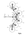
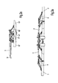
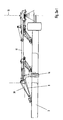
- Fig.1 to Fig. 3 is a haymaking machine according to the invention, designed as a six-rotor rake, shown according to the rules of technical drawing in the classical representation of front view, side view and top view on a sheet. It puts Fig.2 the front view, Fig.1 the top view and Figure 3 the side view, however, seen without towing vehicle against the direction of travel F. This representation is maintained in the following figures the essence of this representation accordingly.
- Fig. 1, Fig.2 and Fig.3 show a six-rotor rake 2 according to the invention in working position with a towing vehicle 43.
- the direction of travel is marked with the direction of travel arrow F.
- the six-rotor rake 2 essentially comprises the outer rotary rake 3,3 ', the middle rotary rake 4,4' and the inner rotary rake 5.5 ', the outer boom 6,6', the middle boom 7,7 ', the inner boom 8,8 ', the longitudinal member 9,9', the drawbar 11 with its connection device 10 for coupling to the towing vehicle 43 and the chassis 13, on which the largest proportion of the weight of the six-rotor rake 2 is supported on the ground.
- the 1a shows an enlarged view of Fig. 1 without towing vehicle and further enlarged details from the 1a are the figure representations 1a-1 and Fig. 1a-2 refer to.
- Analog shows the 2a an enlarged view of Fig. 2
- Fig. 3a an enlarged view of Fig. 3 , where the figures 3a-1 and 3a-2 also further enlarged details of 3a can be seen.
- the middle boom 7,7 'and the inner boom 8,8' are articulated in known hinged joints 16,16'17,17 'on the longitudinal beams 9,9', so that the rotary rake 4,4'.5 , 5 'in a per se also known manner from a ground-level working position in a ground-away transport position and vice versa by a pivoting movement about the horizontal pivot axes 18,18' of the folding joints 16,16'17,17 'pivot.
- the longitudinal members 9,9 ' are pivotally connected to the drawbar 11 via a coupling mechanism 23, consisting of the coupling elements 24,24'; 25,25 ' connected.
- the coupling elements 24,24 ' are in the pivot joints 26,26' with the longitudinal beams 9,9 'and in the hinges 27,27' with a sliding joint 28 which is slidably mounted on the drawbar 11, connected. End of the drawbar 11, the coupling elements 25,25 'in the hinges 30,30' and the longitudinal beams 9,9 'in the hinges 29,29' posted.
- the coupling mechanism 23 has in principle two drive members, wherein the first drive member consists of the hydraulic cylinder 22, the cylinder housing is struck on the drawbar 11 and the piston rod head on the sliding joint 28, and wherein the second drive member consisting of two hydraulic cylinders 31,31 'on the one hand Drawbar 11 is hinged in the hinges 32,32 'and on the other hand to the coupling elements in the hinges 33,33'.
- the first drive member or the hydraulic cylinder 22 With the first drive member or the hydraulic cylinder 22, the drawbars 9,9 'about the pivot joints 29,29' and with the second drive member or the hydraulic cylinder 31,31 ', the longitudinal beams 9,9' at the same time about the pivot joints 29,29 'and 30,30' are pivoted.
- Fig.1b is the front view
- Fig. 1b the top view
- 3b the side view of the rotary rake 2.
- FIGURE 1b shows shows one Intermediate position of the haymaking machine for transfer to the transport position and FIGURE 1b-1 shows an enlarged view of a section 1b shows , and continues to show 1b shows 1-2 again an enlarged section FIGURE 1b-1 ,
- These figures illustrate the changed position of the coupling elements 24,24 'and 25,25' .des the coupling gear 23 against the working and operating position accordingly 1a-1 ,
- the piston rod 38 By the pressurization of the hydraulic cylinder 22 on the piston bottom side moves the piston rod 38 out of the cylinder housing 34 and moves the guide carriage 37, which is also formed as a thrust joint 28 formed by the drawbar 11 in a prismatic guide, along the drawbar 11 in the direction F.
- the thus enforced movement form of the linkage 23 causes the side members 9,9 'perform a pivoting movement in the direction of drawbar 11 about the hinge points 29,29' and wherein the hinge points 29,29 'itself also a pivotal movement in the direction of drawbar 11 and at the same time opposite the direction of travel F run.
- the rotary rakes 4, 4 ', 5, 5', 6, 6 'thus become simultaneously pivoted in the direction of the drawbar 11 and counter to the direction of travel F.
- FIG. 1c is the front view
- Fig. 1c the top view
- 3 c The side view of the six-rotor rake 2 is shown.
- the progressing process of transfer of the rotary rake 2 is shown following the illustrated situation according to the figure representations Fig.1b to Fig.3b , In the illustrated situation, all rotary rake 3,3 ', 4,4', 5,5 'folded up with their arms in a conventional manner to their horizontal folding axes.
- FIG. 1d is the front view
- Fig. 1d the top view
- 3 d the side view of the six-rotor rake 2. Shown is the further progressing process of transfer of the six-rotor rake 2 following the situation shown in the figure representations Fig.1c to Fig.3c , After folding up the outer rotary rake 3,3 'according to the embodiments of the figures Fig.
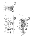
- Fig. 4 shows the rotary windrower 2 now in its final transport position with biased towing vehicle 43rd Wie der Figure 2f it can be seen, were in the presentation, the support wheels 14,14 'still in the ground engagement position, ie they still have contact with the ground 42 as footprint of the chassis 13. In Figure 4 In contrast, the support wheels 14,14 'are folded into their final transport position also, so that they provide no contribution to the transport width on the one hand and the other hand, the rotary windrower is a pure Einachsigen trailer.
- This inventive embodiment of the haymaking machine 1 and the rotary rake 2 results in a short transport length 46 but also a short length G in the unfolded working position, which allows good steering properties without the need for a steerable chassis 13 and which thereby significantly reduces the technical complexity and thus contributes to improved efficiency of the haymaking machines.
- This embodiment also allows for the operator an improved visual visual inspection of the outer rotary rake 3,3 'during the working journey, since the outer rake rotary 3,3' are closer to the towing vehicle 43.
Landscapes
- Life Sciences & Earth Sciences (AREA)
- Environmental Sciences (AREA)
- Agricultural Machines (AREA)
- Soil Working Implements (AREA)
Claims (14)
- Machine de fenaison, en particulier pour l'andainage de produit agricole en tiges, comportant six rotors de râtelage entraînés en rotation et pouvant être supportés sur le sol par des roues d'appui ainsi que déplacés par des bras porteurs d'une position de travail et de service vers une position de transport basculée, les bras porteurs des rotors de râtelage étant articulés de manière rabattable sur des longerons intérieurs pouvant pivoter horizontalement en forme de V, et, dans la position de travail et de service, les rotors de râtelage étant orientés les uns par rapport aux autres sensiblement en forme de V dans la direction de marche, caractérisée en ce que les rotors de râtelage extérieurs (3, 3') qui déterminent la largeur de travail (A) sont articulés sur des bras porteurs extérieurs (6, 6') et les bras porteurs extérieurs (6, 6') sont articulés de manière pivotante horizontalement et verticalement dans des articulations pivotantes biaxiales (19, 19') sur les longerons (9, 9') pouvant pivoter horizontalement en forme de V, de sorte que les rotors de râtelage extérieurs (3, 3') prennent une position de transport des deux côtés de la poutre d'attelage (11) et, en même temps, entre les deux longerons (9, 9').
- Machine de fenaison selon la revendication 1, caractérisée en ce que, dans leur position de travail, les bras porteurs extérieurs (6, 6') forment sensiblement un prolongement de l'extension longitudinale des longerons (9, 9').
- Machine de fenaison selon la revendication 1, caractérisée en ce que les bras porteurs extérieurs (6, 6') sont articulés sur leurs longerons (9, 9') par une articulation pivotante biaxiale (19, 19') qui présente un premier axe de pivotement (20) comme axe de pivotement horizontal et un deuxième axe de pivotement (21) comme axe de pivotement vertical.
- Machine de fenaison selon la revendication 1, caractérisée en ce que les bras porteurs extérieurs (6, 6') peuvent effectuer deux mouvements de pivotement dans des plans de pivotement différents, et chaque rotor de râtelage extérieur (3, 3') peut être basculé, autour de son axe de pivotement horizontal (20), d'une première position proche du sol vers une première position éloignée du sol et, autour de son deuxième axe de pivotement (21) vertical, vers une deuxième position éloignée du sol formant la position de transport définitive.
- Machine de fenaison selon la revendication 1, caractérisée en ce que, dans leur position de transport, les rotors de râtelage (3, 3') se trouvent au moins partiellement entre les rotors de râtelage intermédiaires (4, 4') voisins et relevés.
- Machine de fenaison selon la revendication 1, caractérisée en ce que, dans leur position de transport, les rotors de râtelage extérieurs se trouvent sensiblement au-dessus de la poutre d'attelage (11).
- Machine de fenaison selon les revendications 1 et 2, caractérisée en ce que le premier et le deuxième axe de pivotement (20, 21) de l'articulation pivotante biaxiale (19, 19') s'étendent de manière sécante ou oblique l'un par rapport à l'autre.
- Machine de fenaison selon les revendications 1 et 2, caractérisée en ce que les longerons (9, 9') présentent un coude horizontal (α) dans leur extension longitudinale.
- Machine de fenaison selon les revendications 1 et 2, caractérisée en ce que les longerons (9, 9') présentent une roue d'appui pouvant être déplacée d'une position proche du sol vers une position éloignée du sol.
- Machine de fenaison selon les revendications 1 et 2, caractérisée en ce que, à une extrémité, les longerons (9, 9') sont articulés avec la poutre d'attelage (11) au moyen d'éléments de couplage (12, 12').
- Machine de fenaison selon la revendication 9, caractérisée en ce que les bras porteurs extérieurs (6, 6') peuvent pivoter autour des points d'articulation de leurs éléments de couplage (12, 12') selon le principe d'un mécanisme articulé.
- Machine de fenaison selon les revendications 9 et 10, caractérisée en ce que les éléments de couplage (12, 12') peuvent déplacer les rotors de râtelage (4, 4', 5, 5', 6, 6') de manière pivotante par rapport à la poutre d'attelage (11).
- Machine de fenaison selon la revendication 11, caractérisée en ce que les rotors de râtelage (4, 4', 5, 5', 6, 6') sont mobiles en pivotement par rapport à la direction de marche (F).
- Machine de fenaison selon la revendication 11, caractérisée en ce que les rotors de râtelage (4, 4', 5, 5', 6, 6') sont mobiles en pivotement transversalement à la direction de marche (F), ce qui permet de faire varier la largeur de l'andain (B).
Priority Applications (2)
| Application Number | Priority Date | Filing Date | Title |
|---|---|---|---|
| SI201130024T SI2394505T1 (sl) | 2010-06-12 | 2011-03-01 | Stroj za zgrabljanje sena |
| PL11001672T PL2394505T3 (pl) | 2010-06-12 | 2011-03-01 | Maszyna do zbioru pokosu |
Applications Claiming Priority (1)
| Application Number | Priority Date | Filing Date | Title |
|---|---|---|---|
| DE102010023573A DE102010023573A1 (de) | 2010-06-12 | 2010-06-12 | Heuwerbungsmaschine |
Publications (2)
| Publication Number | Publication Date |
|---|---|
| EP2394505A1 EP2394505A1 (fr) | 2011-12-14 |
| EP2394505B1 true EP2394505B1 (fr) | 2013-02-13 |
Family
ID=44202058
Family Applications (1)
| Application Number | Title | Priority Date | Filing Date |
|---|---|---|---|
| EP11001672A Active EP2394505B1 (fr) | 2010-06-12 | 2011-03-01 | Machine de fenaison |
Country Status (5)
| Country | Link |
|---|---|
| EP (1) | EP2394505B1 (fr) |
| DE (1) | DE102010023573A1 (fr) |
| DK (1) | DK2394505T3 (fr) |
| PL (1) | PL2394505T3 (fr) |
| SI (1) | SI2394505T1 (fr) |
Families Citing this family (1)
| Publication number | Priority date | Publication date | Assignee | Title |
|---|---|---|---|---|
| FR3082389B1 (fr) * | 2018-06-18 | 2020-11-20 | Kuhn Sa | Machine de fenaison avec largeur de projection controlee |
Family Cites Families (3)
| Publication number | Priority date | Publication date | Assignee | Title |
|---|---|---|---|---|
| DE10327915C5 (de) | 2003-06-20 | 2012-04-05 | Maschinenfabrik Bernard Krone Gmbh | Heuwerbungsmaschine |
| DK1839480T3 (da) * | 2006-03-28 | 2009-02-09 | Claas Saulgau Gmbh | Rotorrive |
| DE102007035870A1 (de) * | 2007-07-31 | 2009-02-05 | Maschinenfabrik Bernard Krone Gmbh | Heuwerbungsmaschine |
-
2010
- 2010-06-12 DE DE102010023573A patent/DE102010023573A1/de not_active Withdrawn
-
2011
- 2011-03-01 PL PL11001672T patent/PL2394505T3/pl unknown
- 2011-03-01 SI SI201130024T patent/SI2394505T1/sl unknown
- 2011-03-01 EP EP11001672A patent/EP2394505B1/fr active Active
- 2011-03-01 DK DK11001672.2T patent/DK2394505T3/da active
Also Published As
| Publication number | Publication date |
|---|---|
| SI2394505T1 (sl) | 2013-06-28 |
| DK2394505T3 (da) | 2013-05-06 |
| PL2394505T3 (pl) | 2013-07-31 |
| DE102010023573A1 (de) | 2011-12-15 |
| EP2394505A1 (fr) | 2011-12-14 |
Similar Documents
| Publication | Publication Date | Title |
|---|---|---|
| EP0872170B1 (fr) | Machine de fenaison | |
| EP2022316B1 (fr) | Machine de fenaison | |
| DE69008755T2 (de) | Heuwerbungsmaschine mit mehreren Kreiseln. | |
| EP1389413A2 (fr) | Articulation d'une tondeuse latérale et ses dispositifs auxiliaires avec une structure de support pour la fixation sur un tracteur ou un véhicule porteur | |
| EP1095555B1 (fr) | Machine de fenaison | |
| EP2022317B1 (fr) | Machine de fenaison | |
| DE4206504C2 (de) | Heuwerbungsmaschine | |
| DE9312222U1 (de) | Heuwerbungsmaschine | |
| EP0289864B1 (fr) | Machine de fenaison | |
| EP0224667A2 (fr) | Faneuse rotative | |
| EP2394505B1 (fr) | Machine de fenaison | |
| EP2923541B1 (fr) | Outil porté agricole | |
| EP0548720A2 (fr) | Machine de fenaison | |
| DE29708799U1 (de) | Mehrkreiseliger Großschwader | |
| DE102012108904A1 (de) | Geräteanbauvorrichtung eines Arbeitsfahrzeugs | |
| DE69705337T2 (de) | Heuwerbungsmaschine | |
| EP2526758B1 (fr) | Faucheuse | |
| EP1665922B1 (fr) | Machine de fenaison | |
| DE4142496C2 (de) | Heuwerbungsmaschine | |
| EP1618778B1 (fr) | Andaineuse rotative | |
| EP1125491B1 (fr) | Machine de travail agricole | |
| EP3058804A1 (fr) | Faneuse | |
| DE20311102U1 (de) | Heuwerbungsmaschine, insbesondere Kreiselschwader | |
| AT413779B (de) | Schwadvorrichtung mit zwei schwadtrommeln | |
| AT413313B (de) | Trägerfahrzeug für zwei schwadtrommeln |
Legal Events
| Date | Code | Title | Description |
|---|---|---|---|
| AK | Designated contracting states |
Kind code of ref document: A1 Designated state(s): AL AT BE BG CH CY CZ DE DK EE ES FI FR GB GR HR HU IE IS IT LI LT LU LV MC MK MT NL NO PL PT RO RS SE SI SK SM TR |
|
| AX | Request for extension of the european patent |
Extension state: BA ME |
|
| PUAI | Public reference made under article 153(3) epc to a published international application that has entered the european phase |
Free format text: ORIGINAL CODE: 0009012 |
|
| 17P | Request for examination filed |
Effective date: 20120614 |
|
| GRAP | Despatch of communication of intention to grant a patent |
Free format text: ORIGINAL CODE: EPIDOSNIGR1 |
|
| GRAS | Grant fee paid |
Free format text: ORIGINAL CODE: EPIDOSNIGR3 |
|
| GRAA | (expected) grant |
Free format text: ORIGINAL CODE: 0009210 |
|
| AK | Designated contracting states |
Kind code of ref document: B1 Designated state(s): AL AT BE BG CH CY CZ DE DK EE ES FI FR GB GR HR HU IE IS IT LI LT LU LV MC MK MT NL NO PL PT RO RS SE SI SK SM TR |
|
| REG | Reference to a national code |
Ref country code: GB Ref legal event code: FG4D Free format text: NOT ENGLISH |
|
| REG | Reference to a national code |
Ref country code: AT Ref legal event code: REF Ref document number: 595965 Country of ref document: AT Kind code of ref document: T Effective date: 20130215 |
|
| REG | Reference to a national code |
Ref country code: IE Ref legal event code: FG4D Free format text: LANGUAGE OF EP DOCUMENT: GERMAN |
|
| REG | Reference to a national code |
Ref country code: DE Ref legal event code: R096 Ref document number: 502011000395 Country of ref document: DE Effective date: 20130404 |
|
| REG | Reference to a national code |
Ref country code: DK Ref legal event code: T3 |
|
| REG | Reference to a national code |
Ref country code: NL Ref legal event code: T3 |
|
| REG | Reference to a national code |
Ref country code: LT Ref legal event code: MG4D |
|
| PG25 | Lapsed in a contracting state [announced via postgrant information from national office to epo] |
Ref country code: SE Free format text: LAPSE BECAUSE OF FAILURE TO SUBMIT A TRANSLATION OF THE DESCRIPTION OR TO PAY THE FEE WITHIN THE PRESCRIBED TIME-LIMIT Effective date: 20130213 Ref country code: LT Free format text: LAPSE BECAUSE OF FAILURE TO SUBMIT A TRANSLATION OF THE DESCRIPTION OR TO PAY THE FEE WITHIN THE PRESCRIBED TIME-LIMIT Effective date: 20130213 Ref country code: NO Free format text: LAPSE BECAUSE OF FAILURE TO SUBMIT A TRANSLATION OF THE DESCRIPTION OR TO PAY THE FEE WITHIN THE PRESCRIBED TIME-LIMIT Effective date: 20130513 Ref country code: BG Free format text: LAPSE BECAUSE OF FAILURE TO SUBMIT A TRANSLATION OF THE DESCRIPTION OR TO PAY THE FEE WITHIN THE PRESCRIBED TIME-LIMIT Effective date: 20130513 Ref country code: IS Free format text: LAPSE BECAUSE OF FAILURE TO SUBMIT A TRANSLATION OF THE DESCRIPTION OR TO PAY THE FEE WITHIN THE PRESCRIBED TIME-LIMIT Effective date: 20130613 Ref country code: ES Free format text: LAPSE BECAUSE OF FAILURE TO SUBMIT A TRANSLATION OF THE DESCRIPTION OR TO PAY THE FEE WITHIN THE PRESCRIBED TIME-LIMIT Effective date: 20130524 |
|
| REG | Reference to a national code |
Ref country code: PL Ref legal event code: T3 |
|
| PG25 | Lapsed in a contracting state [announced via postgrant information from national office to epo] |
Ref country code: PT Free format text: LAPSE BECAUSE OF FAILURE TO SUBMIT A TRANSLATION OF THE DESCRIPTION OR TO PAY THE FEE WITHIN THE PRESCRIBED TIME-LIMIT Effective date: 20130613 Ref country code: LV Free format text: LAPSE BECAUSE OF FAILURE TO SUBMIT A TRANSLATION OF THE DESCRIPTION OR TO PAY THE FEE WITHIN THE PRESCRIBED TIME-LIMIT Effective date: 20130213 Ref country code: FI Free format text: LAPSE BECAUSE OF FAILURE TO SUBMIT A TRANSLATION OF THE DESCRIPTION OR TO PAY THE FEE WITHIN THE PRESCRIBED TIME-LIMIT Effective date: 20130213 Ref country code: GR Free format text: LAPSE BECAUSE OF FAILURE TO SUBMIT A TRANSLATION OF THE DESCRIPTION OR TO PAY THE FEE WITHIN THE PRESCRIBED TIME-LIMIT Effective date: 20130514 |
|
| BERE | Be: lapsed |
Owner name: CLAAS SAULGAU G.M.B.H. Effective date: 20130331 |
|
| PG25 | Lapsed in a contracting state [announced via postgrant information from national office to epo] |
Ref country code: HR Free format text: LAPSE BECAUSE OF FAILURE TO SUBMIT A TRANSLATION OF THE DESCRIPTION OR TO PAY THE FEE WITHIN THE PRESCRIBED TIME-LIMIT Effective date: 20130213 Ref country code: RS Free format text: LAPSE BECAUSE OF FAILURE TO SUBMIT A TRANSLATION OF THE DESCRIPTION OR TO PAY THE FEE WITHIN THE PRESCRIBED TIME-LIMIT Effective date: 20130213 |
|
| PG25 | Lapsed in a contracting state [announced via postgrant information from national office to epo] |
Ref country code: MC Free format text: LAPSE BECAUSE OF NON-PAYMENT OF DUE FEES Effective date: 20130331 Ref country code: RO Free format text: LAPSE BECAUSE OF FAILURE TO SUBMIT A TRANSLATION OF THE DESCRIPTION OR TO PAY THE FEE WITHIN THE PRESCRIBED TIME-LIMIT Effective date: 20130213 Ref country code: EE Free format text: LAPSE BECAUSE OF FAILURE TO SUBMIT A TRANSLATION OF THE DESCRIPTION OR TO PAY THE FEE WITHIN THE PRESCRIBED TIME-LIMIT Effective date: 20130213 Ref country code: SK Free format text: LAPSE BECAUSE OF FAILURE TO SUBMIT A TRANSLATION OF THE DESCRIPTION OR TO PAY THE FEE WITHIN THE PRESCRIBED TIME-LIMIT Effective date: 20130213 |
|
| PLBE | No opposition filed within time limit |
Free format text: ORIGINAL CODE: 0009261 |
|
| STAA | Information on the status of an ep patent application or granted ep patent |
Free format text: STATUS: NO OPPOSITION FILED WITHIN TIME LIMIT |
|
| REG | Reference to a national code |
Ref country code: IE Ref legal event code: MM4A |
|
| 26N | No opposition filed |
Effective date: 20131114 |
|
| PG25 | Lapsed in a contracting state [announced via postgrant information from national office to epo] |
Ref country code: AL Free format text: LAPSE BECAUSE OF FAILURE TO SUBMIT A TRANSLATION OF THE DESCRIPTION OR TO PAY THE FEE WITHIN THE PRESCRIBED TIME-LIMIT Effective date: 20130213 Ref country code: IE Free format text: LAPSE BECAUSE OF NON-PAYMENT OF DUE FEES Effective date: 20130301 Ref country code: BE Free format text: LAPSE BECAUSE OF NON-PAYMENT OF DUE FEES Effective date: 20130331 |
|
| REG | Reference to a national code |
Ref country code: DE Ref legal event code: R097 Ref document number: 502011000395 Country of ref document: DE Effective date: 20131114 |
|
| PG25 | Lapsed in a contracting state [announced via postgrant information from national office to epo] |
Ref country code: MT Free format text: LAPSE BECAUSE OF FAILURE TO SUBMIT A TRANSLATION OF THE DESCRIPTION OR TO PAY THE FEE WITHIN THE PRESCRIBED TIME-LIMIT Effective date: 20130213 |
|
| REG | Reference to a national code |
Ref country code: CH Ref legal event code: PL |
|
| PG25 | Lapsed in a contracting state [announced via postgrant information from national office to epo] |
Ref country code: CH Free format text: LAPSE BECAUSE OF NON-PAYMENT OF DUE FEES Effective date: 20140331 Ref country code: LI Free format text: LAPSE BECAUSE OF NON-PAYMENT OF DUE FEES Effective date: 20140331 |
|
| PG25 | Lapsed in a contracting state [announced via postgrant information from national office to epo] |
Ref country code: SM Free format text: LAPSE BECAUSE OF FAILURE TO SUBMIT A TRANSLATION OF THE DESCRIPTION OR TO PAY THE FEE WITHIN THE PRESCRIBED TIME-LIMIT Effective date: 20130213 |
|
| PG25 | Lapsed in a contracting state [announced via postgrant information from national office to epo] |
Ref country code: CY Free format text: LAPSE BECAUSE OF FAILURE TO SUBMIT A TRANSLATION OF THE DESCRIPTION OR TO PAY THE FEE WITHIN THE PRESCRIBED TIME-LIMIT Effective date: 20130213 Ref country code: TR Free format text: LAPSE BECAUSE OF FAILURE TO SUBMIT A TRANSLATION OF THE DESCRIPTION OR TO PAY THE FEE WITHIN THE PRESCRIBED TIME-LIMIT Effective date: 20130213 |
|
| PG25 | Lapsed in a contracting state [announced via postgrant information from national office to epo] |
Ref country code: MK Free format text: LAPSE BECAUSE OF FAILURE TO SUBMIT A TRANSLATION OF THE DESCRIPTION OR TO PAY THE FEE WITHIN THE PRESCRIBED TIME-LIMIT Effective date: 20130213 Ref country code: LU Free format text: LAPSE BECAUSE OF NON-PAYMENT OF DUE FEES Effective date: 20130301 Ref country code: HU Free format text: LAPSE BECAUSE OF FAILURE TO SUBMIT A TRANSLATION OF THE DESCRIPTION OR TO PAY THE FEE WITHIN THE PRESCRIBED TIME-LIMIT; INVALID AB INITIO Effective date: 20110301 |
|
| GBPC | Gb: european patent ceased through non-payment of renewal fee |
Effective date: 20150301 |
|
| PG25 | Lapsed in a contracting state [announced via postgrant information from national office to epo] |
Ref country code: GB Free format text: LAPSE BECAUSE OF NON-PAYMENT OF DUE FEES Effective date: 20150301 |
|
| REG | Reference to a national code |
Ref country code: FR Ref legal event code: PLFP Year of fee payment: 6 |
|
| REG | Reference to a national code |
Ref country code: FR Ref legal event code: PLFP Year of fee payment: 7 |
|
| REG | Reference to a national code |
Ref country code: FR Ref legal event code: PLFP Year of fee payment: 8 |
|
| P01 | Opt-out of the competence of the unified patent court (upc) registered |
Effective date: 20230510 |
|
| PGFP | Annual fee paid to national office [announced via postgrant information from national office to epo] |
Ref country code: NL Payment date: 20240320 Year of fee payment: 14 |
|
| PGFP | Annual fee paid to national office [announced via postgrant information from national office to epo] |
Ref country code: AT Payment date: 20240321 Year of fee payment: 14 |
|
| PGFP | Annual fee paid to national office [announced via postgrant information from national office to epo] |
Ref country code: CZ Payment date: 20240227 Year of fee payment: 14 |
|
| PGFP | Annual fee paid to national office [announced via postgrant information from national office to epo] |
Ref country code: SI Payment date: 20240222 Year of fee payment: 14 |
|
| PGFP | Annual fee paid to national office [announced via postgrant information from national office to epo] |
Ref country code: PL Payment date: 20240223 Year of fee payment: 14 Ref country code: IT Payment date: 20240329 Year of fee payment: 14 Ref country code: FR Payment date: 20240327 Year of fee payment: 14 Ref country code: DK Payment date: 20240326 Year of fee payment: 14 |
|
| PG25 | Lapsed in a contracting state [announced via postgrant information from national office to epo] |
Ref country code: CZ Free format text: LAPSE BECAUSE OF NON-PAYMENT OF DUE FEES Effective date: 20250301 |
|
| REG | Reference to a national code |
Ref country code: DK Ref legal event code: EBP Effective date: 20250331 |
|
| REG | Reference to a national code |
Ref country code: NL Ref legal event code: MM Effective date: 20250401 |
|
| REG | Reference to a national code |
Ref country code: AT Ref legal event code: MM01 Ref document number: 595965 Country of ref document: AT Kind code of ref document: T Effective date: 20250301 |
|
| PG25 | Lapsed in a contracting state [announced via postgrant information from national office to epo] |
Ref country code: NL Free format text: LAPSE BECAUSE OF NON-PAYMENT OF DUE FEES Effective date: 20250401 |
|
| PG25 | Lapsed in a contracting state [announced via postgrant information from national office to epo] |
Ref country code: AT Free format text: LAPSE BECAUSE OF NON-PAYMENT OF DUE FEES Effective date: 20250301 |
|
| PG25 | Lapsed in a contracting state [announced via postgrant information from national office to epo] |
Ref country code: IT Free format text: LAPSE BECAUSE OF NON-PAYMENT OF DUE FEES Effective date: 20250301 Ref country code: FR Free format text: LAPSE BECAUSE OF NON-PAYMENT OF DUE FEES Effective date: 20250331 |
|
| PG25 | Lapsed in a contracting state [announced via postgrant information from national office to epo] |
Ref country code: DK Free format text: LAPSE BECAUSE OF NON-PAYMENT OF DUE FEES Effective date: 20250331 |
|
| PGFP | Annual fee paid to national office [announced via postgrant information from national office to epo] |
Ref country code: DE Payment date: 20260319 Year of fee payment: 16 |