EP2394550A2 - Vorrichtung zur Montage eines Waschbeckens oder dergleichen an eine Wand und Verwendungsverfahren dafür - Google Patents
Vorrichtung zur Montage eines Waschbeckens oder dergleichen an eine Wand und Verwendungsverfahren dafür Download PDFInfo
- Publication number
- EP2394550A2 EP2394550A2 EP11168400A EP11168400A EP2394550A2 EP 2394550 A2 EP2394550 A2 EP 2394550A2 EP 11168400 A EP11168400 A EP 11168400A EP 11168400 A EP11168400 A EP 11168400A EP 2394550 A2 EP2394550 A2 EP 2394550A2
- Authority
- EP
- European Patent Office
- Prior art keywords
- mounting
- wash basin
- mounting sleeve
- attachment
- wall
- Prior art date
- Legal status (The legal status is an assumption and is not a legal conclusion. Google has not performed a legal analysis and makes no representation as to the accuracy of the status listed.)
- Granted
Links
Images


Classifications
-
- A—HUMAN NECESSITIES
- A47—FURNITURE; DOMESTIC ARTICLES OR APPLIANCES; COFFEE MILLS; SPICE MILLS; SUCTION CLEANERS IN GENERAL
- A47K—SANITARY EQUIPMENT; ACCESSORIES THEREFOR, e.g. TOILET ACCESSORIES
- A47K1/00—Wash-stands; Appurtenances therefor
- A47K1/04—Basins; Jugs; Holding devices therefor
- A47K1/05—Holding devices for basins or jugs
-
- A—HUMAN NECESSITIES
- A47—FURNITURE; DOMESTIC ARTICLES OR APPLIANCES; COFFEE MILLS; SPICE MILLS; SUCTION CLEANERS IN GENERAL
- A47K—SANITARY EQUIPMENT; ACCESSORIES THEREFOR, e.g. TOILET ACCESSORIES
- A47K13/00—Seats or covers for all kinds of closets
- A47K13/24—Parts or details not covered in, or of interest apart from, groups A47K13/02 - A47K13/22
- A47K13/26—Mounting devices for seats or covers
-
- E—FIXED CONSTRUCTIONS
- E03—WATER SUPPLY; SEWERAGE
- E03C—DOMESTIC PLUMBING INSTALLATIONS FOR FRESH WATER OR WASTE WATER; SINKS
- E03C1/00—Domestic plumbing installations for fresh water or waste water; Sinks
- E03C1/12—Plumbing installations for waste water; Basins or fountains connected thereto; Sinks
- E03C1/32—Holders or supports for basins
- E03C1/322—Holders or supports for basins connected to the wall only
-
- E—FIXED CONSTRUCTIONS
- E03—WATER SUPPLY; SEWERAGE
- E03D—WATER-CLOSETS OR URINALS WITH FLUSHING DEVICES; FLUSHING VALVES THEREFOR
- E03D1/00—Water flushing devices with cisterns ; Setting up a range of flushing devices or water-closets; Combinations of several flushing devices
- E03D1/01—Shape or selection of material for flushing cisterns
- E03D1/012—Details of shape of cisterns, e.g. for connecting to wall, for supporting or connecting flushing-device actuators
-
- E—FIXED CONSTRUCTIONS
- E03—WATER SUPPLY; SEWERAGE
- E03D—WATER-CLOSETS OR URINALS WITH FLUSHING DEVICES; FLUSHING VALVES THEREFOR
- E03D11/00—Other component parts of water-closets, e.g. noise-reducing means in the flushing system, flushing pipes mounted in the bowl, seals for the bowl outlet, devices preventing overflow of the bowl contents; devices forming a water seal in the bowl after flushing, devices eliminating obstructions in the bowl outlet or preventing backflow of water and excrements from the waterpipe
- E03D11/13—Parts or details of bowls; Special adaptations of pipe joints or couplings for use with bowls, e.g. provisions in bowl construction preventing backflow of waste-water from the bowl in the flushing pipe or cistern, provisions for a secondary flushing, for noise-reducing
- E03D11/14—Means for connecting the bowl to the wall, e.g. to a wall outlet
-
- F—MECHANICAL ENGINEERING; LIGHTING; HEATING; WEAPONS; BLASTING
- F16—ENGINEERING ELEMENTS AND UNITS; GENERAL MEASURES FOR PRODUCING AND MAINTAINING EFFECTIVE FUNCTIONING OF MACHINES OR INSTALLATIONS; THERMAL INSULATION IN GENERAL
- F16B—DEVICES FOR FASTENING OR SECURING CONSTRUCTIONAL ELEMENTS OR MACHINE PARTS TOGETHER, e.g. NAILS, BOLTS, CIRCLIPS, CLAMPS, CLIPS OR WEDGES; JOINTS OR JOINTING
- F16B13/00—Dowels or other devices fastened in walls or the like by inserting them in holes made therein for that purpose
- F16B13/04—Dowels or other devices fastened in walls or the like by inserting them in holes made therein for that purpose with parts gripping in the hole or behind the reverse side of the wall after inserting from the front
Definitions
- the present invention relates to a device for mounting a wash basin or the like to a wall provided with at least one fixed attachment screw, extending perpendicularly out from the wall, the wash basin having at least one hole in its back will with greater cross dimension than the diameter of the attachment screw. It also relates to methods for the use of this mounting device.
- a wash basin or the like is today normally mounted to a wall in the following way. Attachment screws (normal ly two screws) are securely fastened in the wall and extend perpendicularly out from the wall.
- the wash basin which may weigh up to 25-30 kg, is lifted and pushed onto the attachment screws. This is an operation which may require two persons or the use of assisting mounting means.
- a first person may hold the wash basin in position on the attachment screws, whereas a second person fastens washers and nuts thereto, so that the wash basin is tightened against the wall.
- a further known difficulty with the traditional mounting described above is that it may be awkward to obtain exactly the same height for the two attachment screws in the wall, A deviation may result in that the mounted wash basin does not obtain a really horizontal position, unless separate, often rather complicated measures are taken,
- the object of the invention is to obtain a mounting without the above stated and other drawbacks, so that a single person normally can mount any wash basin in a shorter time and with fewer difficulties than earlier.
- the horizontal position of the wash basin can also be obtained in a simpler way.
- a mounting device is characterized by a mounting sleeve with a smaller diameter than the hole in the wash basin, the mounting sleeve having internal threads for attachment to the attachment screw and flexible holding means towards one end, and an attachment nut with internal threads for cooperation with the attachment screw.
- the mounting sleeve may have longitudinal, flexible tongues with internal thread portions thereon for enabling the mounting sleeve to be pushed onto the attachment screw.
- the mounting sleeve may be provided with a longitudinal eccentric portion.
- the flexible holding means is at least one, preferably two wings extending generally perpendicularly out from one end of the mounting sleeve.
- the mounting sleeve is preferably provided with a longitudinally flexible portion, preferably in the form of a thread-shaped spiral at the end of the mounting sleeve opposite the wings. This longitudinal flexibility will allow the mounting sleeve to be compressed or shortened during the mounting, which is an advantage.
- the flexible holding means is guide wings extending generally perpendicularly out in diametrically opposite directions from one end of the mounting sleeve, the guide wings together having a greater span than the greatest cross dimension of the hole, wherein each guide wing is provided with a holding wing generally extending in the longitudinal direction of the mounting sleeve , the holding wings together having a smaller span than the greatest cross dimension of the hole.
- the flexible holdings means is a number of wings extending obliquely out from an end of the mounting sleeve and terming a funnel.
- two opposite triangular ribs are arranged under the funnel, the ribs having lower edges extending generally perpendicularly to the mounting sleeve.
- the mounting sleeve At its end opposite the wings the mounting sleeve has two flanges extending oppositely out perpendicularly from the mounting sleeve and in directions parallel with the ribs, wherein the distance between the wings and the flanges corresponds to the thickness of the wash basin wall with the hole.
- the wash basin wall hole is oval and allows the passing through of the flanges in its greatest cross dimension, and the funnel has an oval shape.
- the attachment nut preferably has a hood portion for covering the flanges without contact. In this way the attachment nut will bear against the wash basin wall and not against the mounting sleeve flanges, which is advantageous for the mounting sleeve.
- a method for mounting a wash basin or the like with a mounting device is characterized in that the mounting sleeve is attached to the attachment screw, that the wash basin is pushed with its hole over the mounting sleeves, thereby flexible holding means towards the end of the mounting sleeve remote from the wall are folded in and then at the end of the operation are allowed to flex out outside said hole at the back side of the wash basin back wall, and that the attachment nut is screwed onto the attachment screw to fix the wash basin to the wall.
- each mounting sleeve may be rotated to a desired extent on the attachment screw in order to place a longitudinal eccentric portion thereon in a suitable position in relation to the hole for compensating for possible height differences between the attachment screws.
- a method for mounting a wash basin or the like with a mounting device is characterized in that the mounting sleeve with its flanges first is inserted in the hole in the wash basin, the hole having an oval shape with its greatest cross dimension allowing the insertion of the flanges, and then rotated, so that its flanges bear against one side of the wall having the hole and that its funnel bears against the opposite side of the wall, that the wash basin with the mounting sleeve is pushed onto the attachment screw, preferably until contact with the wall, and that the attachment nut is screwed onto the attachment screw.
- the wash basin can - after mounting -- be left hanging thereon secured by the holding means, and the same mounting person can in a separate stage mount and tighten the attachment nuts.
- wash basin is used. It should, however, be stressed that this product is only an example and that the invention may be utilized for any sanitary product or other product that is heavy and/or clumsy and is to be mounted on wall attachment screws, often with a need for height adjustment.
- Other examples of products are WC bowls, bathroom furniture, and mirror cabinets.
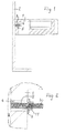
- Figs 1 and 2 illustrate a wash basin 1 or the like mounted to a wall 2, provided with preferably two fixed attachment screws 3 at the same level, The back wall of the wash basin 1 is provided with holes 4, through which the attachment screws 3 can extend.
- a first embodiment of a mounting device for accomplishing a favorable mounting comprises a mounting sleeve 5 and an attachment nut 11.
- the mounting sleeve 5 is shown in Figs 2 and 3 and is preferably made of a strong plastic material with a certain inherent flexibility, for example reinforced polyamide. Its main portion is a tube 6 with larger diameter than the attachment screw 3. At its upper end the tube 6 may be provided with two diametrically opposed wings 7, extending substantially perpendicularly out from the brim of the tube but with a certain inclination down against the tube 6. (Alternatively, for example one, three, four or more such wings can be provided.) The wings 7 constitute a flexible holding means.
- the tube 6 can be provided with for example two longitudinal, flexible tongues 6a with internal thread portions 6b at a somewhat smaller diameter than the attachment screw 3, The threads of these portions 6b correspond with the thread of the attachment screw 3.
- This design allows the mounting sleeve 5 to be pushed onto its attachment screw and remain in the attained position.
- the tube 6 is provided with internal threads and the tongues 6a are dispensed with, so that the mounting sleeve 5 has to be threaded onto its attachment screw 3.
- the mounting sleeve 5 In order to provide the mounting sleeve 5 with a certain longitudinal flexibility for a purpose to be described, it has a longitudinally flexible portion, in the shown case a thread-shaped spiral 8 or helical portion in the end opposite the wings 7.
- the helical portion preferably has the same diameter as the tube 6.
- the longitudinally flexible portion may have another position along the mounting sleeve and another design.
- the tube 6 is preferably externally provided with a longitudinal eccentric portion 10 for a purpose to be described.
- the eccentric portion is preferably placed between the two wings 7or perpendicularly to a line between these. As appears most clearly in Fig 5 , this eccentric portion 10 may be hollow.
- An attachment nut 11 is shown in Figs 6 and 7 . It is internally provided with a hole 12 with a thread corresponding to the thread of each attachment screw 3 and externally with a tool grip 13, preferably in the form of a hexagonal nut portion.
- the attachment nut 11 is normally provided with a fixed washer portion 13', but a separate washer may alternatively be used.
- the attachment nut 11 may be made of metal or plastic.
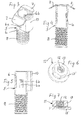
- each attachment screw 3 can be provided with a mounting sleeve 5, as is illustrated in Fig 8a . Due to its construction, the mounting sleeve 5 can be pushed onto the attachment screw 3 but will then remain in its reached position. The mounting sleeve can simply be pushed into contact with the wall 2, but it is alternatively possible to leave a distance from the mounting sleeve to the wall After the mounting of the mounting sleeve 5, its wings 7 are to extend along a vertical line with one wing generally upwards.
- the comparatively large holes 4 in the wash basin 1 are to be matched onto the attachment screws with much smaller diameter, which facilitates the mounting for the person, who does not even see the holes.
- the wash basin 1 Due to the engagement of the mounting sleeve thread portions 6b with the attachment screws 3 and due to the snapped-up wings 7, one of which is extending generally upwards, the wash basin 1 is now securely held on the attachment screws 3 and can be released by the mounting person. When released, the wash basin 1 can attain a somewhat sloping position, as illustrated in Figs 8d and 8e .
- FIG 8f A final stage is shown in Fig 8f .
- the thread-shaped spiral 8 of the mounting sleeve 5 is being compressed for shortening of the mounting sleeve 5: the mounting sleeve 5 is allowed to move on its attachment screw 3 due to the flexible tongues 6a.
- the wings 7 are pressed to a vertical position into full engagement with the wash basin 1.
- attachment screws 3 may be difficult even for a skilled craftsman to mount the two attachment screws 3 at exactly the same height and at the exact desired distance from each other, especially in concrete or brick walls. Also, the attachment screws do not always extend perpendicularly out from the wall. In order to compensate for such deficiencies it is customary to provide the back wall of the wash basin 1 with somewhat oval holes, whose minimal cross-sectional dimension is larger than the diameter of the attachment screw 3. Such oval holes can compensate for deviations in the horizontal sense but not in the vertical sense.
- holes in wash basins shall have the following dimensions: height 20 ⁇ 2 mm and length 30 ⁇ 2 mm.
- the wall thickness at the holes could be 32 ⁇ 3 mm and c/c for the two holes shall be 280 ⁇ 10 mm.
- a height adjustment can be performed by rotating either of or possibly both mounting sleeves 5 to the degree necessary for obtaining the desired height adjustment by means of the eccentric portions 10 in engagement with the wash basin holes.
- the attachment nut 11 is unthreaded. As depicted in Fig 10 , the mounting sleeve 5 can then be rotated to a position where the otherwise stopping wings 7 are within the limits of the oval hole 4. The wash basin can now be freely removed from the attachment screws.
- FIG 11 A second embodiment of a mounting sleeve for a mounting device according to the invention is shown in Fig 11 .
- This mounting sleeve 15 may be made of the same material as the mounting sleeve 5 of the first embodiment and comprises a tube 16 with internal threads 17 for cooperation with an attachment screw 3.
- the tube 16 could be provided with tongue and thread portions, as is shown for the mounting sleeve 5 of Figs 3-5 .
- the mounting sleeve 1 is also provided with a longitudinal eccentric portion 18 with the same design and purpose as the eccentric portion 10 of the mounting sleeve 5.
- the flexible holding means in this embodiment comprises at either side of the end of the tube 16 a guide wing 19 and a holding wing 20.
- the guide wings 19 extend generally perpendicularly out from the tube 16, whereas each holding wing 20 extends generally in the longitudinal direction of the tube 16 from an intermediate part of the guide wing 19.
- the holding wings 20 may preferably, as shown, have curved ends for a reason to be described.
- the eccentric portion 18 is preferably placed between the two holding means 19, 20.
- Fig 12 illustrates in an end view the relative positions of the different parts - corresponding to Fig 13a - when a wash basin 1 is to be pushed onto the attachment screw 3 provided with a mounting sleeve 15 according to the second embodiment. It appears that the hole 4 in the wash basin back wall is clearly oval and that the guiding wings 19 extend outside the hole 4 also in its wider dimension.
- Fig 13 a shows the beginning of the mounting.
- the wash basin 1 has been moved to the left in the drawing so far that the hole 4 in its back wall is partly over the attachment screw 3 previously provided with the mounting sleeve 15. It appears that there are great tolerances in the relative position of the wash basin 1, as the diameter of the attachment screw 3 is small in comparison with the cross dimension of the oval hole 4. It also appears that the guide wings 19 extend outside the longest dimension of the hole 4, whereas the holding wings 20 are inside this dimension. The purpose hereof will appear below.
- Fig 13c shows the situation after further movement when the holding wings 20 are outside the back wall of wash basin 1. Due to the interaction between the guide wings 19 and the walls of the hole 4, the holding wings 20 will be pressed apart and engage the wall outside the hole 4,
- the wash basin 1 is now held by the holding wings 20 on the mounting sleeve 15 in such a way that it can be released by the mounting person.
- the final mounting depicted in Fig 13d can now be performed by tightening an attachment nut 21 of the same type as the attachment nut 11 for the first embodiment.
- the attachment nut 21 will engage the holding wings 20, which again is possible, as there are two wings and symmetry is obtained.
- a third embodiment of a mounting device according to the invention is shown in Figs 14-29 , to which reference now is made.
- a mounting sleeve 30 for this mounting device is shown in Figs 14-16 and is preferably made of a strong plastic material with a certain inherent flexibility. Its main portion is a tube 31 with somewhat larger diameter than an attachment screw 32 (first shown in Fig 25 ), with which it is intended to cooperate.
- the tube 31 is provided with fixed flanges 33, extending perpendicularly out in two opposite directions from the tube 31, and at its other end with somewhat flexible wings 34, extending obliquely out from the tube 31 and together forming a funnel 35 with an oval cross-sectional shape, Integral with wings and extending out under the funnel 35 along the longer dimension of the funnel and in the same direction as the flanges 33 are two triangular ribs 36. The lower edge of each rib 36 is perpendicular to the tube 30.
- the wings 34 forming the funnel 35 may be defined as a flexible holding means.
- the tube 31 is provided with for example two longitudinal, flexible tongues 3 1 a with internal thread portions 31 b at a somewhat smaller diameter than and for engagement with the attachment screw 32. This design allows the mounting sleeve 30 to be pushed onto its attachment screw and remain in the attained position.
- the tube 31 is preferably externally provided with a longitudinal eccentric portion 37 for a purpose to be described.
- the eccentric portion is preferably placed between the two flanges 33 or perpendicularly to a line between these, As appears most clearly in Fig 15 , this eccentric portion 37 may be hollow.
- An attachment nut 38 is shown in Figs 17-19 . It is internally provided with a hole with a thread corresponding to the thread of the attachment screw 32 and externally with a tool grip 39, preferably in the form of a hexagonal nut portion.
- the attachment nut 38 is provided with a hood portion 40 with enough dimensions to cover the flanges 33 of the mounting sleeve 30.
- the attachment nut 38 can be made of plastic or metal, preferably plastic.
- Fig 20 is an illustration from the back side of a wash basin 41, which appears in different cross-sections in all remaining Figs 21-29 , showing different mounting stages.
- Fig 20 shows a mounting stage also shown in Figs 23 and 24 .
- the wash basin 41 is in its back wall provided with preferably two oval holes 42. The left one of these is shown provided with a mounting sleeve 30. The longer dimension of the holes 42 is horizontal and will provide access for the two mounting sleeve flanges 33.
- the back wall is in its shown surface for mounting against a wall provided with notches 43 at the holes 42 with dimensions for providing space for movement therein of the mounting sleeve funnels 35.
- a first mounting stage is illustrated in Figs 21 and 22 .
- a mounting sleeve 30 is inserted or pushed into each wash basin hole 42 from the back side of the wash basin 41 with the flanges 33 first,
- the eccentric portion 37 may be directed downwards.
- Each mounting sleeve 30 is rotated 90o, so that its flanges 33 are supported by the inside of the wash basin back wall and the triangular ribs 36 of the funnel wings 34 are supported by the back wall notch bottom.
- the length of the mounting sleeve tube 31 is such that the funnel 35 is slightly inwardly compressed at this rotation, which means that the mounting sleeve 30 is held in place with a certain force but still can be moved sideways to a certain extent in the oval hole 42.
- the wash basin 41 may now be lifted to the vicinity of attachment screws 32, perpendicularly attached to a vertical wall 44. It will be relatively easy to male a mounting sleeve 30 in the wash basin 41 with its attachment screw 32. Even if the distance between the mounting sleeves 30 in the wash basin 41 is not exactly the same as the distance between the attachment screws 32, the guiding provided by the mounting sleeve tunnels 35 and the possibility to move the wash basin 41 sideways to a certain extent will make it possible to thread the wash basin 41 with its mounting sleeves 30 onto the attachment screws 32, until the back wall of the wash basin 41 comes in contact with the wall 44. Due to the flexibility of the tube tongues 31a (with their internal thread portions 31b) this will be possible.
- the attachment nuts 38 can now - without stress and without any need to concurrently hold the wash basin 41 - be attached to the attachment screws 32.
- Figs 27 and 28 illustrate the normally last mounting stage, namely the tightening of the attachment nuts 38.
- the internal shape of the attachment nuts 38 means that the tightening force is applied not on the mounting sleeves 30 but on the wash basin back wall. This means that the tightening area becomes larger and that the mounting sleeve 30 is not exposed to the tightening force but only has to carry the weight of the wash basin (normally up to 25 kg).
- attachment screws 32 are not placed at exactly the same height or otherwise the wash basin 41 is not horizontal after mounting, adjustment can be made by loosening the nuts 38 and rotating one or both mounting sleeves 30 for engaging its eccentric portion 37 in a new position in relation to the hole 42, so that the height difference is compensated for. This is illustrated in Fig 29 .
- the attachment nuts 38 are first removed, whereafter the mounting sleeves 30 are rotated (normally 10°), so that their flanges 33 and funnels 35 can pass through the oval holes 42. This rotation can for example be made by engaging a screwdriver in the hollow eccentric portion 37. The wash basin is now free to be removed. At a new mounting the same mounting sleeves 30 may be used again.
Landscapes
- Engineering & Computer Science (AREA)
- Health & Medical Sciences (AREA)
- Public Health (AREA)
- Life Sciences & Earth Sciences (AREA)
- Hydrology & Water Resources (AREA)
- Water Supply & Treatment (AREA)
- General Engineering & Computer Science (AREA)
- Mechanical Engineering (AREA)
- Environmental & Geological Engineering (AREA)
- Sink And Installation For Waste Water (AREA)
Applications Claiming Priority (1)
| Application Number | Priority Date | Filing Date | Title |
|---|---|---|---|
| SE1050591A SE534898C2 (sv) | 2010-06-09 | 2010-06-09 | Sätt och anordning för montering av ett tvättställ eller liknande vid en vägg |
Publications (3)
| Publication Number | Publication Date |
|---|---|
| EP2394550A2 true EP2394550A2 (de) | 2011-12-14 |
| EP2394550A3 EP2394550A3 (de) | 2014-05-28 |
| EP2394550B1 EP2394550B1 (de) | 2016-03-23 |
Family
ID=44118121
Family Applications (1)
| Application Number | Title | Priority Date | Filing Date |
|---|---|---|---|
| EP11168400.7A Not-in-force EP2394550B1 (de) | 2010-06-09 | 2011-06-01 | Vorrichtung zur Montage eines Waschbeckens oder dergleichen an eine Wand und Verwendungsverfahren dafür |
Country Status (4)
| Country | Link |
|---|---|
| EP (1) | EP2394550B1 (de) |
| DK (1) | DK2394550T3 (de) |
| PL (1) | PL2394550T3 (de) |
| SE (1) | SE534898C2 (de) |
Cited By (2)
| Publication number | Priority date | Publication date | Assignee | Title |
|---|---|---|---|---|
| CN103690078A (zh) * | 2013-12-18 | 2014-04-02 | 周佩龙 | 一种医用洗漱设备 |
| WO2018065355A1 (de) * | 2016-10-04 | 2018-04-12 | FECHTER, Harald | Anordnung für die installation und wandmontage eines waschbeckens oder dergleichen |
Family Cites Families (2)
| Publication number | Priority date | Publication date | Assignee | Title |
|---|---|---|---|---|
| US2208199A (en) * | 1938-06-08 | 1940-07-16 | Martin A Sisk | Water closet support |
| DE9114083U1 (de) * | 1991-11-05 | 1991-12-19 | Schulte, Helmut, 5880 Lüdenscheid | Bundhülse |
-
2010
- 2010-06-09 SE SE1050591A patent/SE534898C2/sv not_active IP Right Cessation
-
2011
- 2011-06-01 DK DK11168400.7T patent/DK2394550T3/en active
- 2011-06-01 EP EP11168400.7A patent/EP2394550B1/de not_active Not-in-force
- 2011-06-01 PL PL11168400T patent/PL2394550T3/pl unknown
Non-Patent Citations (1)
| Title |
|---|
| None |
Cited By (8)
| Publication number | Priority date | Publication date | Assignee | Title |
|---|---|---|---|---|
| CN103690078A (zh) * | 2013-12-18 | 2014-04-02 | 周佩龙 | 一种医用洗漱设备 |
| WO2018065355A1 (de) * | 2016-10-04 | 2018-04-12 | FECHTER, Harald | Anordnung für die installation und wandmontage eines waschbeckens oder dergleichen |
| AT519178A1 (de) * | 2016-10-04 | 2018-04-15 | Andre Rathammer | Anordnung für die Installation und Wandmontage eines Waschbeckens oder dergleichen |
| AT519178B1 (de) * | 2016-10-04 | 2018-08-15 | Andre Rathammer | Anordnung für die Installation und Wandmontage eines Waschbeckens oder dergleichen |
| CN109790705A (zh) * | 2016-10-04 | 2019-05-21 | 安德烈·拉特哈默尔 | 用于盥洗盆或类似物的装配以及壁式安装的装置 |
| JP2019534405A (ja) * | 2016-10-04 | 2019-11-28 | ラートハマー、アンドレ | 洗面台等の設置及び壁取付けのための構成 |
| US11168469B2 (en) | 2016-10-04 | 2021-11-09 | Andre Rathammer | Arrangement for the installation and wall mounting of a wash basin or the like |
| AU2017338259B2 (en) * | 2016-10-04 | 2022-06-02 | FECHTER, Harald | Arrangement for the installation and wall mounting of a wash basin or the like |
Also Published As
| Publication number | Publication date |
|---|---|
| SE534898C2 (sv) | 2012-02-07 |
| PL2394550T3 (pl) | 2017-01-31 |
| DK2394550T3 (en) | 2016-07-04 |
| EP2394550B1 (de) | 2016-03-23 |
| EP2394550A3 (de) | 2014-05-28 |
| SE1050591A1 (sv) | 2011-12-10 |
Similar Documents
| Publication | Publication Date | Title |
|---|---|---|
| US8245988B2 (en) | Bath fixture mounting method | |
| US20120110729A1 (en) | Bath curtain rod assemblies | |
| JP3987579B2 (ja) | インプラントシステム用の装置 | |
| US5864898A (en) | Apron assembly for a bathing fixture | |
| US20080296460A1 (en) | Ceiling mounted brace for an electrical fixture | |
| KR200439136Y1 (ko) | 거푸집용 체결 버팀대 | |
| EP2394550B1 (de) | Vorrichtung zur Montage eines Waschbeckens oder dergleichen an eine Wand und Verwendungsverfahren dafür | |
| US20020171013A1 (en) | Pipe clamp arrangement | |
| CN115003891B (zh) | 用于设置和安装盥洗盆的装置 | |
| EA023026B1 (ru) | Система установки бака для воды | |
| KR100941154B1 (ko) | 건축용 인서트 및 이를 이용한 배관 지지장치 | |
| US20100314519A1 (en) | Universal Support | |
| US9181709B2 (en) | Rapidly mounted, modular, universal grab bar and handrail system | |
| KR101625368B1 (ko) | 설치 호환성을 구비한 수전함 어셈블리 | |
| US20060123539A1 (en) | System and method for attaching a drain assembly to a plumbing fixture | |
| AU2013203844A1 (en) | Clamping device for mounting a faucet head | |
| US20240060284A1 (en) | Wall mount | |
| JPH09507541A (ja) | 外側固定部分と内側交換可能部分の2つの部分に分離されたビルディングの汚水用排水システム | |
| DK2615943T3 (en) | SEPARATORY DEVICE AND PROCEDURE | |
| US20060182511A1 (en) | Mounting device | |
| JP3146004U (ja) | 複合ねじ | |
| JPH0941436A (ja) | 配管用ボックス装置 | |
| KR200334320Y1 (ko) | 벽면부착형 샤워기용 물공급관 고정구 | |
| GB2117859A (en) | Expanding fasteners for bath handles | |
| KR200242495Y1 (ko) | 풀림 방지용 밀침장치 |
Legal Events
| Date | Code | Title | Description |
|---|---|---|---|
| AK | Designated contracting states |
Kind code of ref document: A2 Designated state(s): AL AT BE BG CH CY CZ DE DK EE ES FI FR GB GR HR HU IE IS IT LI LT LU LV MC MK MT NL NO PL PT RO RS SE SI SK SM TR |
|
| AX | Request for extension of the european patent |
Extension state: BA ME |
|
| PUAI | Public reference made under article 153(3) epc to a published international application that has entered the european phase |
Free format text: ORIGINAL CODE: 0009012 |
|
| PUAL | Search report despatched |
Free format text: ORIGINAL CODE: 0009013 |
|
| AK | Designated contracting states |
Kind code of ref document: A3 Designated state(s): AL AT BE BG CH CY CZ DE DK EE ES FI FR GB GR HR HU IE IS IT LI LT LU LV MC MK MT NL NO PL PT RO RS SE SI SK SM TR |
|
| AX | Request for extension of the european patent |
Extension state: BA ME |
|
| RIC1 | Information provided on ipc code assigned before grant |
Ipc: A47K 1/05 20060101AFI20140424BHEP |
|
| 17P | Request for examination filed |
Effective date: 20141127 |
|
| RBV | Designated contracting states (corrected) |
Designated state(s): AL AT BE BG CH CY CZ DE DK EE ES FI FR GB GR HR HU IE IS IT LI LT LU LV MC MK MT NL NO PL PT RO RS SE SI SK SM TR |
|
| GRAP | Despatch of communication of intention to grant a patent |
Free format text: ORIGINAL CODE: EPIDOSNIGR1 |
|
| INTG | Intention to grant announced |
Effective date: 20150916 |
|
| GRAS | Grant fee paid |
Free format text: ORIGINAL CODE: EPIDOSNIGR3 |
|
| GRAA | (expected) grant |
Free format text: ORIGINAL CODE: 0009210 |
|
| AK | Designated contracting states |
Kind code of ref document: B1 Designated state(s): AL AT BE BG CH CY CZ DE DK EE ES FI FR GB GR HR HU IE IS IT LI LT LU LV MC MK MT NL NO PL PT RO RS SE SI SK SM TR |
|
| REG | Reference to a national code |
Ref country code: GB Ref legal event code: FG4D |
|
| REG | Reference to a national code |
Ref country code: CH Ref legal event code: EP |
|
| REG | Reference to a national code |
Ref country code: AT Ref legal event code: REF Ref document number: 782269 Country of ref document: AT Kind code of ref document: T Effective date: 20160415 |
|
| REG | Reference to a national code |
Ref country code: IE Ref legal event code: FG4D |
|
| REG | Reference to a national code |
Ref country code: DE Ref legal event code: R096 Ref document number: 602011024245 Country of ref document: DE |
|
| REG | Reference to a national code |
Ref country code: DK Ref legal event code: T3 Effective date: 20160624 |
|
| REG | Reference to a national code |
Ref country code: FR Ref legal event code: PLFP Year of fee payment: 6 |
|
| REG | Reference to a national code |
Ref country code: SE Ref legal event code: TRGR |
|
| RAP2 | Party data changed (patent owner data changed or rights of a patent transferred) |
Owner name: GEBERIT SERVICE AB |
|
| REG | Reference to a national code |
Ref country code: NL Ref legal event code: FP |
|
| REG | Reference to a national code |
Ref country code: CH Ref legal event code: PUE Owner name: GEBERIT SERVICE AB, SE Free format text: FORMER OWNER: IFOE SANITAER AB, SE |
|
| REG | Reference to a national code |
Ref country code: LT Ref legal event code: MG4D |
|
| PG25 | Lapsed in a contracting state [announced via postgrant information from national office to epo] |
Ref country code: GR Free format text: LAPSE BECAUSE OF FAILURE TO SUBMIT A TRANSLATION OF THE DESCRIPTION OR TO PAY THE FEE WITHIN THE PRESCRIBED TIME-LIMIT Effective date: 20160624 Ref country code: HR Free format text: LAPSE BECAUSE OF FAILURE TO SUBMIT A TRANSLATION OF THE DESCRIPTION OR TO PAY THE FEE WITHIN THE PRESCRIBED TIME-LIMIT Effective date: 20160323 |
|
| REG | Reference to a national code |
Ref country code: NO Ref legal event code: T2 Effective date: 20160323 |
|
| PG25 | Lapsed in a contracting state [announced via postgrant information from national office to epo] |
Ref country code: LV Free format text: LAPSE BECAUSE OF FAILURE TO SUBMIT A TRANSLATION OF THE DESCRIPTION OR TO PAY THE FEE WITHIN THE PRESCRIBED TIME-LIMIT Effective date: 20160323 Ref country code: RS Free format text: LAPSE BECAUSE OF FAILURE TO SUBMIT A TRANSLATION OF THE DESCRIPTION OR TO PAY THE FEE WITHIN THE PRESCRIBED TIME-LIMIT Effective date: 20160323 Ref country code: LT Free format text: LAPSE BECAUSE OF FAILURE TO SUBMIT A TRANSLATION OF THE DESCRIPTION OR TO PAY THE FEE WITHIN THE PRESCRIBED TIME-LIMIT Effective date: 20160323 |
|
| REG | Reference to a national code |
Ref country code: NL Ref legal event code: PD Owner name: GEBERIT SERVICE AB; SE Free format text: DETAILS ASSIGNMENT: VERANDERING VAN EIGENAAR(S), OVERDRACHT; FORMER OWNER NAME: IFOE SANITAER AB Effective date: 20160621 |
|
| REG | Reference to a national code |
Ref country code: GB Ref legal event code: 732E Free format text: REGISTERED BETWEEN 20160901 AND 20160907 |
|
| PG25 | Lapsed in a contracting state [announced via postgrant information from national office to epo] |
Ref country code: EE Free format text: LAPSE BECAUSE OF FAILURE TO SUBMIT A TRANSLATION OF THE DESCRIPTION OR TO PAY THE FEE WITHIN THE PRESCRIBED TIME-LIMIT Effective date: 20160323 Ref country code: IS Free format text: LAPSE BECAUSE OF FAILURE TO SUBMIT A TRANSLATION OF THE DESCRIPTION OR TO PAY THE FEE WITHIN THE PRESCRIBED TIME-LIMIT Effective date: 20160723 |
|
| PG25 | Lapsed in a contracting state [announced via postgrant information from national office to epo] |
Ref country code: SM Free format text: LAPSE BECAUSE OF FAILURE TO SUBMIT A TRANSLATION OF THE DESCRIPTION OR TO PAY THE FEE WITHIN THE PRESCRIBED TIME-LIMIT Effective date: 20160323 Ref country code: RO Free format text: LAPSE BECAUSE OF FAILURE TO SUBMIT A TRANSLATION OF THE DESCRIPTION OR TO PAY THE FEE WITHIN THE PRESCRIBED TIME-LIMIT Effective date: 20160323 Ref country code: ES Free format text: LAPSE BECAUSE OF FAILURE TO SUBMIT A TRANSLATION OF THE DESCRIPTION OR TO PAY THE FEE WITHIN THE PRESCRIBED TIME-LIMIT Effective date: 20160323 Ref country code: SK Free format text: LAPSE BECAUSE OF FAILURE TO SUBMIT A TRANSLATION OF THE DESCRIPTION OR TO PAY THE FEE WITHIN THE PRESCRIBED TIME-LIMIT Effective date: 20160323 Ref country code: PT Free format text: LAPSE BECAUSE OF FAILURE TO SUBMIT A TRANSLATION OF THE DESCRIPTION OR TO PAY THE FEE WITHIN THE PRESCRIBED TIME-LIMIT Effective date: 20160725 |
|
| REG | Reference to a national code |
Ref country code: DE Ref legal event code: R097 Ref document number: 602011024245 Country of ref document: DE |
|
| PLBE | No opposition filed within time limit |
Free format text: ORIGINAL CODE: 0009261 |
|
| STAA | Information on the status of an ep patent application or granted ep patent |
Free format text: STATUS: NO OPPOSITION FILED WITHIN TIME LIMIT |
|
| PG25 | Lapsed in a contracting state [announced via postgrant information from national office to epo] |
Ref country code: MC Free format text: LAPSE BECAUSE OF FAILURE TO SUBMIT A TRANSLATION OF THE DESCRIPTION OR TO PAY THE FEE WITHIN THE PRESCRIBED TIME-LIMIT Effective date: 20160323 |
|
| PG25 | Lapsed in a contracting state [announced via postgrant information from national office to epo] |
Ref country code: BG Free format text: LAPSE BECAUSE OF FAILURE TO SUBMIT A TRANSLATION OF THE DESCRIPTION OR TO PAY THE FEE WITHIN THE PRESCRIBED TIME-LIMIT Effective date: 20160623 |
|
| 26N | No opposition filed |
Effective date: 20170102 |
|
| REG | Reference to a national code |
Ref country code: DE Ref legal event code: R081 Ref document number: 602011024245 Country of ref document: DE Owner name: GEBERIT SERVICE AB, SE Free format text: FORMER OWNER: IFOE SANITAER AB, BROMOELLA, SE |
|
| REG | Reference to a national code |
Ref country code: IE Ref legal event code: MM4A |
|
| PG25 | Lapsed in a contracting state [announced via postgrant information from national office to epo] |
Ref country code: IE Free format text: LAPSE BECAUSE OF NON-PAYMENT OF DUE FEES Effective date: 20160601 Ref country code: SI Free format text: LAPSE BECAUSE OF FAILURE TO SUBMIT A TRANSLATION OF THE DESCRIPTION OR TO PAY THE FEE WITHIN THE PRESCRIBED TIME-LIMIT Effective date: 20160323 |
|
| REG | Reference to a national code |
Ref country code: FR Ref legal event code: PLFP Year of fee payment: 7 |
|
| REG | Reference to a national code |
Ref country code: AT Ref legal event code: PC Ref document number: 782269 Country of ref document: AT Kind code of ref document: T Owner name: GEBERIT SERVICE AB, SE Effective date: 20171120 |
|
| PG25 | Lapsed in a contracting state [announced via postgrant information from national office to epo] |
Ref country code: CY Free format text: LAPSE BECAUSE OF FAILURE TO SUBMIT A TRANSLATION OF THE DESCRIPTION OR TO PAY THE FEE WITHIN THE PRESCRIBED TIME-LIMIT Effective date: 20160323 Ref country code: HU Free format text: LAPSE BECAUSE OF FAILURE TO SUBMIT A TRANSLATION OF THE DESCRIPTION OR TO PAY THE FEE WITHIN THE PRESCRIBED TIME-LIMIT; INVALID AB INITIO Effective date: 20110601 |
|
| REG | Reference to a national code |
Ref country code: FR Ref legal event code: PLFP Year of fee payment: 8 |
|
| PG25 | Lapsed in a contracting state [announced via postgrant information from national office to epo] |
Ref country code: MT Free format text: LAPSE BECAUSE OF NON-PAYMENT OF DUE FEES Effective date: 20160630 Ref country code: TR Free format text: LAPSE BECAUSE OF FAILURE TO SUBMIT A TRANSLATION OF THE DESCRIPTION OR TO PAY THE FEE WITHIN THE PRESCRIBED TIME-LIMIT Effective date: 20160323 Ref country code: LU Free format text: LAPSE BECAUSE OF NON-PAYMENT OF DUE FEES Effective date: 20160601 Ref country code: MK Free format text: LAPSE BECAUSE OF FAILURE TO SUBMIT A TRANSLATION OF THE DESCRIPTION OR TO PAY THE FEE WITHIN THE PRESCRIBED TIME-LIMIT Effective date: 20160323 |
|
| PG25 | Lapsed in a contracting state [announced via postgrant information from national office to epo] |
Ref country code: AL Free format text: LAPSE BECAUSE OF FAILURE TO SUBMIT A TRANSLATION OF THE DESCRIPTION OR TO PAY THE FEE WITHIN THE PRESCRIBED TIME-LIMIT Effective date: 20160323 |
|
| REG | Reference to a national code |
Ref country code: AT Ref legal event code: UEP Ref document number: 782269 Country of ref document: AT Kind code of ref document: T Effective date: 20160323 |
|
| PGFP | Annual fee paid to national office [announced via postgrant information from national office to epo] |
Ref country code: DE Payment date: 20210609 Year of fee payment: 11 Ref country code: CZ Payment date: 20210524 Year of fee payment: 11 Ref country code: FR Payment date: 20210608 Year of fee payment: 11 Ref country code: FI Payment date: 20210603 Year of fee payment: 11 Ref country code: NL Payment date: 20210608 Year of fee payment: 11 Ref country code: IT Payment date: 20210607 Year of fee payment: 11 Ref country code: NO Payment date: 20210622 Year of fee payment: 11 |
|
| PGFP | Annual fee paid to national office [announced via postgrant information from national office to epo] |
Ref country code: PL Payment date: 20210528 Year of fee payment: 11 Ref country code: SE Payment date: 20210608 Year of fee payment: 11 Ref country code: AT Payment date: 20210604 Year of fee payment: 11 Ref country code: BE Payment date: 20210608 Year of fee payment: 11 Ref country code: DK Payment date: 20210608 Year of fee payment: 11 Ref country code: CH Payment date: 20210611 Year of fee payment: 11 Ref country code: GB Payment date: 20210608 Year of fee payment: 11 |
|
| REG | Reference to a national code |
Ref country code: DE Ref legal event code: R119 Ref document number: 602011024245 Country of ref document: DE |
|
| REG | Reference to a national code |
Ref country code: FI Ref legal event code: MAE |
|
| REG | Reference to a national code |
Ref country code: NO Ref legal event code: MMEP Ref country code: DK Ref legal event code: EBP Effective date: 20220630 |
|
| PG25 | Lapsed in a contracting state [announced via postgrant information from national office to epo] |
Ref country code: FI Free format text: LAPSE BECAUSE OF NON-PAYMENT OF DUE FEES Effective date: 20220601 Ref country code: CZ Free format text: LAPSE BECAUSE OF NON-PAYMENT OF DUE FEES Effective date: 20220601 |
|
| REG | Reference to a national code |
Ref country code: CH Ref legal event code: PL Ref country code: SE Ref legal event code: EUG |
|
| REG | Reference to a national code |
Ref country code: NL Ref legal event code: MM Effective date: 20220701 |
|
| REG | Reference to a national code |
Ref country code: AT Ref legal event code: MM01 Ref document number: 782269 Country of ref document: AT Kind code of ref document: T Effective date: 20220601 |
|
| REG | Reference to a national code |
Ref country code: BE Ref legal event code: MM Effective date: 20220630 |
|
| GBPC | Gb: european patent ceased through non-payment of renewal fee |
Effective date: 20220601 |
|
| PG25 | Lapsed in a contracting state [announced via postgrant information from national office to epo] |
Ref country code: NL Free format text: LAPSE BECAUSE OF NON-PAYMENT OF DUE FEES Effective date: 20220701 |
|
| PG25 | Lapsed in a contracting state [announced via postgrant information from national office to epo] |
Ref country code: SE Free format text: LAPSE BECAUSE OF NON-PAYMENT OF DUE FEES Effective date: 20220602 Ref country code: NO Free format text: LAPSE BECAUSE OF NON-PAYMENT OF DUE FEES Effective date: 20220630 Ref country code: LI Free format text: LAPSE BECAUSE OF NON-PAYMENT OF DUE FEES Effective date: 20220630 Ref country code: FR Free format text: LAPSE BECAUSE OF NON-PAYMENT OF DUE FEES Effective date: 20220630 Ref country code: CH Free format text: LAPSE BECAUSE OF NON-PAYMENT OF DUE FEES Effective date: 20220630 Ref country code: AT Free format text: LAPSE BECAUSE OF NON-PAYMENT OF DUE FEES Effective date: 20220601 |
|
| PG25 | Lapsed in a contracting state [announced via postgrant information from national office to epo] |
Ref country code: GB Free format text: LAPSE BECAUSE OF NON-PAYMENT OF DUE FEES Effective date: 20220601 Ref country code: DE Free format text: LAPSE BECAUSE OF NON-PAYMENT OF DUE FEES Effective date: 20230103 Ref country code: BE Free format text: LAPSE BECAUSE OF NON-PAYMENT OF DUE FEES Effective date: 20220630 |
|
| PG25 | Lapsed in a contracting state [announced via postgrant information from national office to epo] |
Ref country code: IT Free format text: LAPSE BECAUSE OF NON-PAYMENT OF DUE FEES Effective date: 20220601 Ref country code: DK Free format text: LAPSE BECAUSE OF NON-PAYMENT OF DUE FEES Effective date: 20220630 |
|
| PG25 | Lapsed in a contracting state [announced via postgrant information from national office to epo] |
Ref country code: PL Free format text: LAPSE BECAUSE OF NON-PAYMENT OF DUE FEES Effective date: 20220601 |