EP2395175A2 - Klammeranordnung für eine stehende Schweißnaht - Google Patents
Klammeranordnung für eine stehende Schweißnaht Download PDFInfo
- Publication number
- EP2395175A2 EP2395175A2 EP11168562A EP11168562A EP2395175A2 EP 2395175 A2 EP2395175 A2 EP 2395175A2 EP 11168562 A EP11168562 A EP 11168562A EP 11168562 A EP11168562 A EP 11168562A EP 2395175 A2 EP2395175 A2 EP 2395175A2
- Authority
- EP
- European Patent Office
- Prior art keywords
- arms
- clamp assembly
- protrusions
- body member
- standing seam
- Prior art date
- Legal status (The legal status is an assumption and is not a legal conclusion. Google has not performed a legal analysis and makes no representation as to the accuracy of the status listed.)
- Withdrawn
Links
- 230000000295 complement effect Effects 0.000 claims abstract description 7
- 229910052751 metal Inorganic materials 0.000 claims abstract description 7
- 239000002184 metal Substances 0.000 claims abstract description 7
- 239000011324 bead Substances 0.000 claims description 5
- 210000003414 extremity Anatomy 0.000 description 14
- 230000000694 effects Effects 0.000 description 5
- 230000007423 decrease Effects 0.000 description 2
- 239000004411 aluminium Substances 0.000 description 1
- 229910052782 aluminium Inorganic materials 0.000 description 1
- XAGFODPZIPBFFR-UHFFFAOYSA-N aluminium Chemical compound [Al] XAGFODPZIPBFFR-UHFFFAOYSA-N 0.000 description 1
- 238000005452 bending Methods 0.000 description 1
- 230000001788 irregular Effects 0.000 description 1
- 230000014759 maintenance of location Effects 0.000 description 1
- 229910001092 metal group alloy Inorganic materials 0.000 description 1
- 230000035515 penetration Effects 0.000 description 1
- 230000000717 retained effect Effects 0.000 description 1
- 238000007788 roughening Methods 0.000 description 1
- 238000001881 scanning electron acoustic microscopy Methods 0.000 description 1
- 210000001364 upper extremity Anatomy 0.000 description 1
Images




Classifications
-
- E—FIXED CONSTRUCTIONS
- E04—BUILDING
- E04G—SCAFFOLDING; FORMS; SHUTTERING; BUILDING IMPLEMENTS OR AIDS, OR THEIR USE; HANDLING BUILDING MATERIALS ON THE SITE; REPAIRING, BREAKING-UP OR OTHER WORK ON EXISTING BUILDINGS
- E04G21/00—Preparing, conveying, or working-up building materials or building elements in situ; Other devices or measures for constructional work
- E04G21/32—Safety or protective measures for persons during the construction of buildings
- E04G21/3261—Safety-nets; Safety mattresses; Arrangements on buildings for connecting safety-lines
-
- E—FIXED CONSTRUCTIONS
- E04—BUILDING
- E04G—SCAFFOLDING; FORMS; SHUTTERING; BUILDING IMPLEMENTS OR AIDS, OR THEIR USE; HANDLING BUILDING MATERIALS ON THE SITE; REPAIRING, BREAKING-UP OR OTHER WORK ON EXISTING BUILDINGS
- E04G21/00—Preparing, conveying, or working-up building materials or building elements in situ; Other devices or measures for constructional work
- E04G21/32—Safety or protective measures for persons during the construction of buildings
- E04G21/3261—Safety-nets; Safety mattresses; Arrangements on buildings for connecting safety-lines
- E04G21/3276—Arrangements on buildings for connecting safety-lines
- E04G21/328—Arrangements on buildings for connecting safety-lines fastened to the roof covering or insulation
- E04G21/3285—Arrangements on buildings for connecting safety-lines fastened to the roof covering or insulation fastened to standing seams of the roof covering
Definitions
- This invention relates to a clamp assembly for a standing seam.
- Standing seams are well known for interconnecting metal panels which are particularly employed for covering roofs of various types of buildings.
- Typical standing seams comprise a protruding (e.g., upstanding) web portion formed by profiling adjacent edges of panels being interconnected and a correspondingly profiled head portion provided at an outer extremity of the web portion and adapted to effect interlocking of the adjacent panels.
- head portion may be of substantially cylindrical, or other, shape.
- a clamp assembly for securing an ancillary device to a standing seam interconnecting metal panels, the standing seam comprising a protruding (for example, upstanding) web portion with a head portion at an outer (for example, upper) extremity thereof
- the clamp assembly comprising: a body member; first and second arms extending from the body member, at least one of the arms being pivotally interconnected with the body member at at least one hinge means, the first and second arms having free end regions; a spreader member formed with an aperture and with first and second protrusions on one face thereof; and threaded fastener means passing through the aperture in the spreader member and engaging in a complementary threaded aperture in the body member, the arrangement being such that, as the threaded fastener means is tightened so as to move the spreader member towards the body member, the first and second protrusions engage with an inner surface of a first end region of each of the arms so as to urge the first end regions apart and to urge a second end regions together to clamp
- Both the first and second arms may be pivotally connected with the body member by way of hinge means.
- the spreader member may extend laterally beyond the first and second protrusions for engagement with the first end region of each of the first and second arms.
- a surface of the body member may be configured to engage with a surface of the spreader member between the first and second protrusions.
- the first and second protrusions may each be formed with an inclined surface for urging the first end regions of the first and second arms apart as the spreader member is moved towards the body member.
- Interengaging means such as a bead and a corresponding recess, may be provided on the first and second protrusions and on the first end regions of the first and second arms and adapted to engage when the clamp assembly is mounted on a protruding web of a standing seam.
- the spreader member may have a substantially planar surface on that side thereof remote from the body member.
- the spreader member may have a substantially planar surface between the first and second protrusions. Alternatively or additionally, the spreader member may have a substantially planar surface on each lateral side thereof relative to the first and second protrusions.
- the aperture in the spreader member may be formed between the first and second protrusions.
- Figure 1 is a perspective view of part of a standing seam roof
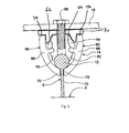
- Figure 2 is an exploded cross-sectional view of one embodiment of a clamp assembly according to the present invention, and an ancillary device, prior to fixing to a standing seam of the roof of Figure 1 ;
- Figure 3 is a cross-sectional view of the clamp assembly and ancillary device of Figure 2 , after fixing to the standing seam of the roof of Figure 1 ;
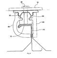
- Figure 4 is a cross-sectional view of another embodiment of a clamp assembly according to the present invention.
- Figure 5 is a cross-sectional view of a further embodiment of a clamp assembly according to the present invention.
- Figure 6 is a cross-sectional view of another embodiment of a clamp assembly according to the present invention.
- a standing seam roof 2 of a building comprises metal sheets 4, 6 interconnected by a standing seam 8.
- the standing seam 8 is formed by appropriately bending and profiling adjacent edges of the metal sheets 4, 6 and comprises an upstanding web portion 10 with a head portion 12 at an upper extremity thereof, interlocking the profiled edges of the sheets 4, 6 in known manner.
- a clamp assembly 14 for securing an ancillary device 16 to the standing seam 8 of a standing seam roof 2.
- the ancillary device may, for example, comprise or form part of a fall arrest system, a walkway, an aerial or a post.
- the clamp assembly 14 comprises a substantially rigid member 54 adapted to overlie and contact the head portion 12 of the standing seam 8.
- the member 54 is internally contoured, at least in part, at a lower end 56 thereof to substantially conform to the contour of the head portion 12 of the standing seam 8, which in the particular embodiment shown is substantially cylindrical.
- First and second substantially rigid arms 58, 60 of complementary arcuate form are pivotally interconnected, by respective hinge means 62, 64, with opposite sides of the member 54, at intermediate locations 66, 68 on the arms 58, 60.
- the first and second arms 58, 60 extend downwardly from the intermediate locations 66, 68 respectively and curve such that they converge towards one another and are adapted to embrace the head portion 12 of the standing seam 8, in cooperation with the member 54.
- the first and second arms 58, 60 have first and second lower free extremities 70, 72 adapted to face one another and to contact opposite sides of the web portion 10 of the standing seam 8, when the clamp assembly 14 is fitted thereto as best shown in Figure 3 .
- the first and second arms 58, 60 also extend upwardly from the intermediate locations 66, 68 respectively and may curve to an extent such that they converge towards one another.
- the first and second arms 58, 60 are arranged with third and fourth upper free extremities 74, 76 respectively.
- the distance between the first and second free extremities 70, 72 of the first and second arms 58, 60 respectively and the respective intermediate locations 66, 68 may be greater than the distance between the third and fourth free extremities 74, 76 and the respective intermediate locations 66, 68. That is, the lower arms may be longer than the upper arms.
- the member 54 is suitably provided with outwardly-directed curved or angled opposite side edges 78, 80, pivotally receiving the first and second arms 58, 60.
- the member 54 may be of generally hexagonal cross-sectional form, which may be an irregular hexagonal form.
- the hinge means 62, 64 each suitably comprises a groove 82, for example of cylindrical or substantially cylindrical form, provided at the respective opposite side edges 78, 80 of the member 54, and into which is axially slid a complementary protrusion 84, for example of cylindrical or substantially cylindrical form, extending from a respective first and second arm 58, 60 at its respective intermediate location 66, 68.
- a complementary protrusion 84 for example of cylindrical or substantially cylindrical form, extending from a respective first and second arm 58, 60 at its respective intermediate location 66, 68.
- Each of the grooves 82 has a wall thereof subtending an angle of more than 180 degrees, whereby retention of each protrusion 84 in its groove 82 is ensured.
- the grooves 82 may be provided in the arms 58, 60 and the protrusions 84 may be provided at the respective opposite side edges 78, 80 of the member 54.
- the first and second arms 58, 60 and the member 54 are suitably made from a metal or metal alloy, such as aluminium and are suitably provided as extruded forms, including the grooves 82 and the protrusions 84.
- the protrusions 84 may be retained in their axial direction within the grooves 82 by deforming, for example spreading, opposing end portions of the protrusions which extend beyond the axial ends of the grooves.
- a threaded fastener 86 such as a screw or bolt, is arranged to pass through aperture 42 in the ancillary device 16 and into a complementary threaded aperture 88 in the member 54.
- a spreader member 20 forms part of the clamp assembly and is positioned between the ancillary device 16 and the remainder of the clamp assembly 14.
- the spreader member 20 is formed with a plate-like portion having a substantially planar upper surface for receiving a lower surface of the ancillary device 16 and with an aperture 22, for example in a central region thereof.
- the lower surface of the plate-like portion of the spreader member is formed with two protrusions 24, 26, which protrusions each have laterally outer inclined surfaces such that, as the spreader member 20 is moved towards the member 54, the upper ends 74, 76 of the first and second arms 58, 60 are urged apart.
- the inner surfaces of the protrusions 24, 26 are configured so as not to interfere with the member 54 and arms 58, 60 and in the illustrated embodiment are also suitably inclined. That is, the inclined surfaces are such that the distance between the inclined surfaces decreases as the distance from the ancillary device receiving (plate-like) portion increases. As illustrated the inclined surfaces are planar and inclined at an angle of substantially 95 degrees to the lower surface of the ancillary device receiving portion, but they may take any convenient form. That is, the angle of inclination may be modified, for example to 100 degrees, or a plurality of portions inclined at different angles may be provided, or the inclined surfaces may be curved.
- the precise configuration is not important provided the distance between the surfaces decreases as the distance from the underside of the ancillary device receiving portion increases so as to urge the upper ends of the first and second arms apart.
- the surfaces depending from the underside of the ancillary device receiving portion may be substantially perpendicular to the said underside, but the inwardly facing surfaces of the upper regions of the first and second arms may be configured such that, as the protrusions 22, 24 are moved towards the member 54, the upper ends of the arms are urged apart.
- the two protrusions 24, 26 are spaced either side of the aperture 22, while the spreader member projects laterally beyond each protrusion.
- the lower surface of the spreader member may be substantially planar except for the two protrusions, that is, between the protrusions and/or on each side of the protrusions.
- the member 54 has an upper surface 90 which, in association with the third and fourth upper free extremities 74, 76 of the first and second arms 58, 60, is adapted to receive the spreader member 20 when the threaded fastener is tightened, while the ancillary device 16 is supported on an upper surface of the spreader member.
- the threaded fastener passes freely through the aperture 22 formed in the spreader member.
- the first and second arms 58, 60 are pivotable by means of their hinge means 62, 64 into a position whereby the first and second free extremities 70, 72 are separated to permit the clamp assembly 14 to be located on the standing seam 8.
- the third and fourth free extremities 74, 76 extend angularly by a distance d above a plane 92 of the upper surface 90 of the member 54.
- the first and second arms 58, 60 are caused to be pivoted by pressure contact of the spreader member 20 on the third and fourth free extremities 74, 76 of the arms 58, 60 and by pressure contact between the protrusions 24, 26 and the inner surfaces of the arms 58, 60.
- the third and fourth free extremities 74, 76 of the arms 58, 60 are urged outwardly and downwardly into coplanar relationship with the upper surface 90 of the member 54 in which the spreader member 20 bears against the upper surface 90 and against the free extremities of the arms 58, 60 and the first and second free extremities 70, 72 of the arms 58, 60 are urged towards each other and into secure jaw-like gripping engagement with the web portion 10 of the standing seam 8.
- the resulting finished assembly is shown in Figure 5 .
- the effect of the spreader member 20 is to increase the clamping force of the arms 58, 60 on the web portion 10 of the standing seam 8 and to maintain the clamping force in the unlikely event the threaded fastener should become loose.
- the laterally outer surfaces of the protrusions 24, 26 and the internal surfaces of the upper regions of the arms 58, 60 may be formed with interlocking means, such as an axially extending bead on the protrusions and an axially extending recess on the arms such that the spreader member locks with the arms when the spreader member is urged towards the member 54 by the threaded fastener.
- interlocking means such as an axially extending bead on the protrusions and an axially extending recess on the arms such that the spreader member locks with the arms when the spreader member is urged towards the member 54 by the threaded fastener.
- interlocking means such as an axially extending bead on the protrusions and an axially extending recess on the arms such that the spreader member locks with the arms when the spreader member is urged towards the member 54 by the threaded fastener.
- Such an arrangement prevents the spreader member subsequently moving relative to the arms even if the
- the first 70 and/or the second 72 free extremities of the first 58 and/or the second 60 arms may be profiled 94 to enhance grip thereof with the web portion 10 of the standing seam 8, such as by providing serrations thereon or by surface roughening thereof.
- the two hinge means 62, 64 are arranged to have pivotal axes thereof substantially parallel to one another and to a length direction 52 ( Figure 1 ) of the standing seam 8.
- the clamp assembly 14 may be provided of a length selected according to a required application.
- the member 54, with the arms 58, 60 is first positioned over the standing seam with the surface 56 bearing against an upper surface of the seam.
- the spreader member 20 is positioned on the member 54 with the protrusions 24, 26 between the upper ends of the arms 58, 60.
- the ancillary device 16 is then positioned on the spreader member and the threaded fastener 86 is passed through the ancillary device and the spreader member and threaded into the threaded aperture 88 formed in the member 54 and tightened to cause the protrusions to urge the upper ends of the arms 58, 60 apart as the threaded fastener is tightened.
- the clamp assembly shown in Figure 4 is a modified version of the clamp assembly of Figures 2 and 3 and is adapted to a particular form of standing seam.
- the clamp assembly of Figure 4 is provided with one arm which is substantially straight, while the other arm is substantially L-shaped.
- the protrusions 24, 26 of the spreader member 22 are formed with axially extending beads which, in the mounted position of the clamp assembly, engage in axially extending recesses formed in the inner surfaces of the upper ends of the arms 58, 60.
- the clamp assembly shown in Figure 5 is also a modified version of the clamp assembly of Figures 2 and 3 and is adapted to a further particular form of standing seam.
- the clamp assembly of Figure 5 is provided with two arms which are substantially L-shaped, however the arms are of different dimensions so as to be spaced different distances from a slightly off-centre seam.
- the clamp assembly shown in Figure 6 is another modified version of the clamp assembly of Figures 2 and 3 and is adapted to a further particular form of standing seam.
- the clamp assembly of Figure 6 is provided with two arms which are substantially L-shaped, the two arms being of complementary form.
Landscapes
- Engineering & Computer Science (AREA)
- Architecture (AREA)
- Mechanical Engineering (AREA)
- Civil Engineering (AREA)
- Structural Engineering (AREA)
- Clamps And Clips (AREA)
Applications Claiming Priority (1)
| Application Number | Priority Date | Filing Date | Title |
|---|---|---|---|
| GBGB1009692.3A GB201009692D0 (en) | 2010-06-10 | 2010-06-10 | Clamp assembly for a standing seam |
Publications (2)
| Publication Number | Publication Date |
|---|---|
| EP2395175A2 true EP2395175A2 (de) | 2011-12-14 |
| EP2395175A3 EP2395175A3 (de) | 2014-10-22 |
Family
ID=42471422
Family Applications (1)
| Application Number | Title | Priority Date | Filing Date |
|---|---|---|---|
| EP11168562.4A Withdrawn EP2395175A3 (de) | 2010-06-10 | 2011-06-02 | Klammeranordnung für eine stehende Schweißnaht |
Country Status (2)
| Country | Link |
|---|---|
| EP (1) | EP2395175A3 (de) |
| GB (1) | GB201009692D0 (de) |
Cited By (3)
| Publication number | Priority date | Publication date | Assignee | Title |
|---|---|---|---|---|
| CN103243874A (zh) * | 2013-04-22 | 2013-08-14 | 河南天丰节能板材科技股份有限公司 | 光伏屋面转接夹具及使用该转接夹具的光伏屋面结构 |
| US8528888B2 (en) | 2011-05-27 | 2013-09-10 | Gregory A. Header | Flanged material and standing seam clamp |
| DE202014009504U1 (de) * | 2014-12-02 | 2016-03-03 | Dr. Zapfe Gmbh | Klemmadapter für einen Doppelstehfalz |
Citations (1)
| Publication number | Priority date | Publication date | Assignee | Title |
|---|---|---|---|---|
| WO2007036693A1 (en) | 2005-09-28 | 2007-04-05 | Peter Taylor | Clamp assembly for a standing seam |
Family Cites Families (2)
| Publication number | Priority date | Publication date | Assignee | Title |
|---|---|---|---|---|
| DE10026613A1 (de) * | 2000-05-30 | 2001-12-06 | Heuel & Soehne Gmbh J | Befestigungseinheit für die Befestigung von Dachkomponenten an einem gebördelten Verbindungsbereich zweier nebeneinander angeordneter Dachabschnitte eines Aluminiumdachs |
| DE102004035154B4 (de) * | 2004-07-20 | 2023-06-07 | Thule Gmbh & Co. Kg | Halterungsvorrichtung zur Befestigung eines Dachkoffers |
-
2010
- 2010-06-10 GB GBGB1009692.3A patent/GB201009692D0/en not_active Ceased
-
2011
- 2011-06-02 EP EP11168562.4A patent/EP2395175A3/de not_active Withdrawn
Patent Citations (1)
| Publication number | Priority date | Publication date | Assignee | Title |
|---|---|---|---|---|
| WO2007036693A1 (en) | 2005-09-28 | 2007-04-05 | Peter Taylor | Clamp assembly for a standing seam |
Cited By (6)
| Publication number | Priority date | Publication date | Assignee | Title |
|---|---|---|---|---|
| US8528888B2 (en) | 2011-05-27 | 2013-09-10 | Gregory A. Header | Flanged material and standing seam clamp |
| US10641300B2 (en) | 2011-05-27 | 2020-05-05 | Gregory A. Header | Flanged material and standing seam clamp |
| US11725679B2 (en) | 2011-05-27 | 2023-08-15 | Gregory A. Header | Standing seam clamp |
| CN103243874A (zh) * | 2013-04-22 | 2013-08-14 | 河南天丰节能板材科技股份有限公司 | 光伏屋面转接夹具及使用该转接夹具的光伏屋面结构 |
| CN103243874B (zh) * | 2013-04-22 | 2015-11-11 | 河南天丰节能板材科技股份有限公司 | 光伏屋面转接夹具及使用该转接夹具的光伏屋面结构 |
| DE202014009504U1 (de) * | 2014-12-02 | 2016-03-03 | Dr. Zapfe Gmbh | Klemmadapter für einen Doppelstehfalz |
Also Published As
| Publication number | Publication date |
|---|---|
| EP2395175A3 (de) | 2014-10-22 |
| GB201009692D0 (en) | 2010-07-21 |
Similar Documents
| Publication | Publication Date | Title |
|---|---|---|
| US8070119B2 (en) | Clamp assembly for a standing seam | |
| US9660570B2 (en) | Clamps for securing solar energy panels | |
| US8756870B2 (en) | Roof clamp | |
| US20160111835A1 (en) | Bonding Washer For A Solar Panel Racking System | |
| US20120047836A1 (en) | Beam clip with teeth | |
| US9673752B2 (en) | Photovoltaic array skirt and mounting hardware | |
| EP3256765B1 (de) | Rohrschelle | |
| US20080230238A1 (en) | Mounting Coupling For Sprinkler Support System | |
| CA2907941C (en) | Attachment element | |
| CA2641274A1 (en) | Wall framing system, method and product | |
| US7367697B2 (en) | Decorative light support device | |
| JP4431596B2 (ja) | 折板屋根等吊金具用補強プレート | |
| US11333181B2 (en) | Stiffening system for hanger assembly | |
| CN106871077B (zh) | 抱箍 | |
| JP5227564B2 (ja) | 管材支持具及び該管材支持具を用いた管材支持方法 | |
| CN216519035U (zh) | 一种用于纵杆和横杆固定的自锁式抱紧卡箍 | |
| CN104120836A (zh) | 屋面板抗风夹具 | |
| JP6852899B2 (ja) | 配管取付け金具 | |
| CN206308618U (zh) | 拉索固定装置 | |
| EP2395175A3 (de) | Klammeranordnung für eine stehende Schweißnaht | |
| JP5768008B2 (ja) | 屋根上取付具 | |
| GB2495742A (en) | Securing device for a tensioning system for reinforcing trusses in a roof | |
| US20100140434A1 (en) | Suspension device | |
| JP6797419B2 (ja) | 屋根上設置物を取付けるための取付部材の施工方法、及び、取付部材の固定構造 | |
| JP5681666B2 (ja) | 屋根上取付具 |
Legal Events
| Date | Code | Title | Description |
|---|---|---|---|
| AK | Designated contracting states |
Kind code of ref document: A2 Designated state(s): AL AT BE BG CH CY CZ DE DK EE ES FI FR GB GR HR HU IE IS IT LI LT LU LV MC MK MT NL NO PL PT RO RS SE SI SK SM TR |
|
| AX | Request for extension of the european patent |
Extension state: BA ME |
|
| PUAI | Public reference made under article 153(3) epc to a published international application that has entered the european phase |
Free format text: ORIGINAL CODE: 0009012 |
|
| PUAL | Search report despatched |
Free format text: ORIGINAL CODE: 0009013 |
|
| AK | Designated contracting states |
Kind code of ref document: A3 Designated state(s): AL AT BE BG CH CY CZ DE DK EE ES FI FR GB GR HR HU IE IS IT LI LT LU LV MC MK MT NL NO PL PT RO RS SE SI SK SM TR |
|
| AX | Request for extension of the european patent |
Extension state: BA ME |
|
| RIC1 | Information provided on ipc code assigned before grant |
Ipc: E04D 13/10 20060101AFI20140912BHEP Ipc: E04G 21/32 20060101ALI20140912BHEP |
|
| STAA | Information on the status of an ep patent application or granted ep patent |
Free format text: STATUS: THE APPLICATION IS DEEMED TO BE WITHDRAWN |
|
| 18D | Application deemed to be withdrawn |
Effective date: 20150106 |