EP2395272A1 - Connecteur pour canalisation de fluides, ensemble de connecteur et procédé de connexion de canalisation de fluides - Google Patents
Connecteur pour canalisation de fluides, ensemble de connecteur et procédé de connexion de canalisation de fluides Download PDFInfo
- Publication number
- EP2395272A1 EP2395272A1 EP11004112A EP11004112A EP2395272A1 EP 2395272 A1 EP2395272 A1 EP 2395272A1 EP 11004112 A EP11004112 A EP 11004112A EP 11004112 A EP11004112 A EP 11004112A EP 2395272 A1 EP2395272 A1 EP 2395272A1
- Authority
- EP
- European Patent Office
- Prior art keywords
- connector
- sub
- mating
- main body
- housing main
- Prior art date
- Legal status (The legal status is an assumption and is not a legal conclusion. Google has not performed a legal analysis and makes no representation as to the accuracy of the status listed.)
- Granted
Links
- 239000012530 fluid Substances 0.000 title claims description 48
- 238000000034 method Methods 0.000 title claims description 12
- 230000013011 mating Effects 0.000 claims abstract description 79
- 230000007246 mechanism Effects 0.000 claims abstract description 5
- 230000008878 coupling Effects 0.000 claims description 29
- 238000010168 coupling process Methods 0.000 claims description 29
- 238000005859 coupling reaction Methods 0.000 claims description 29
- 230000002093 peripheral effect Effects 0.000 claims description 27
- 229920003002 synthetic resin Polymers 0.000 claims description 5
- 239000000057 synthetic resin Substances 0.000 claims description 5
- 230000008569 process Effects 0.000 claims description 4
- 238000003780 insertion Methods 0.000 description 8
- 230000037431 insertion Effects 0.000 description 8
- 238000010276 construction Methods 0.000 description 7
- 210000000078 claw Anatomy 0.000 description 2
- 238000012423 maintenance Methods 0.000 description 2
- 238000000465 moulding Methods 0.000 description 2
- 230000000717 retained effect Effects 0.000 description 2
- XLYOFNOQVPJJNP-UHFFFAOYSA-N water Substances O XLYOFNOQVPJJNP-UHFFFAOYSA-N 0.000 description 2
- 230000009471 action Effects 0.000 description 1
- 230000001419 dependent effect Effects 0.000 description 1
- 230000000694 effects Effects 0.000 description 1
- 210000002105 tongue Anatomy 0.000 description 1
Images



Classifications
-
- F—MECHANICAL ENGINEERING; LIGHTING; HEATING; WEAPONS; BLASTING
- F16—ENGINEERING ELEMENTS AND UNITS; GENERAL MEASURES FOR PRODUCING AND MAINTAINING EFFECTIVE FUNCTIONING OF MACHINES OR INSTALLATIONS; THERMAL INSULATION IN GENERAL
- F16L—PIPES; JOINTS OR FITTINGS FOR PIPES; SUPPORTS FOR PIPES, CABLES OR PROTECTIVE TUBING; MEANS FOR THERMAL INSULATION IN GENERAL
- F16L37/00—Couplings of the quick-acting type
- F16L37/02—Couplings of the quick-acting type in which the connection is maintained only by friction of the parts being joined
-
- F—MECHANICAL ENGINEERING; LIGHTING; HEATING; WEAPONS; BLASTING
- F16—ENGINEERING ELEMENTS AND UNITS; GENERAL MEASURES FOR PRODUCING AND MAINTAINING EFFECTIVE FUNCTIONING OF MACHINES OR INSTALLATIONS; THERMAL INSULATION IN GENERAL
- F16L—PIPES; JOINTS OR FITTINGS FOR PIPES; SUPPORTS FOR PIPES, CABLES OR PROTECTIVE TUBING; MEANS FOR THERMAL INSULATION IN GENERAL
- F16L25/00—Construction or details of pipe joints not provided for in, or of interest apart from, groups F16L13/00 - F16L23/00
- F16L25/01—Construction or details of pipe joints not provided for in, or of interest apart from, groups F16L13/00 - F16L23/00 specially adapted for realising electrical conduction between the two pipe ends of the joint or between parts thereof
-
- F—MECHANICAL ENGINEERING; LIGHTING; HEATING; WEAPONS; BLASTING
- F16—ENGINEERING ELEMENTS AND UNITS; GENERAL MEASURES FOR PRODUCING AND MAINTAINING EFFECTIVE FUNCTIONING OF MACHINES OR INSTALLATIONS; THERMAL INSULATION IN GENERAL
- F16L—PIPES; JOINTS OR FITTINGS FOR PIPES; SUPPORTS FOR PIPES, CABLES OR PROTECTIVE TUBING; MEANS FOR THERMAL INSULATION IN GENERAL
- F16L33/00—Arrangements for connecting hoses to rigid members; Rigid hose-connectors, i.e. single members engaging both hoses
-
- F—MECHANICAL ENGINEERING; LIGHTING; HEATING; WEAPONS; BLASTING
- F16—ENGINEERING ELEMENTS AND UNITS; GENERAL MEASURES FOR PRODUCING AND MAINTAINING EFFECTIVE FUNCTIONING OF MACHINES OR INSTALLATIONS; THERMAL INSULATION IN GENERAL
- F16L—PIPES; JOINTS OR FITTINGS FOR PIPES; SUPPORTS FOR PIPES, CABLES OR PROTECTIVE TUBING; MEANS FOR THERMAL INSULATION IN GENERAL
- F16L37/00—Couplings of the quick-acting type
- F16L37/56—Couplings of the quick-acting type for double-walled or multi-channel pipes or pipe assemblies
-
- F—MECHANICAL ENGINEERING; LIGHTING; HEATING; WEAPONS; BLASTING
- F16—ENGINEERING ELEMENTS AND UNITS; GENERAL MEASURES FOR PRODUCING AND MAINTAINING EFFECTIVE FUNCTIONING OF MACHINES OR INSTALLATIONS; THERMAL INSULATION IN GENERAL
- F16L—PIPES; JOINTS OR FITTINGS FOR PIPES; SUPPORTS FOR PIPES, CABLES OR PROTECTIVE TUBING; MEANS FOR THERMAL INSULATION IN GENERAL
- F16L39/00—Joints or fittings for double-walled or multi-channel pipes or pipe assemblies
-
- F—MECHANICAL ENGINEERING; LIGHTING; HEATING; WEAPONS; BLASTING
- F16—ENGINEERING ELEMENTS AND UNITS; GENERAL MEASURES FOR PRODUCING AND MAINTAINING EFFECTIVE FUNCTIONING OF MACHINES OR INSTALLATIONS; THERMAL INSULATION IN GENERAL
- F16L—PIPES; JOINTS OR FITTINGS FOR PIPES; SUPPORTS FOR PIPES, CABLES OR PROTECTIVE TUBING; MEANS FOR THERMAL INSULATION IN GENERAL
- F16L55/00—Devices or appurtenances for use in, or in connection with, pipes or pipe systems
-
- F—MECHANICAL ENGINEERING; LIGHTING; HEATING; WEAPONS; BLASTING
- F17—STORING OR DISTRIBUTING GASES OR LIQUIDS
- F17D—PIPE-LINE SYSTEMS; PIPE-LINES
- F17D1/00—Pipe-line systems
-
- H—ELECTRICITY
- H01—ELECTRIC ELEMENTS
- H01R—ELECTRICALLY-CONDUCTIVE CONNECTIONS; STRUCTURAL ASSOCIATIONS OF A PLURALITY OF MUTUALLY-INSULATED ELECTRICAL CONNECTING ELEMENTS; COUPLING DEVICES; CURRENT COLLECTORS
- H01R13/00—Details of coupling devices of the kinds covered by groups H01R12/70 or H01R24/00 - H01R33/00
- H01R13/005—Electrical coupling combined with fluidic coupling
Definitions
- the present invention relates to a connector for fluid piping, particularly gas piping, to a corresponding connector assembly and to a method of connecting fluid piping, particularly gas piping.
- a connector for gas piping is used to introduce the exhaust gas from an exhaust pipe to a gas measuring device.
- a connector disclosed in Japanese Unexamined Patent Publication No. 2010-62035 is known as one example.
- a gas tube extending from the exhaust pipe is connected to this connector, and the gas tube and a mating pipe in a measuring device can be connected by connecting this connector to a mating connector provided in the gas measuring device.
- the above connector for gas piping includes a metallic joint pipe formed in a connector housing main body by insert molding, and the gas tube is connected to an end portion of this joint pipe.
- An internally threaded portion is formed at the end portion of the joint pipe, a metallic joint member to be threadably engaged with the internally threaded portion is connected to an end portion of the gas tube, and the gas tube can be connected to the joint pipe by threadably engaging this joint member with the internally threaded portion.
- the joint pipes and the joint members need to be threadably coupled at a plurality of positions and, hence, there is a problem of poor operability. Further, if a plurality of joint pipes are arranged side by side or in a plurality of levels, an operation of mounting the joint member to the joint pipe located in a central part is performed in a narrow space due to wires of an electric connector and other influences. This further deteriorates assembling operability of the gas tubes.
- the present invention was developed in view of the above situation and an object thereof is to provide a connector for fluid piping which enables a fluid tube to be mounted to a connector housing main body by an easy and simple operation.
- a connector for fluid piping for detachably connecting at least one fluid tube (particularly gas tube) corresponding to at least one mating pipe provided in a mating connector, comprising:
- a connector for gas piping for detachably connecting a gas tube corresponding to a mating pipe provided in a mating connector, comprising a connector housing main body connectable to the mating connector; a sub-connector detachably provided in the connector housing main body; a joint pipe provided in the sub-connector and having one end side to be connected to the mating pipe when the connector housing main body is connected to the mating connector and the other end side having the gas tube connected thereto; and an engaging mechanism for holding the sub-connector engaged with the connector housing main body.
- the connector housing main body and the joint pipe are formed as separate members.
- the fluid/gas tube can be very easily mounted into the connector housing main body. This can eliminate an assembling operation in a narrow space such as when a fluid/gas tube is assembled with a joint pipe integrally formed to a connector housing main body as with a conventional connector.
- the present invention is preferably embodied to have the following constructions.
- the joint pipe may be at least partly inserted into the interior of the mating pipe to be connected.
- At least one O-ring to be held in contact with the inner peripheral surface of the mating pipe may be fitted on an outer peripheral part of the one end side of the joint pipe.
- the joint pipe may be inserted into the interior of the mating pipe to be connected; and an O-ring to be held in contact with the inner peripheral surface of the mating pipe may be fitted on an outer peripheral part of the one end side of the joint pipe. According to this construction, a clearance between the joint pipe and the mating pipe can be sealed in an fluid- or airtight manner.
- the joint pipe and the sub-connector may be made of synthetic resin and integrally or unitarily formed. According to this construction, the number of parts can be reduced by integrally forming the joint pipe and the sub-connector using a molding die or the like, which is preferable in terms of management and cost.
- the mating connector may include a mating electrical connector housing; and the connector housing main body may include an electrical connector housing connectable to the mating electrical connector housing.
- a hybrid connector for gas piping including a joint pipe for gas and an electrical connector housing can be formed.
- a plurality of mating pipes may be provided in the mating connector; and a plurality of joint pipes each having the fluid or gas tube connected thereto may be provided in the sub-connector.
- the plurality of joint pipes having the fluid or gas tubes connected thereto can be collectively mounted into the connector housing main body, whereby operation efficiency can be drastically improved. Further, even if the joint pipes are arranged side by side or in a plurality of levels, it is not necessary to perform a fluid or gas tube assembling operation in a narrow space such as an operation of mounting fluid or gas tubes to joint pipes integrally formed to the connector housing main body as with a conventional connector, and the fluid or gas tubes can be simply and easily connected.
- the connector housing main body may include at least one sub-connector accommodating portion capable of at least partly accommodating the at least one sub-connector.
- the sub-connector may include a coupling plate which holds portions of a plurality of joint pipes and fixes the plurality of joint pipes in an arrangement and one or more flexible engaging pieces provided on the coupling plate and engageable with one or more engaging projections provided on the connector housing main body, preferably on inner surfaces of the sub-connector accommodating portion.
- the one or more flexible engaging pieces may be resiliently deformed toward the center of the coupling plate by moving onto the one or more respective engaging projections in a connecting process of inserting the sub-connector into the sub-connector accommodating portion and are resiliently at least partly restored to be engaged with the respective engaging projections at a connection ending position.
- the connector housing main body may include a sub-connector accommodating portion capable of accommodating the sub-connector;
- the sub-connector may include a coupling plate which holds the centers of a plurality of joint pipes and fixes the plurality of joint pipes in an arrangement and a pair of flexible engaging pieces provided on end surfaces of the coupling plate opposite to each other and engageable with a pair of engaging projections provided on inner surfaces of the sub-connector accommodating portion; and the flexible engaging pieces may be resiliently deformed toward the center of the coupling plate by moving onto the engaging projections in a connecting process of inserting the sub-connector into the sub-connector accommodating portion and may be resiliently restored to be engaged with the engaging projections at a connection ending position.
- the sub-connector can be mounted into the sub-connector accommodating portion through a one-touch operation only by inserting the sub-connector into the sub-connector accommodating portion of the connector housing main body.
- the flexible engaging pieces may include a pair of inclined pieces extending from front end portions of the end surfaces of the coupling plate at the one end sides of the joint pipes in backward and outward directions in a cantilever manner and a pair of engaging pieces extending further backward from the rear ends of the both inclined pieces; the both inclined pieces may be formed at positions which come into contact with the engaging projections when the sub-connector is inserted into the sub-connector accommodating portion; and the engaging pieces particularly may be formed with engaging holes and parts thereof before or adjacent to the engaging holes may serve as pressing/disengaging portions.
- the inclined pieces come into contact with the engaging projections when the sub-connector is inserted into the sub-connector accommodating portion, whereby the flexible engaging pieces can be reliably resiliently deformed toward the center of the coupling plate. Further, in the case of separating the sub-connector from the connector housing main body for maintenance or another reason, the sub-connector can be easily separated by pressing the pressing/disengaging portions from the opposite sides of the coupling plate toward the center of the coupling plate to resiliently deform the flexible engaging pieces.
- a connector assembly for fluid piping comprising a connector according to the above aspect and a mating connector connectable with a connector housing main body of the connector.
- the mating connector includes a mating electrical connector housing; and the connector housing main body includes an electrical connector housing connectable to the mating electrical connector housing.
- a method of detachably connecting at least one fluid tube to at least one mating pipe comprising the following steps:
- the joint pipe is at least partly inserted into the interior of the mating pipe to be connected.
- At least one O-ring to be held in contact with the inner peripheral surface of the mating pipe is fitted on an outer peripheral part of the one end side of the joint pipe and/or the joint pipe and the sub-connector are made of synthetic resin and integrally or unitarily formed.
- the fluid or gas tube can be mounted to the connector housing main body by an easy and simple operation.
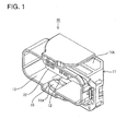
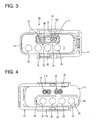
- FIGS. 1 to 10 One particular embodiment of the present invention is described with reference to FIGS. 1 to 10 .
- a connector for gas piping includes a connector housing main body 10, particularly substantially in the form of a receptacle with four rounded corners as shown in FIGS. 1 and 2 , and a sub-connector 30 having one or more gas or fluid tubes connected thereto as shown in FIG. 6 and is formed by at least partly fitting the sub-connector 30 into the connector housing main body 10 as shown in FIG. 9 .
- forward and backward directions are based on a lateral direction in FIG. 9 and a side of a connection surface (left side in FIG. 9 ) of the connector for gas piping is referred to as a front side.
- the connector housing main body 10 is made e.g. of synthetic resin, and a connecting lever 11 (as a particular movable member) which particularly substantially is U-shaped in front view and/or formed to substantially extend along the outer peripheral surface of the connector housing main body 10 is movably or displaceable (particularly rotatably or pivotably) supported on outer surfaces of the connector housing main body 10 as shown in FIGS. 1 to 4 .
- a connecting lever 11 as a particular movable member
- FIG. 1 at least one cam groove 12 is formed in (particularly each of) a pair of arm portions 11 A particularly substantially facing each other in this connecting lever 11.
- the (particularly both) cam groove(s) 12 is/are engageable with one or more, particularly a pair of cam pins 52 provided on a mating connector housing 51 of a mating connector 50.
- the one or more cam pins 52 are pulled toward back sides of the cam grooves 12 by a cam action generated by operating or displaying the connecting lever 11 (see FIG. 10 ). In this way, the respective connector housings 10, 51 are pulled toward each other to be connected or their connection is assisted.
- the connector housing main body 10 is formed with a receptacle 13 which substantially is open forward.
- One or more, particularly a pair of escaping grooves 15 extending from the opening of the receptacle 13 to the back wall of the receptacle 13 are formed at widthwise intermediate parts (particularly substantially central parts) of inner surfaces of the receptacle 13.
- the both escaping grooves 15 are formed substantially along entrance paths for the respective cam pins 52 of the mating connector housing 51 and/or guide the corresponding cam pins 52 to the cam grooves 12 of the connecting lever 11 when the mating connector housing 51 is at least partly inserted into the receptacle 13 to be connected.
- An electrical connector housing 16 is formed to substantially extend in forward and backward directions through the back wall of the receptacle 13 as shown in FIG. 10 .
- This electrical connector housing 16 includes a fitting tube portion 17 substantially extending forward from the back wall of the receptacle 13.
- a looped or rings-shaped seal member 18 including one or more lip portions 18A is to be mounted on or in the outer peripheral surface of (particularly a base end side of) this fitting tube portion 17.
- This seal member 18 seals between the electrical connector housings 16, 53 in a fluid- or liquid-tight manner when the fitting tube portion 17 is at least partly fitted into the mating electrical connector housing 53 in the form of a receptacle provided in the mating connector 50.
- One or more, particularly two pairs of cavities 19 are provided particularly adjacent to each other, each pair being spaced apart from the other, and particularly are arranged substantially side by side in the electrical connector housing 16.
- a flexible locking lance 20 (particularly substantially extending in a forward and inward direction in a cantilever manner) is provided at an inner surface of the (particularly each) cavity 19 as shown in FIG. 10 .
- This flexible locking lance 20 locks a female terminal fitting 21 at least partly inserted into the cavity 19 from an insertion side, particularly substantially from behind, to retain the female terminal fitting 21 in the cavity 19.
- a restricting tube portion 22 (particularly substantially in the form of a rectangular or polygonal tube) is mounted on or to (particularly a leading end portion of) the fitting tube portion 17.
- This restricting tube portion 22 includes one or more deformation restricting portions 22A (particularly substantially in the form of tongues), which can come into close contact with outer surfaces of the flexible locking lances 20 to prevent resilient deformation of the flexible locking lances 20 when the restricting tube portion 22 is mounted on the fitting tube portion 17.
- the sub-connector 30 includes a coupling plate 31 (particularly substantially in the form of a long and narrow plate) and one or more joint pipes 32 provided to penetrate through the coupling plate 31.
- the coupling plate 31 includes one or more inclined portions 31A formed by lower or outer parts of the opposite lateral (left and right) sides inclined inwardly, so that the width of the upper end surface is somewhat longer than that of the lower end surface.
- Each joint pipe 32 particularly has a tubular or substantially cylindrical shape and, as shown in FIGS. 6 to 8 , a plurality of (e.g. four) joint pipes 32 are so integrally or unitarily formed to the coupling plate 31 as to penetrate through plate surfaces of the coupling plate 31.
- One end of each joint pipe 32 before the coupling plate 31 serves as a pipe connecting portion 33 to be connected to a mating pipe 54 provided in the mating connector 50, and the other end at the rear side serves as a tube connecting portion 34 to be connected to a fluid or gas tube T.
- a continuous fluid or gas flow path 32A extending from the opening of the pipe connecting portion 33 to that of the tube connecting portion 34 is provided in each joint pipe 32.
- the pipe connecting portions 33 are so mounted as to substantially project forward from the back wall of the receptacle 13 when the sub-connector 30 is mounted into the connector housing main body 10.
- the one or more pipe connecting portions 33 are at least partly inserted and/or fitted into the mating pipes 54 provided in the mating connector housing 51.
- At least one first annular groove 33A having (or for at least partly accommodating) a first O-ring 35 mounted therein is formed in the outer peripheral surface of a leading end side of the pipe connecting portion 33.
- the first O-ring 35 particularly seals a clearance between the inner peripheral surface of the mating pipe 54 and the outer peripheral surface of the pipe connecting portion 33 in a fluid- or liquid-tight manner to prevent entrance of water and the like into the interiors of the pipes when the pipe connecting portion 33 is connected to the mating pipe 54.
- each tube connecting portion 34 is formed into at least one tapered portion 34A so that the tube connecting portion 34 can be easily at least partly inserted into the fluid or gas tube T.
- At least one annular engaging projection 34B outwardly widened from the rear side toward the front side (particularly substantially over the entire circumference) is formed on the outer peripheral surface of the tube connecting portion 34. This annular engaging projection 34B is to be engaged with the inner surface of the fluid or gas tube T to retain the tube connecting portion 34 in the gas tube T when the tube connecting portion 34 is at least partly inserted into the interior of the gas tube T.
- At least one second annular groove 33C having (or for at least partly accommodating) a second O-ring 36 mounted therein is formed in the outer peripheral surface of the tube connecting portion 34 behind or adjacent to the tapered portion 34A.
- the second O-ring 36 particularly seals a clearance between the inner peripheral surface of the fluid or gas tube T and the outer peripheral surface of the tube connecting portion 34 in a fluid- or liquid-tight manner to prevent entrance of water and the like into the interiors of the pipes when the tube connecting portion 34 is inserted into the gas tube T.
- a sub-connector accommodating portion 23 for at least partly accommodating the sub-connector 30 therein is provided ib or on (particularly the rear end surface of) the connector housing main body 10.
- the inner peripheral shape of the sub-connector 23 particularly is substantially the same as the outer peripheral shape of the sub-connector 30 when viewed from front as shown in FIG. 2 .
- the outer peripheral surface of the sub-connector 30 particularly is held in substantially close contact with the inner peripheral surface of the sub-connector accommodating portion 23.
- the one or more inclined portions 31 A provided at the outer or lower parts of the lateral (left and right) sides of the sub-connector 30 particularly function to position the sub-connector 30 when the sub-connector 30 is inserted into the sub-connector accommodating portion 23.
- one or more (e.g. four) pipe insertion holes 25 communicating with the receptacle 13 are formed in (particularly a back wall 24 of) the sub-connector accommodating portion 23.
- These pipe insertion holes 25 particularly are formed to be one size larger than the outer shape of the pipe connecting portions 33 of the sub-connector 30.
- the respective pipe insertion holes 25 are so set that the pipe connecting portions 33 are or can be respectively inserted into the corresponding pipe insertion holes 25 as shown in FIG. 10 when the sub-connector 30 is mounted into the sub-connector accommodating portion 23.
- one or more, particularly a pair of flexible engaging pieces 37 are formed on (particularly the substantially opposite side surfaces of) the coupling plate 31 of the sub-connector 30 facing in a width direction.
- Each of these flexible engaging pieces 37 includes an inclined piece 38 substantially extending from the front end of the side surface of the coupling plate 31 in a backward and outward direction particularly substantially in a cantilever manner and an engaging piece 39 extending further backward from the rear end surface of the inclined piece 38.
- a (particularly substantially rectangular or polygonal) engaging hole 39A is formed in an intermediate position (particularly in substantially the center) of the (particularly each) engaging piece 39.
- the one or more engaging holes 39A are engaged or engageable with one or more, particularly a pair of engaging projections 26 provided in the sub-connector accommodating portion 23 to retain the sub-connector 30 in the sub-connector accommodating portion 23 when the sub-connector 30 is at least partly inserted into the sub-connector accommodating portion 23.
- the engaging projections 26 particularly are inclined inwardly from the rear side to the front side.
- Leading end portions of the engaging pieces 39 serve as pressing/disengaging portions 40.
- This pair of pressing/disengaging portions 40 particularly press the sub-connector 30 from the substantially opposite widthwise sides toward the center of the coupling plate 31 at the time of separating the sub-connector 30 from the sub-connector accommodating portion 23. Then, the both flexible engaging pieces 37 are resiliently deformed to enable the sub-connector 30 to be separated from the sub-connector accommodating portion 23.
- the connector for gas piping of this embodiment is structured as described above. Next, a method for mounting the sub-connector 30 into the connector housing main body 10 is briefly described, and functions and effects of the connector for gas piping are also described in conjunction with the method.
- the respective tube connecting portions 34 of the sub-connector 30 are pressed into the gas tubes T beforehand to prepare the sub-connector 30 having a plurality of gas tubes T connected thereto (see FIGS. 6 to 8 ).
- the sub-connector 30 is positioned substantially in conformity with the shape of the opening of the sub-connector accommodating portion 23 of the connector housing main body 10 and/or at least partly inserted into the sub-connector accommodating portion 23.
- the one or more inclined pieces 38 of the one or more flexible engaging pieces 37 located at (particularly substantially the opposite widthwise sides of) the sub-connector 30 come into contact with the one or more engaging projections 26 of the sub-connector accommodating portion 23 to be pressed and the (particularly both) flexible engaging pieces 37 are resiliently deformed substantially toward the center of the coupling plate 31.
- the sub-connector 30 is further inserted particularly substantially until the front end surface of the coupling plate 31 comes into contact with the back wall 24 of the sub-connector accommodating portion 23.
- the one or more engaging projections 26 are engaged with the one or more respective engaging holes 39A of the one or more flexible engaging pieces 37 and a contact state of the flexible engaging pieces 37 and the engaging projections 26 is canceled.
- the flexible engaging pieces 37 are resiliently at least partly restored to retain the sub-connector 30 in the sub-connector accommodating portion 23.
- the gas tubes T can be mounted to the connector housing main body 10 by a very easy and simple operation only by inserting the sub-connector 30 into the sub-connector accommodating portion 23 of the connector housing main body 10. Further, in the case of detaching the sub-connector 30 from the connector housing main body 10 for maintenance or other reason, the sub-connector 30 can be very easily detached from the connector housing main body 10 particularly by pressing the one or more (particularly both) pressing/disengaging portions 40 laterally, particularly from the opposite widthwise sides toward the center of the coupling plate 31 to resiliently deform the flexible engaging pieces 37.
- a connector for fluid or gas piping for detachably connecting fluid or gas tubes T corresponding to mating pipes 54 provided in a mating connector 50 is provided with a connector housing main body 10 connectable to the mating connector 50, at least one sub-connector 30 provided in or on or at the connector housing main body 10, joint pipes 32 connectable to the mating pipes 54 and having the fluid or gas tubes T connected thereto, and an engaging mechanism for holding or engaging or locking the sub-connector 30 and the connector housing main body 10 in an engaged state.
Landscapes
- Engineering & Computer Science (AREA)
- General Engineering & Computer Science (AREA)
- Mechanical Engineering (AREA)
- Quick-Acting Or Multi-Walled Pipe Joints (AREA)
- Connector Housings Or Holding Contact Members (AREA)
Applications Claiming Priority (1)
| Application Number | Priority Date | Filing Date | Title |
|---|---|---|---|
| JP2010133976A JP5577868B2 (ja) | 2010-06-11 | 2010-06-11 | ガス配管用コネクタ |
Publications (2)
| Publication Number | Publication Date |
|---|---|
| EP2395272A1 true EP2395272A1 (fr) | 2011-12-14 |
| EP2395272B1 EP2395272B1 (fr) | 2014-04-30 |
Family
ID=44237695
Family Applications (1)
| Application Number | Title | Priority Date | Filing Date |
|---|---|---|---|
| EP11004112.6A Not-in-force EP2395272B1 (fr) | 2010-06-11 | 2011-05-18 | Connecteur pour canalisation de fluides, ensemble de connecteur et procédé de connexion de canalisation de fluides |
Country Status (5)
| Country | Link |
|---|---|
| US (1) | US8801046B2 (fr) |
| EP (1) | EP2395272B1 (fr) |
| JP (1) | JP5577868B2 (fr) |
| KR (1) | KR20110135811A (fr) |
| CN (1) | CN102313104A (fr) |
Families Citing this family (7)
| Publication number | Priority date | Publication date | Assignee | Title |
|---|---|---|---|---|
| CN104143739A (zh) * | 2014-07-22 | 2014-11-12 | 国家电网公司 | 一种便于接线的电网输电线及其连接方法 |
| KR101622675B1 (ko) * | 2015-09-25 | 2016-05-19 | 주식회사 큐라코 | 통합연결모듈을 포함하는 배설물 처리장치 |
| CN107355211A (zh) * | 2017-06-30 | 2017-11-17 | 中国海洋石油总公司 | 一种爬行器用多路油电连接器 |
| US10998665B2 (en) * | 2018-11-15 | 2021-05-04 | Medline Industries, Inc. | Hybrid connector |
| DE102020201428A1 (de) * | 2020-02-06 | 2021-08-12 | Alfmeier Präzision SE | Verbindungselement und Versorgungsleiste für eine Ventilanordnung |
| US11293576B2 (en) * | 2020-08-31 | 2022-04-05 | Caremed Supply Inc. | Gas supply connector |
| US20240200704A1 (en) * | 2022-12-15 | 2024-06-20 | Illinois Tool Works Inc. | Multi-Connector |
Citations (7)
| Publication number | Priority date | Publication date | Assignee | Title |
|---|---|---|---|---|
| DD61399A (fr) * | ||||
| FR1432838A (fr) * | 1965-02-26 | 1966-03-25 | Inst Werkzeugmaschinen | Raccord de tuyaux souples |
| US5775953A (en) * | 1995-05-16 | 1998-07-07 | Yazaki Corporation | Low-insertion-force connector assembly |
| FR2769136A1 (fr) * | 1997-09-29 | 1999-04-02 | Cinch Connecteurs Sa | Connecteur electrique |
| US20050046184A1 (en) * | 2003-09-03 | 2005-03-03 | Kai-Hsiang Chang | Apparatus for quick connection |
| EP1560298A1 (fr) * | 2004-02-02 | 2005-08-03 | Sumitomo Wiring Systems, Ltd. | Connecteur cloisonné et montage de connecteurs |
| WO2010027009A1 (fr) * | 2008-09-04 | 2010-03-11 | 住友電装株式会社 | Raccord |
Family Cites Families (14)
| Publication number | Priority date | Publication date | Assignee | Title |
|---|---|---|---|---|
| DE61399C (de) | H. KAWEL in Berlin S., Bärwaldstr. 11 III | Elastische Lagerung des Schiebers und Entlüftung des Gehäuses an Dampfwasser-Ableitern mit Drehschieber | ||
| BE636270A (fr) * | 1962-08-16 | |||
| US3469863A (en) * | 1967-04-05 | 1969-09-30 | Trico Products Corp | Fluid coupling assembly |
| JPS6133346Y2 (fr) * | 1980-11-12 | 1986-09-29 | ||
| JPS6128993U (ja) * | 1984-07-24 | 1986-02-21 | 小島プレス工業株式会社 | ホ−スの継手機構 |
| JPS6141096A (ja) * | 1984-08-02 | 1986-02-27 | 小島プレス工業株式会社 | ホ−スの継手機構 |
| US4804208A (en) * | 1986-08-11 | 1989-02-14 | The Kendall Company | Manifold coupling assembly |
| US4840574A (en) * | 1987-11-10 | 1989-06-20 | European Atomic Energy Community (Euratom) | Multiconnector |
| IT220672Z2 (it) * | 1990-11-13 | 1993-10-11 | Itw Fastex Italia Spa | Dispositivo di collegamento a scatto, a tenuta di fluido, per tubazioni |
| US5478119A (en) * | 1993-09-16 | 1995-12-26 | The Kendall Company | Polarized manifold connection device |
| US5588954A (en) * | 1994-04-05 | 1996-12-31 | Beiersdorf-Jobst, Inc. | Connector for a gradient sequential compression system |
| JP3709672B2 (ja) * | 1997-09-29 | 2005-10-26 | 東海ゴム工業株式会社 | 集束ホース用ワンタッチ接続装置 |
| FR2876775B1 (fr) * | 2004-10-14 | 2006-12-08 | Staubli Faverges Sca | Partie male d'un raccord rapide, ce raccord rapide et jeu de deux tels raccords rapides |
| US8092409B2 (en) * | 2007-05-18 | 2012-01-10 | Tyco Healthcare Group Lp | Reinforced connector |
-
2010
- 2010-06-11 JP JP2010133976A patent/JP5577868B2/ja not_active Expired - Fee Related
-
2011
- 2011-05-18 EP EP11004112.6A patent/EP2395272B1/fr not_active Not-in-force
- 2011-05-19 US US13/111,528 patent/US8801046B2/en not_active Expired - Fee Related
- 2011-06-02 KR KR1020110053395A patent/KR20110135811A/ko not_active Ceased
- 2011-06-03 CN CN2011101540569A patent/CN102313104A/zh active Pending
Patent Citations (8)
| Publication number | Priority date | Publication date | Assignee | Title |
|---|---|---|---|---|
| DD61399A (fr) * | ||||
| FR1432838A (fr) * | 1965-02-26 | 1966-03-25 | Inst Werkzeugmaschinen | Raccord de tuyaux souples |
| US5775953A (en) * | 1995-05-16 | 1998-07-07 | Yazaki Corporation | Low-insertion-force connector assembly |
| FR2769136A1 (fr) * | 1997-09-29 | 1999-04-02 | Cinch Connecteurs Sa | Connecteur electrique |
| US20050046184A1 (en) * | 2003-09-03 | 2005-03-03 | Kai-Hsiang Chang | Apparatus for quick connection |
| EP1560298A1 (fr) * | 2004-02-02 | 2005-08-03 | Sumitomo Wiring Systems, Ltd. | Connecteur cloisonné et montage de connecteurs |
| WO2010027009A1 (fr) * | 2008-09-04 | 2010-03-11 | 住友電装株式会社 | Raccord |
| JP2010062035A (ja) | 2008-09-04 | 2010-03-18 | Sumitomo Wiring Syst Ltd | コネクタ |
Also Published As
| Publication number | Publication date |
|---|---|
| JP5577868B2 (ja) | 2014-08-27 |
| CN102313104A (zh) | 2012-01-11 |
| JP2011258505A (ja) | 2011-12-22 |
| KR20110135811A (ko) | 2011-12-19 |
| US8801046B2 (en) | 2014-08-12 |
| EP2395272B1 (fr) | 2014-04-30 |
| US20110304133A1 (en) | 2011-12-15 |
Similar Documents
| Publication | Publication Date | Title |
|---|---|---|
| EP2395272A1 (fr) | Connecteur pour canalisation de fluides, ensemble de connecteur et procédé de connexion de canalisation de fluides | |
| US8608508B2 (en) | Rubber plug and waterproof connector | |
| US7488221B2 (en) | Connector | |
| US7252547B2 (en) | Connector | |
| US8177584B2 (en) | Connector with wire sealing resilient plug | |
| US8241062B2 (en) | Shielding connector and wire harness | |
| US6582242B2 (en) | Electrical connector with increased contact reliability | |
| US7104841B2 (en) | Watertight connector | |
| EP1737078A1 (fr) | Connecteur et metode d'assemblage du connecteur | |
| EP2390964A1 (fr) | Connecteur et ensemble de connecteur | |
| US7637764B2 (en) | Waterproof connector | |
| EP2390963B1 (fr) | Connecteur, ensemble de connecteur et procédé de production de connecteur | |
| US9147958B2 (en) | Connector | |
| US20010055907A1 (en) | Connector | |
| US20080064260A1 (en) | In-line sealed electrical connector apparatus | |
| US8485838B2 (en) | Lever-type connector with collective rubber stopper | |
| US20190312378A1 (en) | Connector with rubber cover | |
| US10050370B2 (en) | Rubber plug fixed by a plug holder to a cover fixed to a device | |
| JP2007305454A (ja) | コネクタ | |
| TWI469701B (zh) | A connector and a combination of the connector | |
| US9281600B2 (en) | Connector with retainer having reinforced escaping portion | |
| JP3433690B2 (ja) | ジョイントコネクタ | |
| JP2005216614A (ja) | 防水コネクタ | |
| JP2000243502A (ja) | ジョイントコネクタ | |
| JP2006172754A (ja) | 防水コネクタ |
Legal Events
| Date | Code | Title | Description |
|---|---|---|---|
| AK | Designated contracting states |
Kind code of ref document: A1 Designated state(s): AL AT BE BG CH CY CZ DE DK EE ES FI FR GB GR HR HU IE IS IT LI LT LU LV MC MK MT NL NO PL PT RO RS SE SI SK SM TR |
|
| AX | Request for extension of the european patent |
Extension state: BA ME |
|
| PUAI | Public reference made under article 153(3) epc to a published international application that has entered the european phase |
Free format text: ORIGINAL CODE: 0009012 |
|
| 17P | Request for examination filed |
Effective date: 20120315 |
|
| 17Q | First examination report despatched |
Effective date: 20130521 |
|
| GRAP | Despatch of communication of intention to grant a patent |
Free format text: ORIGINAL CODE: EPIDOSNIGR1 |
|
| INTG | Intention to grant announced |
Effective date: 20131206 |
|
| GRAS | Grant fee paid |
Free format text: ORIGINAL CODE: EPIDOSNIGR3 |
|
| GRAA | (expected) grant |
Free format text: ORIGINAL CODE: 0009210 |
|
| AK | Designated contracting states |
Kind code of ref document: B1 Designated state(s): AL AT BE BG CH CY CZ DE DK EE ES FI FR GB GR HR HU IE IS IT LI LT LU LV MC MK MT NL NO PL PT RO RS SE SI SK SM TR |
|
| REG | Reference to a national code |
Ref country code: GB Ref legal event code: FG4D Ref country code: CH Ref legal event code: EP |
|
| REG | Reference to a national code |
Ref country code: AT Ref legal event code: REF Ref document number: 665377 Country of ref document: AT Kind code of ref document: T Effective date: 20140515 |
|
| REG | Reference to a national code |
Ref country code: IE Ref legal event code: FG4D |
|
| REG | Reference to a national code |
Ref country code: DE Ref legal event code: R096 Ref document number: 602011006450 Country of ref document: DE Effective date: 20140612 |
|
| REG | Reference to a national code |
Ref country code: AT Ref legal event code: MK05 Ref document number: 665377 Country of ref document: AT Kind code of ref document: T Effective date: 20140430 |
|
| REG | Reference to a national code |
Ref country code: LT Ref legal event code: MG4D |
|
| REG | Reference to a national code |
Ref country code: NL Ref legal event code: VDEP Effective date: 20140430 |
|
| PG25 | Lapsed in a contracting state [announced via postgrant information from national office to epo] |
Ref country code: CY Free format text: LAPSE BECAUSE OF FAILURE TO SUBMIT A TRANSLATION OF THE DESCRIPTION OR TO PAY THE FEE WITHIN THE PRESCRIBED TIME-LIMIT Effective date: 20140430 Ref country code: NL Free format text: LAPSE BECAUSE OF FAILURE TO SUBMIT A TRANSLATION OF THE DESCRIPTION OR TO PAY THE FEE WITHIN THE PRESCRIBED TIME-LIMIT Effective date: 20140430 Ref country code: IS Free format text: LAPSE BECAUSE OF FAILURE TO SUBMIT A TRANSLATION OF THE DESCRIPTION OR TO PAY THE FEE WITHIN THE PRESCRIBED TIME-LIMIT Effective date: 20140830 Ref country code: GR Free format text: LAPSE BECAUSE OF FAILURE TO SUBMIT A TRANSLATION OF THE DESCRIPTION OR TO PAY THE FEE WITHIN THE PRESCRIBED TIME-LIMIT Effective date: 20140731 Ref country code: FI Free format text: LAPSE BECAUSE OF FAILURE TO SUBMIT A TRANSLATION OF THE DESCRIPTION OR TO PAY THE FEE WITHIN THE PRESCRIBED TIME-LIMIT Effective date: 20140430 Ref country code: BG Free format text: LAPSE BECAUSE OF FAILURE TO SUBMIT A TRANSLATION OF THE DESCRIPTION OR TO PAY THE FEE WITHIN THE PRESCRIBED TIME-LIMIT Effective date: 20140730 Ref country code: LT Free format text: LAPSE BECAUSE OF FAILURE TO SUBMIT A TRANSLATION OF THE DESCRIPTION OR TO PAY THE FEE WITHIN THE PRESCRIBED TIME-LIMIT Effective date: 20140430 Ref country code: NO Free format text: LAPSE BECAUSE OF FAILURE TO SUBMIT A TRANSLATION OF THE DESCRIPTION OR TO PAY THE FEE WITHIN THE PRESCRIBED TIME-LIMIT Effective date: 20140730 |
|
| PG25 | Lapsed in a contracting state [announced via postgrant information from national office to epo] |
Ref country code: HR Free format text: LAPSE BECAUSE OF FAILURE TO SUBMIT A TRANSLATION OF THE DESCRIPTION OR TO PAY THE FEE WITHIN THE PRESCRIBED TIME-LIMIT Effective date: 20140430 Ref country code: AT Free format text: LAPSE BECAUSE OF FAILURE TO SUBMIT A TRANSLATION OF THE DESCRIPTION OR TO PAY THE FEE WITHIN THE PRESCRIBED TIME-LIMIT Effective date: 20140430 Ref country code: ES Free format text: LAPSE BECAUSE OF FAILURE TO SUBMIT A TRANSLATION OF THE DESCRIPTION OR TO PAY THE FEE WITHIN THE PRESCRIBED TIME-LIMIT Effective date: 20140430 Ref country code: PL Free format text: LAPSE BECAUSE OF FAILURE TO SUBMIT A TRANSLATION OF THE DESCRIPTION OR TO PAY THE FEE WITHIN THE PRESCRIBED TIME-LIMIT Effective date: 20140430 Ref country code: SE Free format text: LAPSE BECAUSE OF FAILURE TO SUBMIT A TRANSLATION OF THE DESCRIPTION OR TO PAY THE FEE WITHIN THE PRESCRIBED TIME-LIMIT Effective date: 20140430 Ref country code: RS Free format text: LAPSE BECAUSE OF FAILURE TO SUBMIT A TRANSLATION OF THE DESCRIPTION OR TO PAY THE FEE WITHIN THE PRESCRIBED TIME-LIMIT Effective date: 20140430 Ref country code: LV Free format text: LAPSE BECAUSE OF FAILURE TO SUBMIT A TRANSLATION OF THE DESCRIPTION OR TO PAY THE FEE WITHIN THE PRESCRIBED TIME-LIMIT Effective date: 20140430 |
|
| PG25 | Lapsed in a contracting state [announced via postgrant information from national office to epo] |
Ref country code: PT Free format text: LAPSE BECAUSE OF FAILURE TO SUBMIT A TRANSLATION OF THE DESCRIPTION OR TO PAY THE FEE WITHIN THE PRESCRIBED TIME-LIMIT Effective date: 20140901 |
|
| REG | Reference to a national code |
Ref country code: CH Ref legal event code: PL |
|
| PG25 | Lapsed in a contracting state [announced via postgrant information from national office to epo] |
Ref country code: CZ Free format text: LAPSE BECAUSE OF FAILURE TO SUBMIT A TRANSLATION OF THE DESCRIPTION OR TO PAY THE FEE WITHIN THE PRESCRIBED TIME-LIMIT Effective date: 20140430 Ref country code: DK Free format text: LAPSE BECAUSE OF FAILURE TO SUBMIT A TRANSLATION OF THE DESCRIPTION OR TO PAY THE FEE WITHIN THE PRESCRIBED TIME-LIMIT Effective date: 20140430 Ref country code: BE Free format text: LAPSE BECAUSE OF FAILURE TO SUBMIT A TRANSLATION OF THE DESCRIPTION OR TO PAY THE FEE WITHIN THE PRESCRIBED TIME-LIMIT Effective date: 20140430 Ref country code: CH Free format text: LAPSE BECAUSE OF NON-PAYMENT OF DUE FEES Effective date: 20140531 Ref country code: EE Free format text: LAPSE BECAUSE OF FAILURE TO SUBMIT A TRANSLATION OF THE DESCRIPTION OR TO PAY THE FEE WITHIN THE PRESCRIBED TIME-LIMIT Effective date: 20140430 Ref country code: SK Free format text: LAPSE BECAUSE OF FAILURE TO SUBMIT A TRANSLATION OF THE DESCRIPTION OR TO PAY THE FEE WITHIN THE PRESCRIBED TIME-LIMIT Effective date: 20140430 Ref country code: MC Free format text: LAPSE BECAUSE OF FAILURE TO SUBMIT A TRANSLATION OF THE DESCRIPTION OR TO PAY THE FEE WITHIN THE PRESCRIBED TIME-LIMIT Effective date: 20140430 Ref country code: LI Free format text: LAPSE BECAUSE OF NON-PAYMENT OF DUE FEES Effective date: 20140531 Ref country code: RO Free format text: LAPSE BECAUSE OF FAILURE TO SUBMIT A TRANSLATION OF THE DESCRIPTION OR TO PAY THE FEE WITHIN THE PRESCRIBED TIME-LIMIT Effective date: 20140430 |
|
| REG | Reference to a national code |
Ref country code: DE Ref legal event code: R097 Ref document number: 602011006450 Country of ref document: DE |
|
| REG | Reference to a national code |
Ref country code: IE Ref legal event code: MM4A |
|
| PLBE | No opposition filed within time limit |
Free format text: ORIGINAL CODE: 0009261 |
|
| STAA | Information on the status of an ep patent application or granted ep patent |
Free format text: STATUS: NO OPPOSITION FILED WITHIN TIME LIMIT |
|
| 26N | No opposition filed |
Effective date: 20150202 |
|
| PG25 | Lapsed in a contracting state [announced via postgrant information from national office to epo] |
Ref country code: IE Free format text: LAPSE BECAUSE OF NON-PAYMENT OF DUE FEES Effective date: 20140518 |
|
| REG | Reference to a national code |
Ref country code: FR Ref legal event code: PLFP Year of fee payment: 5 |
|
| REG | Reference to a national code |
Ref country code: DE Ref legal event code: R097 Ref document number: 602011006450 Country of ref document: DE Effective date: 20150202 |
|
| PG25 | Lapsed in a contracting state [announced via postgrant information from national office to epo] |
Ref country code: SI Free format text: LAPSE BECAUSE OF FAILURE TO SUBMIT A TRANSLATION OF THE DESCRIPTION OR TO PAY THE FEE WITHIN THE PRESCRIBED TIME-LIMIT Effective date: 20140430 |
|
| PGFP | Annual fee paid to national office [announced via postgrant information from national office to epo] |
Ref country code: DE Payment date: 20150512 Year of fee payment: 5 Ref country code: GB Payment date: 20150513 Year of fee payment: 5 |
|
| PGFP | Annual fee paid to national office [announced via postgrant information from national office to epo] |
Ref country code: IT Payment date: 20150515 Year of fee payment: 5 Ref country code: FR Payment date: 20150508 Year of fee payment: 5 |
|
| PG25 | Lapsed in a contracting state [announced via postgrant information from national office to epo] |
Ref country code: MT Free format text: LAPSE BECAUSE OF FAILURE TO SUBMIT A TRANSLATION OF THE DESCRIPTION OR TO PAY THE FEE WITHIN THE PRESCRIBED TIME-LIMIT Effective date: 20140430 |
|
| PG25 | Lapsed in a contracting state [announced via postgrant information from national office to epo] |
Ref country code: SM Free format text: LAPSE BECAUSE OF FAILURE TO SUBMIT A TRANSLATION OF THE DESCRIPTION OR TO PAY THE FEE WITHIN THE PRESCRIBED TIME-LIMIT Effective date: 20140430 |
|
| PG25 | Lapsed in a contracting state [announced via postgrant information from national office to epo] |
Ref country code: TR Free format text: LAPSE BECAUSE OF FAILURE TO SUBMIT A TRANSLATION OF THE DESCRIPTION OR TO PAY THE FEE WITHIN THE PRESCRIBED TIME-LIMIT Effective date: 20140430 Ref country code: LU Free format text: LAPSE BECAUSE OF NON-PAYMENT OF DUE FEES Effective date: 20140518 Ref country code: HU Free format text: LAPSE BECAUSE OF FAILURE TO SUBMIT A TRANSLATION OF THE DESCRIPTION OR TO PAY THE FEE WITHIN THE PRESCRIBED TIME-LIMIT; INVALID AB INITIO Effective date: 20110518 |
|
| REG | Reference to a national code |
Ref country code: DE Ref legal event code: R119 Ref document number: 602011006450 Country of ref document: DE |
|
| GBPC | Gb: european patent ceased through non-payment of renewal fee |
Effective date: 20160518 |
|
| PG25 | Lapsed in a contracting state [announced via postgrant information from national office to epo] |
Ref country code: IT Free format text: LAPSE BECAUSE OF NON-PAYMENT OF DUE FEES Effective date: 20160518 |
|
| REG | Reference to a national code |
Ref country code: FR Ref legal event code: ST Effective date: 20170131 |
|
| PG25 | Lapsed in a contracting state [announced via postgrant information from national office to epo] |
Ref country code: DE Free format text: LAPSE BECAUSE OF NON-PAYMENT OF DUE FEES Effective date: 20161201 Ref country code: FR Free format text: LAPSE BECAUSE OF NON-PAYMENT OF DUE FEES Effective date: 20160531 |
|
| PG25 | Lapsed in a contracting state [announced via postgrant information from national office to epo] |
Ref country code: GB Free format text: LAPSE BECAUSE OF NON-PAYMENT OF DUE FEES Effective date: 20160518 |
|
| PG25 | Lapsed in a contracting state [announced via postgrant information from national office to epo] |
Ref country code: MK Free format text: LAPSE BECAUSE OF FAILURE TO SUBMIT A TRANSLATION OF THE DESCRIPTION OR TO PAY THE FEE WITHIN THE PRESCRIBED TIME-LIMIT Effective date: 20140430 |
|
| PG25 | Lapsed in a contracting state [announced via postgrant information from national office to epo] |
Ref country code: AL Free format text: LAPSE BECAUSE OF FAILURE TO SUBMIT A TRANSLATION OF THE DESCRIPTION OR TO PAY THE FEE WITHIN THE PRESCRIBED TIME-LIMIT Effective date: 20140430 |