EP2395300A2 - Fixation de toit - Google Patents
Fixation de toit Download PDFInfo
- Publication number
- EP2395300A2 EP2395300A2 EP11169503A EP11169503A EP2395300A2 EP 2395300 A2 EP2395300 A2 EP 2395300A2 EP 11169503 A EP11169503 A EP 11169503A EP 11169503 A EP11169503 A EP 11169503A EP 2395300 A2 EP2395300 A2 EP 2395300A2
- Authority
- EP
- European Patent Office
- Prior art keywords
- roof
- profile
- angle
- trapezoidal
- fastening
- Prior art date
- Legal status (The legal status is an assumption and is not a legal conclusion. Google has not performed a legal analysis and makes no representation as to the accuracy of the status listed.)
- Withdrawn
Links
- 230000001419 dependent effect Effects 0.000 claims 2
- 230000006978 adaptation Effects 0.000 description 3
- 238000010276 construction Methods 0.000 description 3
- XLYOFNOQVPJJNP-UHFFFAOYSA-N water Substances O XLYOFNOQVPJJNP-UHFFFAOYSA-N 0.000 description 2
- 238000000418 atomic force spectrum Methods 0.000 description 1
- 238000006073 displacement reaction Methods 0.000 description 1
- 238000005553 drilling Methods 0.000 description 1
- 230000000694 effects Effects 0.000 description 1
- 230000002349 favourable effect Effects 0.000 description 1
- 239000011521 glass Substances 0.000 description 1
- 238000004519 manufacturing process Methods 0.000 description 1
- 230000003014 reinforcing effect Effects 0.000 description 1
- 238000010079 rubber tapping Methods 0.000 description 1
- 238000007789 sealing Methods 0.000 description 1
Images



Classifications
-
- F—MECHANICAL ENGINEERING; LIGHTING; HEATING; WEAPONS; BLASTING
- F24—HEATING; RANGES; VENTILATING
- F24S—SOLAR HEAT COLLECTORS; SOLAR HEAT SYSTEMS
- F24S25/00—Arrangement of stationary mountings or supports for solar heat collector modules
- F24S25/60—Fixation means, e.g. fasteners, specially adapted for supporting solar heat collector modules
- F24S25/61—Fixation means, e.g. fasteners, specially adapted for supporting solar heat collector modules for fixing to the ground or to building structures
-
- F—MECHANICAL ENGINEERING; LIGHTING; HEATING; WEAPONS; BLASTING
- F24—HEATING; RANGES; VENTILATING
- F24S—SOLAR HEAT COLLECTORS; SOLAR HEAT SYSTEMS
- F24S25/00—Arrangement of stationary mountings or supports for solar heat collector modules
- F24S25/60—Fixation means, e.g. fasteners, specially adapted for supporting solar heat collector modules
- F24S25/61—Fixation means, e.g. fasteners, specially adapted for supporting solar heat collector modules for fixing to the ground or to building structures
- F24S25/615—Fixation means, e.g. fasteners, specially adapted for supporting solar heat collector modules for fixing to the ground or to building structures for fixing to protruding parts of buildings, e.g. to corrugations or to standing seams
-
- F—MECHANICAL ENGINEERING; LIGHTING; HEATING; WEAPONS; BLASTING
- F24—HEATING; RANGES; VENTILATING
- F24S—SOLAR HEAT COLLECTORS; SOLAR HEAT SYSTEMS
- F24S25/00—Arrangement of stationary mountings or supports for solar heat collector modules
- F24S25/60—Fixation means, e.g. fasteners, specially adapted for supporting solar heat collector modules
- F24S2025/6006—Fixation means, e.g. fasteners, specially adapted for supporting solar heat collector modules by using threaded elements, e.g. stud bolts
-
- Y—GENERAL TAGGING OF NEW TECHNOLOGICAL DEVELOPMENTS; GENERAL TAGGING OF CROSS-SECTIONAL TECHNOLOGIES SPANNING OVER SEVERAL SECTIONS OF THE IPC; TECHNICAL SUBJECTS COVERED BY FORMER USPC CROSS-REFERENCE ART COLLECTIONS [XRACs] AND DIGESTS
- Y02—TECHNOLOGIES OR APPLICATIONS FOR MITIGATION OR ADAPTATION AGAINST CLIMATE CHANGE
- Y02B—CLIMATE CHANGE MITIGATION TECHNOLOGIES RELATED TO BUILDINGS, e.g. HOUSING, HOUSE APPLIANCES OR RELATED END-USER APPLICATIONS
- Y02B10/00—Integration of renewable energy sources in buildings
- Y02B10/20—Solar thermal
-
- Y—GENERAL TAGGING OF NEW TECHNOLOGICAL DEVELOPMENTS; GENERAL TAGGING OF CROSS-SECTIONAL TECHNOLOGIES SPANNING OVER SEVERAL SECTIONS OF THE IPC; TECHNICAL SUBJECTS COVERED BY FORMER USPC CROSS-REFERENCE ART COLLECTIONS [XRACs] AND DIGESTS
- Y02—TECHNOLOGIES OR APPLICATIONS FOR MITIGATION OR ADAPTATION AGAINST CLIMATE CHANGE
- Y02E—REDUCTION OF GREENHOUSE GAS [GHG] EMISSIONS, RELATED TO ENERGY GENERATION, TRANSMISSION OR DISTRIBUTION
- Y02E10/00—Energy generation through renewable energy sources
- Y02E10/40—Solar thermal energy, e.g. solar towers
- Y02E10/47—Mountings or tracking
Definitions
- the invention relates to a roof attachment for a roof with a trapezoidal roof profile.
- the invention has for its object to provide a roof attachment for a trapezoidal roof profile, which is particularly flexible attachable and at the same time overbuilding existing on the roof roof screws u. ⁇ . allowed.
- the roof fastening according to the invention has a trapezoidal element with a fastening bore and at least one slot and at least one profile element.
- An advantage of this invention is that the combination of the trapezoidal element with the profile element, the possibility is opened to overbuild existing on the roof roof screws.
- the profile element allows a particularly high stability when mounted on a trapezoidal roof profile or on a roof structure.
- the profile element further has the advantage that between the roof profile and the trapezoidal element can form a gap. This distance can serve as a circulation option or be used in other ways, for example as a cable channel.
- the trapezoidal element is formed as a one-piece, three-legged component.
- the roof fastening consists only of two components (three-legged component and Profile element), which reduces the manufacturing effort and the susceptibility to assembly errors.
- the trapezoidal element consists of a first angle element and a second angle element, each having at least one mounting hole and in each case at least one elongated hole.
- the trapezoidal element is formed from a first angle element and a second angle element, which are each formed as a separate component.
- the trapezoidal element consists of two separate components.
- Each of the angle elements has at least one mounting hole and at least one slot.
- the mounting hole (s) are used for attachment of fasteners to the roof profile, so as to connect the angle elements or the trapezoidal element releasably or permanently connected to the respective roof profile.
- the trapezoidal element is formed from two angle elements, fastening bores can be arranged on an angle side of one of the angle elements to be fastened to the trapezoidal roof profile.
- An advantage of this embodiment is that already fixing holes are predetermined and only one fastener or a connecting element must be introduced into the mounting holes. Thus, no further holes in the angle element must be introduced to the Angle element to attach to the roof profile. At the same time, a particularly non-slip and therefore also tight connection between angle elements and roof profile is achieved.
- the flexibility of the elongated holes of the angle members provides the opportunity to achieve a precise adaptation to the roof profile, which entails minimizing the deformation of the roof profile and increasing the tightness of the connection against the effects of the weather.
- the profile element may be a DIN rail or a U-profile.
- An advantage of a top hat rail is the special stability that it has. Due to the side arms placed on a U-profile, a DIN rail can rest on surfaces and thus allows an increased surface contact, which improves the steadfastness of the DIN rail on the roof and / or a roof structure.
- a U-profile can also be used as it is inexpensive to buy.
- the profile element can e.g. serve for the buildability of roof screws.
- the two angle elements can be attached via such a profile element under clamping on the roof structure.
- the profile element may have a bore in its middle part. Through the hole in the middle part of the profile element, the profile element can be connected by means of a connecting element with the first and the second angle element or with the trapezoidal element. Furthermore, it is possible to fix the profile element with its bore in the middle part fixed or releasably attached to the roof profile and / or to a roof structure. A centered structure of the elements with only one connecting element generates a particularly favorable force curve.
- the first angle element and the second angle element can be interconnected by their slots and through the bore of the profile element.
- the connection of the individual elements creates the Roof attachment, which can be placed on a trapezoidal roof profile.
- the connection between the first and the second angle element and the profile element is effected by a connecting element.
- the connecting element may be a bolt, a screw, a nail or the like.
- the slots of the angle elements can be arranged centrally on a surface of the respective angle element Due to the central position of the elongated holes on the angle element is provided with an arrangement of two angle elements one above the other (first and second angle element and profile element) only a small space consumption of the roof attachment.
- the first and second angle element are conclusive and compatible one above the other.
- a roof structure is attached to the roof fastening. Furthermore, it allows the roof attachment to install a roof structure on a trapezoidal roof profile.
- a roof construction can u.a. a solar panel, a photovoltaic system, a cable channel or a water storage, as these are common, for example, in the US, be.
- the intermediate element has the advantage of allowing accurate adjustment of the roof structure, such as in solar or photovoltaic systems, the optimal orientation to the sun at a certain angle or an optimal Need mount on the roof mount.
- the intermediate element may be an angle or another profile element.
- the intermediate element is connected by a further profile element with the roof fastening.
- a further profile element with the roof fastening.
- the further profile element is used here to produce a high stability. Roof structures, such as solar, photovoltaic or water storage, are exposed to high loads, such as wind, rain, snow or other weather-related influences. A particularly high stability of roof structures is thus required.
- a connecting element in the bore of the profile element and the slots of the angle elements can be used.
- the connecting element serves for the connection between the two angle elements and at least one profile element.
- the connecting element may be a screw, a nail or a bolt.
- the in the FIGS. 1 to 4 Roof attachment 1 shown consists of a first angle element 3, a second angle element 4 and a profile element 7.
- the first angle element 3 and the second angle element 4 form the trapezoidal element.
- Fig. 1 shows an exploded view of the roof attachment 1.
- the trapezoidal roof profile 2 has in this illustration holes 6, which allow to accommodate at least one angle element 3.4.
- the angle element 3,4 can be a corrugation 16 (see. Fig. 3 - in Fig. 1 not shown).
- a shim 13 eg a rubber seal
- the shim 13 may also have holes which are compatible with the holes 6 of the angle elements 3,4 and the mounting holes 6 of the trapezoidal roof profile 2. The latter can also be produced by self-tapping screws.
- the mounting holes 6 of the trapezoidal roof profile 2 are mounted in overlapping trapezoidal roof profiles 2 in particular in the overlapping region of the trapezoidal roof profiles 2, whereby a particularly high density of the roof fastening is achieved.
- the shim 13 serves to transmit power to a fastener and to avoid deformation of the roof fastening 1 and / or on the trapezoidal roof profile 2.
- the connecting element 11 connects the profile element 7, the shown here as DIN rail, with the second angle element 4 and the first angle element 3. In order to achieve a low construction of the individual elements of the roof fastening 1, it is possible to introduce countersunk screws as a connecting element 11. Between profile element 7 and the roof profile 2, for example, to protect the roof profile 2, a sealing element may be mounted (not shown).
- a washer 10 is applied to the connecting element 11 and the connecting element is passed through a bore 8 of the profile element 7. If the profile element 7 is arranged on the connecting element 11, the second angle element 4 and then the first angle element 3 are arranged on the connecting element 11 through their respective elongated holes 5. In this illustration of the innovation is finally, after the profile element 7 and the two angle elements 3.4 are arranged on the connecting element 11, a further washer 10 for transmitting power and preventing deformation applied to the connecting element 11 and secured with a nut.
- the connecting element 11 is formed in this illustration as a screw or as a bolt and secured by a nut 12.
- the angle elements 3,4 have on the surface which is to be attached to the trapezoidal roof profile 2, two mounting holes 6, which are compatible in arrangement with the holes of the washer 13 and the mounting holes 6 of the trapezoidal roof profile 2.
- the elongated holes 5 of the angle elements 3,4 are arranged on the respective second surface of the angle element.
- the elongated holes 5 of the angle elements 3,4 and the bore 8 of the profile element 7 are introduced in this embodiment of the innovation in each case centrally in the profile element 7 and / or the angle element 3.4.
- Fig. 2 is a sectional view in an assembled embodiment of Fig. 1 ,
- the profile element 7, here again a hat rail, is stable with its arms on the trapezoidal roof profile 2.
- the DIN rail is through the Connecting element 11 connected to the first and second angle elements 3.4.
- a conventional angle can be attached, can be attached to the structures (not shown).
- the angle elements 3,4 have been arranged on the trapezoidal roof profile 2 so that they can adapt to their width. This is achieved by the elongated holes 5, which can achieve a shift in the angle elements 3.4 and thus the respective roof profile is customizable.
- the first angle element 3 is made longer in this embodiment in the area in which the slot 5 is located. It is also possible to form the first and the second angle element 3,4 similarly.
- the connecting element 11, which connects the top-hat rail and the first and second angle element 3, 4, closes the connection with a nut 12.
- FIG Fig. 3 An exploded view of another embodiment of the invention is shown in FIG Fig. 3 shown.
- the presentation is similar Fig. 1
- another profile element 7.1 is arranged.
- the profile element 7.1 is formed as a DIN rail.
- the DIN rail is also arranged on the connecting element 11.
- a washer 10 is applied to the connecting element 11, then the profile element 7, the second angle element 4 and the first angle element 3.
- the roof fastening 1 is completed by the arrangement of a further profile element 7.1, which may be a DIN rail as shown here.
- a further washer 10 and a nut 12 on the connecting element 11 can be attached.
- the washers 10 may also be snap rings. It is also possible that the nut is designed with a toothing.
- a corrugation 16 of the second angle element 4 is shown.
- the corrugation 16 may be wholly or partially attached to the individual surfaces of the angle elements 3, 4.
- the corrugation of the surface allows for a connection of the individual elements, slippage or displacement of the angle elements 3,4 is mutually avoidable, since the surfaces of the angle elements 3,4 interlock with each other and so further movement is difficult.
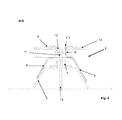
- Fig. 4 shows a section of a mounted roof fastening, as in Fig. 3 shown.
- a roof structure 14 is shown, which is connected by means of a further profile element 7.1 and an intermediate element 9 with the roof fastening 1.
- the trapezoidal roof profile 2 is fastened to the roof with a second connecting element 15 (eg a roof screw already present in the roof profile 2), so that the trapezoidal roof profile 2 gains in stability.
- the profile element 7 is arranged, which covers the second connecting element 15 with its opening. This creates a possibility for over-expansion of existing roofing screws by the renewal roof fastening 1.
- a first connecting element 11 carries the profile element 7, and the second and the first angle element 3.4.
- an intermediate element 9 is attached to both sides of the profile element 7.1.
- the intermediate element 9 is shown in this embodiment as a U-profile rail, but it is also possible to form the intermediate element as a simple rail or form in any other way as a fastener and / or as a reinforcing element.
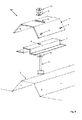
- the in the FIGS. 5 to 6 illustrated roof mount 101 differs from that in the FIGS. 1 to 4 illustrated embodiments by the differently configured trapezoidal element. While in the first and second embodiments, the trapezoidal element is formed of the first angle element 3 and the second angle element 4, the trapezoidal element in the third embodiment consists of a one-piece, three-legged component 17. The remaining components are not different from each other, so to the corresponding description to the FIGS. 1 to 4 can be referenced.
- Fig. 5 shows an exploded view of the roof attachment 101.
- Fig. 6 shows a sectional view along the longitudinal axis of the roof profile 2.
- the roof fastening 101 has a three-legged component 17 and a profile element 7.
- the three-legged component 17 has a slot 5 and a plurality of fastening bores 6.
- the profile element 7 has a bore 8.
- the three-legged component 17 and the profile element 7 are interconnected by a connecting element 11, which is introduced into the bore 8 and the slot 5.
- the connecting element 11 is designed as a screw, which is provided with washers 10 and a nut.
Landscapes
- Engineering & Computer Science (AREA)
- Physics & Mathematics (AREA)
- Life Sciences & Earth Sciences (AREA)
- Sustainable Development (AREA)
- Sustainable Energy (AREA)
- Thermal Sciences (AREA)
- Chemical & Material Sciences (AREA)
- Combustion & Propulsion (AREA)
- Mechanical Engineering (AREA)
- General Engineering & Computer Science (AREA)
- Roof Covering Using Slabs Or Stiff Sheets (AREA)
- Vehicle Step Arrangements And Article Storage (AREA)
Applications Claiming Priority (2)
| Application Number | Priority Date | Filing Date | Title |
|---|---|---|---|
| DE202010005612U DE202010005612U1 (de) | 2010-06-10 | 2010-06-10 | Dachbefestigung |
| DE202011000893U DE202011000893U1 (de) | 2010-06-10 | 2011-04-15 | Dachbefestigung |
Publications (2)
| Publication Number | Publication Date |
|---|---|
| EP2395300A2 true EP2395300A2 (fr) | 2011-12-14 |
| EP2395300A3 EP2395300A3 (fr) | 2012-06-06 |
Family
ID=42675400
Family Applications (1)
| Application Number | Title | Priority Date | Filing Date |
|---|---|---|---|
| EP11169503A Withdrawn EP2395300A3 (fr) | 2010-06-10 | 2011-06-10 | Fixation de toit |
Country Status (2)
| Country | Link |
|---|---|
| EP (1) | EP2395300A3 (fr) |
| DE (2) | DE202010005612U1 (fr) |
Families Citing this family (6)
| Publication number | Priority date | Publication date | Assignee | Title |
|---|---|---|---|---|
| ITTO20100178U1 (it) * | 2010-11-19 | 2012-05-20 | Gian Luca Ruffa | Dispositivo per l'ancoraggio di pannelli solari su coperture di edifici |
| ITTO20110724A1 (it) * | 2011-08-04 | 2013-02-05 | G & B Fissaggi S R L | Staffa per il fissaggio di pannelli fotovoltaici. |
| ITFI20110163A1 (it) * | 2011-08-05 | 2013-02-06 | Bees S R L | Sistema per fissare pannelli o moduli fotovoltaici su coperture di edifici. |
| FR2983500B1 (fr) * | 2011-12-05 | 2017-03-24 | Sas Solarsit | Systeme de fixation permettant de fixer un rail support de panneau a un element de couverture |
| FR3041835B1 (fr) * | 2015-09-28 | 2020-02-07 | Adiwatt | Mecanisme de fixation de panneaux solaires sur des plaques metalliques formant un toit. |
| US10547270B2 (en) | 2016-02-12 | 2020-01-28 | Solarcity Corporation | Building integrated photovoltaic roofing assemblies and associated systems and methods |
Family Cites Families (4)
| Publication number | Priority date | Publication date | Assignee | Title |
|---|---|---|---|---|
| DE202009003124U1 (de) * | 2009-03-09 | 2009-05-20 | C&L Gmbh | Halterung für Unterkonstruktion von Solarmodulen sowie Unterkonstruktion von Solarmodulen |
| DE202009003862U1 (de) * | 2009-03-19 | 2009-06-10 | Mounting Systems Gmbh | Abstützvorrichtung für Funktionsaufbauten auf Dächern |
| DE202009004269U1 (de) * | 2009-03-31 | 2009-06-04 | C&L Gmbh | Halterung für Solarmodule zur Aufstellung auf einer Aufstellfläche |
| DE202010012937U1 (de) * | 2010-11-19 | 2011-01-20 | Kreitmair, Georg | Befestigungssystem |
-
2010
- 2010-06-10 DE DE202010005612U patent/DE202010005612U1/de not_active Expired - Lifetime
-
2011
- 2011-04-15 DE DE202011000893U patent/DE202011000893U1/de not_active Expired - Lifetime
- 2011-06-10 EP EP11169503A patent/EP2395300A3/fr not_active Withdrawn
Non-Patent Citations (1)
| Title |
|---|
| None |
Also Published As
| Publication number | Publication date |
|---|---|
| DE202011000893U1 (de) | 2011-08-11 |
| EP2395300A3 (fr) | 2012-06-06 |
| DE202010005612U1 (de) | 2010-09-02 |
Similar Documents
| Publication | Publication Date | Title |
|---|---|---|
| EP2672034B1 (fr) | Pied de support pour le guidage et la distribution de forces sur un sous-sol sensible à la pression et système de support doté d'un tel pied de support | |
| EP2430666B1 (fr) | Ensemble support pour modules solaires | |
| DE102018221183B3 (de) | Justierbeschlag und Tragsystem für Solarmodule | |
| DE202011000893U1 (de) | Dachbefestigung | |
| DE102012007535A1 (de) | Verbindungselement zum Verbinden eines ersten Bauteils eines Gestells einer Photovoltaik- und/oder Solarthermieanlage mit einem zweiten Bauteil und Gestell einer Photovoltalk- und/oder Solarthermieanlage | |
| DE102007010073B4 (de) | Verbindungssystem für Rinnenunterteile | |
| EP1348916A2 (fr) | Dispositif de fixation pour des élements de construction, en spéciale des collecteurs | |
| DE202010007000U1 (de) | Trapezdach-Befestigungsvorrichtung | |
| DE202009015122U1 (de) | Vorrichtung zum Abstützen von Solarmodulen | |
| DE202009016197U1 (de) | Zur Befestigung eines Gegenstandes dienendes Halteelement und Befestigungseinrichtung für Solarmodule | |
| DE102004049595B3 (de) | Dachhaken | |
| DE102019108036A1 (de) | Überdachungssystem sowie Trägermodul hierfür | |
| EP2400239B1 (fr) | Dispositif de réglage et système de montage | |
| DE102014106068B4 (de) | Vorrichtung zur Verbindung zweier einander gegenüberliegender plattenförmiger Schalungselemente | |
| DE102017217183B3 (de) | Eck- und/oder Stoßverbindung | |
| DE202018106077U1 (de) | Glasträgerkonstruktion und Rahmenkonstruktion | |
| DE102008006251A1 (de) | Bodenbelag | |
| EP4274093B1 (fr) | Système de montage pour modules photovoltaïques et composants de système de montage pour modules photovoltaïques améliorant l'installation | |
| DE102016219989A1 (de) | Nachführbare Trägervorrichtung mit Schneckengetriebe für Solarmodule | |
| WO2013083265A1 (fr) | Elément de support pour un lève-glace pour véhicule automobile avec structure de renforcement | |
| EP3798383B1 (fr) | Dispositif de retenue et procédé de fabrication d'une façade | |
| EP2055856B1 (fr) | Structure de toit | |
| DE102010028566A1 (de) | Solarmodultragvorrichtung | |
| DE102009010222B4 (de) | Fluchtend durch mindestens eine Verbindungsanordnung miteinander verbundene Doppelstab- oder Flachstab- oder kombinierte Doppelstab-Flachstab-Gittermatten | |
| DE102007055479B4 (de) | Knotenelement für eine Fachwerkskonstruktion |
Legal Events
| Date | Code | Title | Description |
|---|---|---|---|
| AK | Designated contracting states |
Kind code of ref document: A2 Designated state(s): AL AT BE BG CH CY CZ DE DK EE ES FI FR GB GR HR HU IE IS IT LI LT LU LV MC MK MT NL NO PL PT RO RS SE SI SK SM TR |
|
| AX | Request for extension of the european patent |
Extension state: BA ME |
|
| PUAI | Public reference made under article 153(3) epc to a published international application that has entered the european phase |
Free format text: ORIGINAL CODE: 0009012 |
|
| PUAL | Search report despatched |
Free format text: ORIGINAL CODE: 0009013 |
|
| AK | Designated contracting states |
Kind code of ref document: A3 Designated state(s): AL AT BE BG CH CY CZ DE DK EE ES FI FR GB GR HR HU IE IS IT LI LT LU LV MC MK MT NL NO PL PT RO RS SE SI SK SM TR |
|
| AX | Request for extension of the european patent |
Extension state: BA ME |
|
| RIC1 | Information provided on ipc code assigned before grant |
Ipc: F24J 2/52 20060101AFI20120503BHEP Ipc: F16B 5/02 20060101ALI20120503BHEP |
|
| STAA | Information on the status of an ep patent application or granted ep patent |
Free format text: STATUS: THE APPLICATION IS DEEMED TO BE WITHDRAWN |
|
| 18D | Application deemed to be withdrawn |
Effective date: 20121207 |