EP2395304A2 - Procédé de contrôle pour réfrigérateur - Google Patents
Procédé de contrôle pour réfrigérateur Download PDFInfo
- Publication number
- EP2395304A2 EP2395304A2 EP11004847A EP11004847A EP2395304A2 EP 2395304 A2 EP2395304 A2 EP 2395304A2 EP 11004847 A EP11004847 A EP 11004847A EP 11004847 A EP11004847 A EP 11004847A EP 2395304 A2 EP2395304 A2 EP 2395304A2
- Authority
- EP
- European Patent Office
- Prior art keywords
- freezer
- fridge
- evaporator
- fan
- time
- Prior art date
- Legal status (The legal status is an assumption and is not a legal conclusion. Google has not performed a legal analysis and makes no representation as to the accuracy of the status listed.)
- Granted
Links
Images




Classifications
-
- F—MECHANICAL ENGINEERING; LIGHTING; HEATING; WEAPONS; BLASTING
- F25—REFRIGERATION OR COOLING; COMBINED HEATING AND REFRIGERATION SYSTEMS; HEAT PUMP SYSTEMS; MANUFACTURE OR STORAGE OF ICE; LIQUEFACTION SOLIDIFICATION OF GASES
- F25D—REFRIGERATORS; COLD ROOMS; ICE-BOXES; COOLING OR FREEZING APPARATUS NOT OTHERWISE PROVIDED FOR
- F25D29/00—Arrangement or mounting of control or safety devices
-
- F—MECHANICAL ENGINEERING; LIGHTING; HEATING; WEAPONS; BLASTING
- F25—REFRIGERATION OR COOLING; COMBINED HEATING AND REFRIGERATION SYSTEMS; HEAT PUMP SYSTEMS; MANUFACTURE OR STORAGE OF ICE; LIQUEFACTION SOLIDIFICATION OF GASES
- F25D—REFRIGERATORS; COLD ROOMS; ICE-BOXES; COOLING OR FREEZING APPARATUS NOT OTHERWISE PROVIDED FOR
- F25D17/00—Arrangements for circulating cooling fluids; Arrangements for circulating gas, e.g. air, within refrigerated spaces
- F25D17/04—Arrangements for circulating cooling fluids; Arrangements for circulating gas, e.g. air, within refrigerated spaces for circulating air, e.g. by convection
- F25D17/06—Arrangements for circulating cooling fluids; Arrangements for circulating gas, e.g. air, within refrigerated spaces for circulating air, e.g. by convection by forced circulation
- F25D17/062—Arrangements for circulating cooling fluids; Arrangements for circulating gas, e.g. air, within refrigerated spaces for circulating air, e.g. by convection by forced circulation in household refrigerators
- F25D17/065—Arrangements for circulating cooling fluids; Arrangements for circulating gas, e.g. air, within refrigerated spaces for circulating air, e.g. by convection by forced circulation in household refrigerators with compartments at different temperatures
-
- F—MECHANICAL ENGINEERING; LIGHTING; HEATING; WEAPONS; BLASTING
- F25—REFRIGERATION OR COOLING; COMBINED HEATING AND REFRIGERATION SYSTEMS; HEAT PUMP SYSTEMS; MANUFACTURE OR STORAGE OF ICE; LIQUEFACTION SOLIDIFICATION OF GASES
- F25B—REFRIGERATION MACHINES, PLANTS OR SYSTEMS; COMBINED HEATING AND REFRIGERATION SYSTEMS; HEAT PUMP SYSTEMS
- F25B2400/00—Component parts or details not otherwise provided for in this subclass
- F25B2400/19—Pumping down refrigerant from one part of the cycle to another part of the cycle, e.g. when the cycle is changed from cooling to heating, or before a defrost cycle is started
-
- F—MECHANICAL ENGINEERING; LIGHTING; HEATING; WEAPONS; BLASTING
- F25—REFRIGERATION OR COOLING; COMBINED HEATING AND REFRIGERATION SYSTEMS; HEAT PUMP SYSTEMS; MANUFACTURE OR STORAGE OF ICE; LIQUEFACTION SOLIDIFICATION OF GASES
- F25B—REFRIGERATION MACHINES, PLANTS OR SYSTEMS; COMBINED HEATING AND REFRIGERATION SYSTEMS; HEAT PUMP SYSTEMS
- F25B2600/00—Control issues
- F25B2600/01—Timing
-
- F—MECHANICAL ENGINEERING; LIGHTING; HEATING; WEAPONS; BLASTING
- F25—REFRIGERATION OR COOLING; COMBINED HEATING AND REFRIGERATION SYSTEMS; HEAT PUMP SYSTEMS; MANUFACTURE OR STORAGE OF ICE; LIQUEFACTION SOLIDIFICATION OF GASES
- F25B—REFRIGERATION MACHINES, PLANTS OR SYSTEMS; COMBINED HEATING AND REFRIGERATION SYSTEMS; HEAT PUMP SYSTEMS
- F25B2600/00—Control issues
- F25B2600/11—Fan speed control
- F25B2600/112—Fan speed control of evaporator fans
-
- F—MECHANICAL ENGINEERING; LIGHTING; HEATING; WEAPONS; BLASTING
- F25—REFRIGERATION OR COOLING; COMBINED HEATING AND REFRIGERATION SYSTEMS; HEAT PUMP SYSTEMS; MANUFACTURE OR STORAGE OF ICE; LIQUEFACTION SOLIDIFICATION OF GASES
- F25B—REFRIGERATION MACHINES, PLANTS OR SYSTEMS; COMBINED HEATING AND REFRIGERATION SYSTEMS; HEAT PUMP SYSTEMS
- F25B2600/00—Control issues
- F25B2600/25—Control of valves
- F25B2600/2511—Evaporator distribution valves
-
- F—MECHANICAL ENGINEERING; LIGHTING; HEATING; WEAPONS; BLASTING
- F25—REFRIGERATION OR COOLING; COMBINED HEATING AND REFRIGERATION SYSTEMS; HEAT PUMP SYSTEMS; MANUFACTURE OR STORAGE OF ICE; LIQUEFACTION SOLIDIFICATION OF GASES
- F25B—REFRIGERATION MACHINES, PLANTS OR SYSTEMS; COMBINED HEATING AND REFRIGERATION SYSTEMS; HEAT PUMP SYSTEMS
- F25B45/00—Arrangements for charging or discharging refrigerant
-
- F—MECHANICAL ENGINEERING; LIGHTING; HEATING; WEAPONS; BLASTING
- F25—REFRIGERATION OR COOLING; COMBINED HEATING AND REFRIGERATION SYSTEMS; HEAT PUMP SYSTEMS; MANUFACTURE OR STORAGE OF ICE; LIQUEFACTION SOLIDIFICATION OF GASES
- F25D—REFRIGERATORS; COLD ROOMS; ICE-BOXES; COOLING OR FREEZING APPARATUS NOT OTHERWISE PROVIDED FOR
- F25D2317/00—Details or arrangements for circulating cooling fluids; Details or arrangements for circulating gas, e.g. air, within refrigerated spaces, not provided for in other groups of this subclass
- F25D2317/06—Details or arrangements for circulating cooling fluids; Details or arrangements for circulating gas, e.g. air, within refrigerated spaces, not provided for in other groups of this subclass with forced air circulation
- F25D2317/068—Details or arrangements for circulating cooling fluids; Details or arrangements for circulating gas, e.g. air, within refrigerated spaces, not provided for in other groups of this subclass with forced air circulation characterised by the fans
- F25D2317/0682—Two or more fans
-
- Y—GENERAL TAGGING OF NEW TECHNOLOGICAL DEVELOPMENTS; GENERAL TAGGING OF CROSS-SECTIONAL TECHNOLOGIES SPANNING OVER SEVERAL SECTIONS OF THE IPC; TECHNICAL SUBJECTS COVERED BY FORMER USPC CROSS-REFERENCE ART COLLECTIONS [XRACs] AND DIGESTS
- Y02—TECHNOLOGIES OR APPLICATIONS FOR MITIGATION OR ADAPTATION AGAINST CLIMATE CHANGE
- Y02B—CLIMATE CHANGE MITIGATION TECHNOLOGIES RELATED TO BUILDINGS, e.g. HOUSING, HOUSE APPLIANCES OR RELATED END-USER APPLICATIONS
- Y02B30/00—Energy efficient heating, ventilation or air conditioning [HVAC]
- Y02B30/70—Efficient control or regulation technologies, e.g. for control of refrigerant flow, motor or heating
Definitions
- the present invention relates a control method for a refrigerator.
- a refrigerator having a cooling cycle in which refrigerants discharged from a compressor dividually flow to a freezer evaporator and a fridge evaporator through a 3-way valve
- refrigerants passages of the freezer evaporator and the fridge evaporator are closed and pump-down to operate the compressor is performed.
- chambers are cooled in the sequence of cooling of the fridge, cooling of the freezer, and stopping of the compressor.
- the pressure of the fridge evaporator is relatively high, such that refrigerants remaining the fridge evaporator are naturally collected by a pressure difference during cooling the freezer. That is, the refrigerants in the fridge evaporator get together with refrigerants of an outlet of the freezer evaporator to flow to an expansion device.
- the pressure of the outlet of the evaporator rapidly decreases to decrease to a vacuum level during the pump-down.
- the temperature of the evaporator rapidly decreases to a low temperature due to a sudden decrease in pressure and the resulting evaporation of the refrigerants.
- extremely low temperature refrigerants enter the compressor to decrease the temperature of the compressor and cause liquid compression, thereby deteriorating reliability of the compressor.
- the present invention has been made in an effort to provide a control method for a refrigerator capable of acquiring a pump-down effect without performing an additional pump-down process and furthermore, efficiently utilizing residual cool air remaining in an evaporator of a freezer.
- An exemplary embodiment of the present invention provides a control method for a refrigerator including a compressor, a fridge evaporator and a freezer evaporator connected in parallel to an outlet of the compressor, and a valve member selectively opening and closing a refrigerant passage to allow refrigerants to flow to any one side of the fridge evaporator and the freezer evaporator, the method comprising: actuating the compressor; opening a refrigerant passage at the fridge evaporator by operating the valve member at the same time when or just after the compressor is actuated; actuating a freezer fan at the same time when or just after the refrigerant passage at the fridge evaporator is opened; and actuating the fridge fan at a predetermined time earlier than an opening time of the refrigerant passage at the fridge evaporator.
- control method for a refrigerator according to the exemplary embodiments of the present invention configured as above provides the following effects.
- a freezer can be cooled by utilizing residual cool air (evaporation latent heat) of the freezer evaporator, cooling efficiency is improved and the power consumption is reduced. Specifically, even when the compressor stops and a flow of the refrigerants stops, the freezer fan is actuated for a predetermined time, such that an evaporation pressure of the freezer evaporator increases. Therefore, a difference between the evaporation pressure of the freezer evaporator and an evaporation pressure of the fridge evaporator decreases, and as a result, a refrigerant collection time is shortened in the subsequent cooling cycle.
- residual cool air evaporation latent heat
- the freezer fan is actuated for a predetermined time even after the compressor stops, such that the residual cool air of the freezer evaporator which is wasted in the related art is supplied to the freezer to further lower the temperature of the freezer, thereby improving energy efficiency.
- the fridge fan is actuated when a set time elapsed after the compressor starts to be actuated in order to actuate a fridge cooling cycle, such that the evaporation pressure of the fridge evaporator decreases. Therefore, the difference between the evaporation pressure of the fridge evaporator and the evaporation pressure of the freezer evaporator decreases, and as a result, the refrigerants can be rapidly collected simultaneously during the fridge cooling process. That is, the additional pump-down process is not required.
- the spirit of the present invention is hereinafter applied to a bottom freezer type refrigerator in which a fridge is formed above a freezer, but not limited thereto. That is, the spirit of the present invention is applied to even a top mount type refrigerator in which the freezer is formed above the fridge as well as a side-by-side type refrigerator in which the fridge and the freezer are, in parallel, installed at both sides.
- the spirit of the present invention is applied to even a refrigerator in which an ice-making chamber is provided in the freezer as well as a refrigerator in which an ice-making chamber is provided in the fridge.
- FIG. 1 is a perspective view illustrating a refrigerator according to an exemplary embodiment of the present invention.
- the refrigerator 10 includes a body 11 having a storage chamber formed therein and a door opening the storage chamber.
- the storage chamber includes a fridge 111 in which an internal temperature is higher than a freezing temperature, a freezer 114 in which an internal temperature is lower than the freezing temperature, and a switching chamber 113 in which any one of the temperature of the fridge and the temperature of the freezer is selectable to be maintained.
- a space for the switching chamber 113 may be provided or not provided depending on products.
- the fridge 111 is selectively opened and closed by the fridge door 12 and an ice-making chamber 15 may be provided on the rear surface of the fridge door 12.
- the ice-making chamber 15 may be provided on the rear surface of the fridge door 12 as shown in the figure or may be provided in the fridge 111.
- the ice-making chamber 15 may be provided in the freezer 114.
- one or more door baskets 16 may be mounted on the rear surface of the fridge door 12 and a plurality of racks and drawable type storage boxes may be provided in the fridge.
- the switching chamber 113 and the freezer 114 may be selectively opened and closed by a switching chamber door 13 and a freezer door 14.
- the switching chamber door 13 and the freezer door 14 may be drawer type doors that slidably move in forward and backward directions in an upright state. That is, the storage box is mounted on each of the rear surfaces of the switching chamber door 13 and the freezer door 14, and the door and the storage box may move integrally.
- spaces in which the switching chamber and the freezer are provided form a single freezer, which may be opened and closed by a single freezer door.
- a cool air passage for supplying cool air generated from an evaporator to the ice-making chamber 15 may be formed in the body 11. That is, in the body 11 may be formed a cool air supplying passage 112a for supplying the cool air to the ice-making chamber 15 and a cool air returning passage 112b for returning the cool air discharged from the ice-making chamber 15 to the evaporator.
- a cool air supplying hole 111a and a cool air returning hole 111b may be formed at end portions of the cool air supplying passage 112a and the cool air returning passage 112b, respectively.
- a cool air providing hole 151 and a cool air discharging hole 152 that are in communication with the cool air supplying hole 111a and the cool air returning hole 111b, respectively may be formed on one surface of the ice-making chamber 15.
- a ice-making chamber fan (not shown) may be mounted in the ice-making chamber or at an inlet end of the cool air supplying passage 112a.
- FIG. 2 is a diagram illustrating a cooling cycle provided to a refrigerator according to an exemplary embodiment of the present invention.
- the cooling cycle of the refrigerator 10 includes a compressor 20, a condenser 21 connected to an outlet of the compressor 20, a valve 22 connected to an outlet of the condenser 21, a freezer expansion valve 23 and a fridge expansion valve 25 each connected to refrigerant pipes branched from an outlet of the valve 22, , and a freezer evaporator 24 connected to an outlet of the freezer expansion valve 23 and a fridge evaporator 26 connected to an outlet of the fridge expansion valve 25.
- the valve 22 may be a 3-way valve that allows refrigerants discharged from the condenser 21 to selectively flow to any one of the freezer evaporator 24 or the fridge evaporator 25.
- two pipes are branched at a predetermined portion of the outlet of the condenser 21 and a freezer valve and a fridge valve may be mounted at inlets of the two pipes, respectively.
- opening of the freezer valve or the fridge valve includes both a first case in which the refrigerants selectively flow to the freezer evaporator or the fridge evaporator by operating the 3-way valve and a second case in which any one of the freezer valve and the fridge valve is opened.
- a condensing fan 211, a freezer fan 241, and a fridge fan 261 are mounted around the condenser 21, the freezer evaporator 24, and the fridge evaporator 26, respectively.
- the freezer evaporator 24 may be mounted in the rear surface of the body 11 corresponding to the rear surface of the freezer and the fridge evaporator 24 may be mounted in the rear surface of the body 11 corresponding to the rear surface of the fridge.
- Each of a via-hole that is in communication with the freezer and a via-hole that is in communication with an inlet of the cool air supplying passage 112a may be formed at one side of an evaporation chamber housing the freezer evaporator 24.
- the ice-making chamber fan may be mounted in the via-hole that is in communication with the cool air supplying passage 112a.
- the control method of the refrigerator configured as above starts when the temperatures of the fridge 111 and the freezer 114 reach set temperatures and thus, the compressor 20 stops.
- FIG. 3 is a diagram expressing a control method for a refrigerator according to an exemplary embodiment of the present invention by an operation time and operation hours of components constituting a cooling cycle.
- the compressor 20 is actuated and at the same time, the fridge valve is opened, and the freezer fan 241 is actuated.
- the fridge fan 261 is not actuated even though the fridge valve is opened in order to rapidly lower an evaporation temperature and an evaporation pressure of the fridge evaporator 26 by delaying an actuation time of the fridge fan 261.
- the freezer fan 241 is actuated in a fridge cooling mode in order to freeze the freezer 114 by sending residual cool air remaining in the freezer evaporator 24 to the freezer 114 and make an evaporation temperature and an evaporation pressure of the freezer evaporator 24 be maximally close to the evaporation temperature and pressure of the fridge evaporator 26 by raising the evaporation temperature and pressure of the freezer evaporator 24. Therefore, during a fridge cooling process in which the refrigerants flow to the fridge evaporator 26, a time required to collect the refrigerants remaining in the freezer evaporator 24 is shortened and the refrigerants can be easily collected without an additional pump-down process.
- a time when the freezer fan 241 is actuated in the fridge cooling mode may be a predetermined value determined through various tests and may be inputted as a predetermined time value into a control program.
- the operation time ta of the freezer fan 241 may be a time value varying depending on a fridge valve opening time of the previous cycle. For example, 1/2 or 1/3 of the fridge vale opening time of the previous cycle is programmed to be determined as the operation time ta of the freezer fan 241.
- an actuation time may vary in accordance with an operation state or an operation condition.
- the fridge fan 261 starts to be actuated. That is, by making an actuation time of the fridge fan 261 be later than an opening time of the fridge valve, the evaporation pressure of the fridge evaporator is maximally lowered.
- the actuation time of the fridge fan 261 may be a predetermined time when the freezer fan 241 is being actuated or a predetermined time when a predetermined time elapsed after the freezer fan 241 stops.
- the fridge valve is closed and at the same time, the freezer valve is opened to start cooling the freezer. Further, at the same time when or just after the freezer valve is opened, the freezer fan 241 is reactuated.
- the compressor 20 is continuously actuated until the temperature of the freezer 114 is lowered to the set temperature.
- the freezer valve is closed and the compressor 20 stops.
- the actuation time of the freezer fan 241 is a time acquired by adding the set time td to a freezer valve opening time tc.
- the freezer 114 is relatively lower than the fridge in risk of damage to foods due to undercooling even though the temperature of the freezer is lower than the set temperature, latent heat of evaporation remaining in the freezer evaporator 24 needs to be maximally supplied to the freezer.
- a time required to raise the temperature of the freezer 114 increases, and as a result, power consumption for operating the cooling cycle can be reduced.
- the extended operation time td of the freezer fan 241 may also be a predetermined constant value determined by the tests.
- the time td may be a time value acquired from a function using as variables the temperature of the cool air introduced into the freezer evaporator 24, the temperature of the refrigerants remaining the freezer evaporator 24, and an air volume or a wind velocity caused by the fan.
- a time when the temperature of the residual cool air of the freezer evaporator 24 is higher than the chamber temperature of the freezer is acquired to determine the extended operation time of the freezer fan 241.
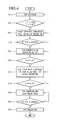
- FIG. 4 is a flowchart illustrating a control method for a refrigerator according to an exemplary embodiment of the present invention.
- this flowchart is to illustrate a content which the drawing shown in FIG. 3 means in a time series.
- control method according to the exemplary embodiment of the present invention is limited to starting while the compressor 20 stops for convenience of description (S11).
- the fridge cooling process is first performed. That is, the compressor starts to be actuated and the fridge valve is opened, and the freezer fan 241 is actuated for a set time ta (S 13).
- the freezer fan 241 is actuated for a mean while during the fridge cooling process.
- both the temperatures of the fridge and the freezer do not particularly need to increase to the set upperlimit temperatures or higher. That is, even when only any one of the temperature of the fridge and the temperature of the freezer increases to the set upperlimit temperature or higher, the compressor may be programmed to be actuated.
- the freezer fan 241 starts to be actuated and the set time ta elapsed (S 14)
- the freezer fan 241 stops to be actuated and at the same time, the fridge fan 261 starts to be actuated (S 15).
- an actuation time of the fridge fan 261 may be set differently from the exemplary embodiment.
- the fridge fan 261 is actuated to supply the cool air to the fridge 111, thereby lowering the temperature of the fridge.
- T R of the fridge 111 reaches a set temperature T a - dT (S16)
- the fridge valve is closed and the fridge fan stops to be actuated and the freezer valve is opened and the freezer fan 241 is actuated (S17). That is, the freezer cooling process starts.
- the freezer fan 241 when the freezer fan 241 is actuated to supply the cool air to the freezer 114, the temperature of the freezer 114 is lowered.
- the temperature T F of the freezer 114 reaches a set temperature Tb - dT (S18)
- the compressor 20 stops and the freezer valve is closed (S19). In this case, even though the compressor 20 stops, the freezer fan 241 is extensively actuated.
- the freezer fan 241 stops to be actuated (S21).
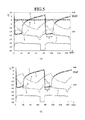
- FIG. 5 is a graph illustrating a comparison in a refrigerant state between a case in which a pump-down process is merely omitted and a case in which the control method according to the exemplary embodiment of the present invention is applied.
- a is a graph illustrating variation in temperature at the inlet of the freezer evaporator
- b is a graph illustrating variation in temperature of the outlet of the freezer evaporator
- c is a graph illustrating variation in temperature of the inlet of the fridge evaporator
- d is a graph illustrating a temperature of the outlet of the fridge evaporator
- e is a graph illustrating variation in temperature of the ice-making chamber
- f is a graph illustrating variation in input power of the compressor.
- the graph (a) of FIG. 5 illustrates a characteristic when the pump-down process is just removed from the existing cooling cycle and the graph (b) illustrates a characteristic when the control method according to the exemplary embodiment of the present invention is applied.
- Period A and period B in the graph represent a refrigerant collection time in the known case to perform the pump-down and a refrigerant collection time in a case to perform the control method according to the exemplary embodiment of the present invention, respectively.
- the refrigerant collection time may be shortened (B ⁇ A) compared with the case in which the pump-down is removed through the two graphs..
- the control method an additional pump-down process for collecting the refrigerants becomes unnecessary, and as a result, the power consumption is reduced and the evaporation latent heat remaining the freezer evaporator 24 can be effectively used. Further, the refrigerant collection time is shortened compared with the case in which the pump-down process is just omitted.
- FIG. 6 is a diagram expressing a control method for a refrigerator according to another exemplary embodiment of the present invention by an operation time and operation hours of components constituting a cooling cycle.
- the compressor 20 is actuated and at the same time, the fridge valve is opened, and the ice-making chamber is actuated.
- the fridge fan 261 is not actuated even though the fridge valve is opened in order to rapidly lower the evaporation temperature and evaporation pressure of the fridge evaporator 26 by delaying the actuation time of the fridge fan 261.
- the up-to-now process is the same as that of the previous exemplary embodiment.
- the ice-making chamber fan is actuated in the fridge cooling mode in order to cool the ice-making chamber 15 by sending the residual cool air remaining in the freezer evaporator 24 to the ice-making chamber 15 and make the evaporation temperature and evaporation pressure of the freezer evaporator 24 be maximally close to the evaporation temperature and pressure of the fridge evaporator 26 by raising the evaporation temperature and pressure of the freezer evaporator 24. Therefore, during the fridge cooling process in which the refrigerants flow to the fridge evaporator 26, the time required to collect the refrigerants remaining in the freezer evaporator 24 is shortened and the refrigerants can be easily collected without an additional pump-down process. By summarizing a difference from the previous exemplary embodiment, they are different in that the residual cool air remaining in the freezer evaporator 24 is sent to the freezer and the ice-making chamber.
- the fridge cooling mode by supplying the cool air to the ice-making chamber 15, a possibility that ice stored in the ice-making chamber will be coated decreases.
- the internal temperature of the ice-making chamber is maintained to a sub-zero temperature at all times, such that the ice is not melted and coated.
- the cool air is supplied to the ice-making chamber by extensively actuating the ice-making chamber fan, such that the compress does not need to be actuated in order to cool the ice-making chamber. Accordingly, power consumption efficiency of the refrigerator can be improved. Actually, as a verification result through the tests, the power consumption efficiency is improved by approximately 3%.
- the ice-making fan is actuated only for a set time te + tf and thereafter. stops. If the ice-making chamber fan is continuously actuated, the temperature of the supplied cool air is rather higher than the temperature of the ice-making chamber, such that the temperature of the ice-making chamber may increase.
- a time when the ice-making chamber fan is actuated in the fridge cooling mode may be a predetermined value determined through various tests and may be inputted as a predetermined time value into the control program.
- the operation time te + tf of the ice-making chamber fan may be a time value varying depending on the fridge valve opening time of the previous cycle.
- 1/2 or 1/3 of the fridge vale opening time of the previous cycle is programmed to be determined as the operation time te + tf of the ice-making fan.
- the actuation time may vary in accordance with an operation state or an operation condition.
- the actuation time of the fridge fan 261 may be a predetermined time when the set time te elapsed after the fridge valve is opened. That is, by making the actuation time of the fridge fan 261 be later than the opening time of the fridge valve, the evaporation pressure of the fridge evaporator is maximally lowered.
- the actuation time of the fridge fan 261 may be as follows in accordance with the set time te.
- the fridge fan 261 may start actuating. That is, in the fridge cooling mode, a time period that the ice-making fan and the fridge fan 261 are actuated at the same time may exist.
- the fridge fan 261 may start actuating at the time when the ice-making fan is actuated for the set time te + tf and thereafter, stops.
- the fridge fan 261 may controlled to be actuated.
- the time from the time when the fridge valve is opened to the time when the fridge fan 261 starts to be actuated may be longer than the actuation time of the ice-making chamber fan.
- the fridge valve is closed and at the same time, the freezer valve is opened to start cooling the freezer.
- the compressor 20 is continuously actuated until the temperature of the freezer 114 is lowered to the set temperature. Further, when the temperature of the freezer 114 reaches the set temperature, the freezer valve is closed and the compressor 20 stops.
- the freezer fan 241 is further actuated for a set time ti and thereafter, stops. That is, a total actuation time of the freezer fan 241 is acquired by adding the set time ti to the opening time th of the freezer valve. This is to improve cooling efficiency through maximally lowering the temperature of the freezer by supplying the residual cool air remaining in the freezer evaporator 24 to the freezer without extinction as described above.
- the extended operation time ti of the freezer fan 241 may also be a predetermined constant value determined by the tests.
- the time td may be a time value acquired from a function using as variables the temperature of the cool air introduced into the freezer evaporator 24, the temperature of the refrigerants remaining the freezer evaporator 24, and an air volume or an air velocity caused by the ice-making fan.
- a time when the temperature of the residual cool air of the freezer evaporator 24 is higher than the internal temperature of the ice-making chamber is acquired to determine the extended operation time of the freezer fan 241.
- FIG. 7 is a flowchart illustrating a control method for a refrigerator according to another exemplary embodiment of the present invention.
- this flowchart is to illustrate a content which the drawing shown in FIG. 6 means in a time series.
- control method according to the exemplary embodiment of the present invention is limited to starting while the compressor 20 stops (S31).
- the fridge cooling process is performed. That is, the compressor starts to be actuated, the fridge valve is opened, and the ice-making fan is actuated (S33).
- loads of the ice-making chamber and the freezer increase continuously during the fridge cooling process.
- by supplying the cool air to the ice-making chamber for a predetermined time during the fridge cooling chamber it is possible to prevent or minimize the ice stored in the ice-making chamber from being melted and coated.
- all the temperatures of the fridge, the freezer, and the ice-making chamber do not particularly need to increase to the set upperlimit temperatures. That is, when any one or at least two of the temperatures of the fridge, the freezer, and the ice-making chamber increase to the set upperlimit temperature or higher, the compressor may be programmed to be actuated. In addition, even when the internal temperature of the ice-making chamber is maintained within the set temperature range, the ice-making chamber may be cooled together by driving the ice-making chamber fan in the freezer cooling mode.
- the fridge fan 261 starts to be actuated (S35).
- the fridge fan 261 is actuated to supply the cool air to the fridge 111, thereby lowering the temperature of the fridge.
- the set time tf further elapsed from the actuation time of the fridge fan 261 (S36)
- the ice-making fan stops to be actuated (S37).
- the actuation time of the fridge fan and the stop time of the ice-making chamber fan are not limited to the exemplary embodiment of the present invention. That is, a period when the fridge fan and the ice-making chamber fan are actuated at the same time may be provided or not provided.
- the fridge valve is closed, the freezer valve is opened, the freezer fan 241 is actuated, and at the same time, the ice-making fan is actuated (S39). That is, the freezer and ice-making chamber cooling processes start.
- the freezer fan 241 when the freezer fan 241 is actuated to supply the cool air to the freezer 114 and the ice-making chamber 15, the temperatures of the freezer 114 and the ice-making chamber 15 are lowered.
- T 1 of the ice-making chamber reaches a set temperature T c - dT (S40)
- the ice-making chamber fan stops to be actuated (S41).
- T F of the freezer 114 reaches the set temperature Tb - dT (S42)
- the compressor 20 stops and the freezer valve is closed (S43). In this case, even though the compressor 20 stops, the freezer fan 241 is extensively actuated.
- the freezer fan 241 stops to be actuated (S45).
- the stop time of the compressor may be earlier than the actuation time of the ice-making chamber fan. The reason for that is that the cooling time of the ice-making chamber is relatively shorter than the cooling time of the freezer and whether the compressor stops is determined whether or not to satisfy the temperature of the freezer.
- FIG. 8 is a graph illustrating a comparison in a refrigerant state between a case in which a pump-down process is merely omitted and a case in which the control method according to another exemplary embodiment of the present invention is applied.
- a' is a graph illustrating variation in temperature at the inlet of the freezer evaporator
- b' is a graph illustrating variation in temperature of the outlet of the freezer evaporator
- c' is a graph illustrating variation in temperature of the inlet of the fridge evaporator
- d' is a graph illustrating a temperature of the outlet of the fridge evaporator
- e' is a graph illustrating variation in temperature of the ice-making chamber
- f' is a graph illustrating variation in input power of the compressor.
- the graph (a) of FIG. 8 illustrates a characteristic when the pump-down process is just removed from the existing cooling cycle and the graph (b) illustrates a characteristic when the control method according to another exemplary embodiment of the present invention is applied.
- the refrigerant collection time may be shortened compared with the case in which the pump-down is removed through the two graphs.
- period (A') of the graph (a) is a refrigerant collection time required when the pump-down process is deleted and period (B') of the graph (b) is a refrigerant collection time required when the control method according to another exemplary embodiment of the present invention is applied.
- the control method an additional pump-down process for collecting the refrigerants becomes unnecessary, and as a result, the power consumption is reduced and the evaporation latent heat remaining the freezer evaporator 24 can be effectively used. Further, the refrigerant collection time is shortened (B' ⁇ A') compared with the case in which the pump-down process is just omitted.
- the temperature variation graph of the ice-making chamber shown in the graph (b) it can be verified that the upperlimit temperature of the ice-making chamber is positioned at a region below the freezing temperature.
- the reason for that is that the residual cool air remaining the freezer evaporator 24 is supplied to the ice-making chamber during the fridge cooling process. Therefore, it is possible to effectively prevent ice from being coated in the ice-making chamber.
- FIG. 9 is a diagram expressing a control method for a refrigerator according to yet another exemplary embodiment of the present invention by an operation time and operation hours of components constituting a cooling cycle.
- the exemplary embodiment is substantially the same as the previous exemplary embodiments in the control method, however, they are different from each other in that the ice-making fan and the freezer fan are actuated simultaneously in the fridge cooling mode.
- the evaporation temperature and pressure of the freezer evaporator 24 further increase.
- the evaporation temperature and pressure of the freezer evaporator 26 are closer to the evaporation temperature and pressure of the fridge evaporator 26, such that the refrigerants can be more easily collected.
- the freezer fan 241 may be stop before the ice-making chamber fan stops.
- the actuation time of the freezer fan 241 and the actuation time of the ice-making chamber fan are the same as each other, however, the freezer fan 241 may stop at 1/2 or 1/3 of the actuation time of the ice-making chamber fan.
- the present invention is not limited to the exemplary embodiment, and the freezer fan may be actuated longer than the ice-making fan and may stop simultaneously.
- the stop time of the freezer fan can be appropriately selected depending on the amount of the residual cool air of the freezer evaporator 24, i.e., the amount of the refrigerants and the temperature of the refrigerants.
Landscapes
- Engineering & Computer Science (AREA)
- Chemical & Material Sciences (AREA)
- Combustion & Propulsion (AREA)
- Physics & Mathematics (AREA)
- Mechanical Engineering (AREA)
- Thermal Sciences (AREA)
- General Engineering & Computer Science (AREA)
- Devices That Are Associated With Refrigeration Equipment (AREA)
Applications Claiming Priority (2)
| Application Number | Priority Date | Filing Date | Title |
|---|---|---|---|
| KR1020100055896A KR101576687B1 (ko) | 2010-06-14 | 2010-06-14 | 냉장고의 제어 방법 |
| KR1020100055894A KR101576686B1 (ko) | 2010-06-14 | 2010-06-14 | 냉장고의 제어 방법 |
Publications (3)
| Publication Number | Publication Date |
|---|---|
| EP2395304A2 true EP2395304A2 (fr) | 2011-12-14 |
| EP2395304A3 EP2395304A3 (fr) | 2017-08-09 |
| EP2395304B1 EP2395304B1 (fr) | 2019-09-25 |
Family
ID=44532512
Family Applications (1)
| Application Number | Title | Priority Date | Filing Date |
|---|---|---|---|
| EP11004847.7A Active EP2395304B1 (fr) | 2010-06-14 | 2011-06-14 | Procédé de contrôle pour réfrigérateur |
Country Status (2)
| Country | Link |
|---|---|
| US (1) | US8640471B2 (fr) |
| EP (1) | EP2395304B1 (fr) |
Cited By (3)
| Publication number | Priority date | Publication date | Assignee | Title |
|---|---|---|---|---|
| CN108885054A (zh) * | 2016-03-24 | 2018-11-23 | Lg 电子株式会社 | 冰箱及其控制方法 |
| EP3674631A1 (fr) * | 2018-12-28 | 2020-07-01 | LG Electronics Inc. | Réfrigérateur et son procédé de commande |
| EP3964778A4 (fr) * | 2019-05-02 | 2022-06-22 | Haier Smart Home Co., Ltd. | Appareil de réfrigération et procédé pour réduire le bruit |
Families Citing this family (10)
| Publication number | Priority date | Publication date | Assignee | Title |
|---|---|---|---|---|
| KR101918224B1 (ko) * | 2012-01-31 | 2018-11-13 | 엘지전자 주식회사 | 냉장고 및 그 제상 운전 방법 |
| US9528727B2 (en) * | 2013-03-15 | 2016-12-27 | Whirlpool Corporation | Robust fixed-sequence control method and appliance for exceptional temperature stability |
| JP6406214B2 (ja) * | 2015-11-04 | 2018-10-17 | 株式会社デンソー | 収納装置 |
| CN107131700B (zh) * | 2016-02-26 | 2019-11-29 | 合肥美的电冰箱有限公司 | 冰箱 |
| KR102401782B1 (ko) * | 2017-11-02 | 2022-05-26 | 엘지전자 주식회사 | 냉장고 및 그의 제어방법 |
| KR102548045B1 (ko) * | 2018-01-26 | 2023-06-27 | 엘지전자 주식회사 | 아이스메이커 및 이를 포함하는 냉장고 |
| KR102659139B1 (ko) | 2018-09-14 | 2024-04-19 | 엘지전자 주식회사 | 냉장고 및 그의 제어방법 |
| USD916144S1 (en) | 2020-07-17 | 2021-04-13 | Guangzhou Tsunami Industrial Equipment Co., Ltd. | Refrigerator |
| US11846462B2 (en) | 2021-03-19 | 2023-12-19 | Electrolux Home Products, Inc. | Door mounted chilled component with direct cooling |
| KR20220132305A (ko) * | 2021-03-23 | 2022-09-30 | 삼성전자주식회사 | 냉장고 및 그 제어 방법 |
Citations (2)
| Publication number | Priority date | Publication date | Assignee | Title |
|---|---|---|---|---|
| KR20100055896A (ko) | 2008-11-18 | 2010-05-27 | 현대자동차주식회사 | 엔진의 냉각회로 |
| KR20100055894A (ko) | 2008-11-18 | 2010-05-27 | 현대자동차주식회사 | 연속 가변 밸브 타이밍 장치용 오일 회로 |
Family Cites Families (6)
| Publication number | Priority date | Publication date | Assignee | Title |
|---|---|---|---|---|
| US5918474A (en) * | 1996-07-30 | 1999-07-06 | Whirlpool Corporation | Fan motor on/off control system for a refrigeration appliance |
| JP3410408B2 (ja) * | 1999-11-01 | 2003-05-26 | 松下冷機株式会社 | 冷蔵庫 |
| US6679073B1 (en) * | 2003-03-14 | 2004-01-20 | General Electric Company | Refrigerator and ice maker methods and apparatus |
| US7237395B2 (en) * | 2003-12-22 | 2007-07-03 | General Electric Company | Methods and apparatus for controlling refrigerators |
| EP2097691B1 (fr) * | 2007-01-03 | 2016-06-01 | LG Electronics Inc. | Réfrigérateur de type à refroidissement séparé |
| JP4544299B2 (ja) * | 2007-12-20 | 2010-09-15 | トヨタ自動車株式会社 | ファン作動制御方法およびファン作動制御装置 |
-
2011
- 2011-06-14 US US13/159,803 patent/US8640471B2/en active Active
- 2011-06-14 EP EP11004847.7A patent/EP2395304B1/fr active Active
Patent Citations (2)
| Publication number | Priority date | Publication date | Assignee | Title |
|---|---|---|---|---|
| KR20100055896A (ko) | 2008-11-18 | 2010-05-27 | 현대자동차주식회사 | 엔진의 냉각회로 |
| KR20100055894A (ko) | 2008-11-18 | 2010-05-27 | 현대자동차주식회사 | 연속 가변 밸브 타이밍 장치용 오일 회로 |
Cited By (6)
| Publication number | Priority date | Publication date | Assignee | Title |
|---|---|---|---|---|
| CN108885054A (zh) * | 2016-03-24 | 2018-11-23 | Lg 电子株式会社 | 冰箱及其控制方法 |
| CN108885054B (zh) * | 2016-03-24 | 2020-11-13 | Lg 电子株式会社 | 冰箱及其控制方法 |
| US11067324B2 (en) | 2016-03-24 | 2021-07-20 | Lg Electronics Inc. | Refrigerator and control method therefor |
| EP3674631A1 (fr) * | 2018-12-28 | 2020-07-01 | LG Electronics Inc. | Réfrigérateur et son procédé de commande |
| US11371768B2 (en) | 2018-12-28 | 2022-06-28 | Lg Electronics Inc. | Refrigerator and method for controlling the same |
| EP3964778A4 (fr) * | 2019-05-02 | 2022-06-22 | Haier Smart Home Co., Ltd. | Appareil de réfrigération et procédé pour réduire le bruit |
Also Published As
| Publication number | Publication date |
|---|---|
| EP2395304B1 (fr) | 2019-09-25 |
| US20110302938A1 (en) | 2011-12-15 |
| EP2395304A3 (fr) | 2017-08-09 |
| US8640471B2 (en) | 2014-02-04 |
Similar Documents
| Publication | Publication Date | Title |
|---|---|---|
| EP2395304B1 (fr) | Procédé de contrôle pour réfrigérateur | |
| KR101576686B1 (ko) | 냉장고의 제어 방법 | |
| US6598410B2 (en) | Refrigerator with a plurality of parallel refrigerant passages | |
| EP2416095A2 (fr) | Réfrigérateur et son procédé de commande | |
| EP3457059B1 (fr) | Réfrigérateur et son procédé de commande | |
| US12158300B2 (en) | Refrigerator control method | |
| CN105758107B (zh) | 冰箱及其控制方法 | |
| US20130098076A1 (en) | High performance refrigerator having dual evaporator | |
| EP2889550A1 (fr) | Appareil de refroidissement pour réfrigérateur et procédé de commande de celui-ci | |
| US20130098074A1 (en) | High performance refrigerator having insulated evaporator cover | |
| KR102418143B1 (ko) | 냉장고 및 그 제어 방법 | |
| KR101576687B1 (ko) | 냉장고의 제어 방법 | |
| WO2020175831A1 (fr) | Procédé de commande de réfrigérateur | |
| WO2020175832A1 (fr) | Réfrigérateur | |
| WO2020175829A1 (fr) | Procédé de commande de réfrigérateur | |
| KR20180120975A (ko) | 냉장고 및 그 제어 방법 | |
| WO2020175830A1 (fr) | Procédé de commande de réfrigérateur | |
| EP3144609B1 (fr) | Procédé de commande pour réfrigérateur | |
| US12130079B2 (en) | Method for controlling refrigerator | |
| KR20110071169A (ko) | 냉장고의 제상 운전 제어방법 | |
| CN109764631A (zh) | 冰箱及其制冷控制方法与装置 | |
| CN109780776B (zh) | 冰箱及其控制方法 | |
| KR20100085274A (ko) | 냉장고 제어 방법 | |
| WO2020175824A1 (fr) | Procédé de commande de réfrigérateur | |
| CN1987300A (zh) | 冰箱及用于控制所述冰箱的方法 |
Legal Events
| Date | Code | Title | Description |
|---|---|---|---|
| AK | Designated contracting states |
Kind code of ref document: A2 Designated state(s): AL AT BE BG CH CY CZ DE DK EE ES FI FR GB GR HR HU IE IS IT LI LT LU LV MC MK MT NL NO PL PT RO RS SE SI SK SM TR |
|
| AX | Request for extension of the european patent |
Extension state: BA ME |
|
| PUAI | Public reference made under article 153(3) epc to a published international application that has entered the european phase |
Free format text: ORIGINAL CODE: 0009012 |
|
| PUAL | Search report despatched |
Free format text: ORIGINAL CODE: 0009013 |
|
| AK | Designated contracting states |
Kind code of ref document: A3 Designated state(s): AL AT BE BG CH CY CZ DE DK EE ES FI FR GB GR HR HU IE IS IT LI LT LU LV MC MK MT NL NO PL PT RO RS SE SI SK SM TR |
|
| AX | Request for extension of the european patent |
Extension state: BA ME |
|
| RIC1 | Information provided on ipc code assigned before grant |
Ipc: F25B 45/00 20060101ALN20170630BHEP Ipc: F25D 17/06 20060101ALI20170630BHEP Ipc: F25D 29/00 20060101AFI20170630BHEP |
|
| STAA | Information on the status of an ep patent application or granted ep patent |
Free format text: STATUS: REQUEST FOR EXAMINATION WAS MADE |
|
| 17P | Request for examination filed |
Effective date: 20171129 |
|
| RBV | Designated contracting states (corrected) |
Designated state(s): AL AT BE BG CH CY CZ DE DK EE ES FI FR GB GR HR HU IE IS IT LI LT LU LV MC MK MT NL NO PL PT RO RS SE SI SK SM TR |
|
| GRAP | Despatch of communication of intention to grant a patent |
Free format text: ORIGINAL CODE: EPIDOSNIGR1 |
|
| STAA | Information on the status of an ep patent application or granted ep patent |
Free format text: STATUS: GRANT OF PATENT IS INTENDED |
|
| INTG | Intention to grant announced |
Effective date: 20190415 |
|
| RAP1 | Party data changed (applicant data changed or rights of an application transferred) |
Owner name: LG ELECTRONICS INC. |
|
| GRAS | Grant fee paid |
Free format text: ORIGINAL CODE: EPIDOSNIGR3 |
|
| GRAA | (expected) grant |
Free format text: ORIGINAL CODE: 0009210 |
|
| STAA | Information on the status of an ep patent application or granted ep patent |
Free format text: STATUS: THE PATENT HAS BEEN GRANTED |
|
| AK | Designated contracting states |
Kind code of ref document: B1 Designated state(s): AL AT BE BG CH CY CZ DE DK EE ES FI FR GB GR HR HU IE IS IT LI LT LU LV MC MK MT NL NO PL PT RO RS SE SI SK SM TR |
|
| REG | Reference to a national code |
Ref country code: GB Ref legal event code: FG4D |
|
| REG | Reference to a national code |
Ref country code: CH Ref legal event code: EP |
|
| REG | Reference to a national code |
Ref country code: DE Ref legal event code: R096 Ref document number: 602011062260 Country of ref document: DE |
|
| REG | Reference to a national code |
Ref country code: AT Ref legal event code: REF Ref document number: 1184207 Country of ref document: AT Kind code of ref document: T Effective date: 20191015 |
|
| REG | Reference to a national code |
Ref country code: IE Ref legal event code: FG4D |
|
| REG | Reference to a national code |
Ref country code: NL Ref legal event code: MP Effective date: 20190925 |
|
| PG25 | Lapsed in a contracting state [announced via postgrant information from national office to epo] |
Ref country code: FI Free format text: LAPSE BECAUSE OF FAILURE TO SUBMIT A TRANSLATION OF THE DESCRIPTION OR TO PAY THE FEE WITHIN THE PRESCRIBED TIME-LIMIT Effective date: 20190925 Ref country code: HR Free format text: LAPSE BECAUSE OF FAILURE TO SUBMIT A TRANSLATION OF THE DESCRIPTION OR TO PAY THE FEE WITHIN THE PRESCRIBED TIME-LIMIT Effective date: 20190925 Ref country code: SE Free format text: LAPSE BECAUSE OF FAILURE TO SUBMIT A TRANSLATION OF THE DESCRIPTION OR TO PAY THE FEE WITHIN THE PRESCRIBED TIME-LIMIT Effective date: 20190925 Ref country code: BG Free format text: LAPSE BECAUSE OF FAILURE TO SUBMIT A TRANSLATION OF THE DESCRIPTION OR TO PAY THE FEE WITHIN THE PRESCRIBED TIME-LIMIT Effective date: 20191225 Ref country code: LT Free format text: LAPSE BECAUSE OF FAILURE TO SUBMIT A TRANSLATION OF THE DESCRIPTION OR TO PAY THE FEE WITHIN THE PRESCRIBED TIME-LIMIT Effective date: 20190925 Ref country code: NO Free format text: LAPSE BECAUSE OF FAILURE TO SUBMIT A TRANSLATION OF THE DESCRIPTION OR TO PAY THE FEE WITHIN THE PRESCRIBED TIME-LIMIT Effective date: 20191225 |
|
| REG | Reference to a national code |
Ref country code: LT Ref legal event code: MG4D |
|
| PG25 | Lapsed in a contracting state [announced via postgrant information from national office to epo] |
Ref country code: LV Free format text: LAPSE BECAUSE OF FAILURE TO SUBMIT A TRANSLATION OF THE DESCRIPTION OR TO PAY THE FEE WITHIN THE PRESCRIBED TIME-LIMIT Effective date: 20190925 Ref country code: GR Free format text: LAPSE BECAUSE OF FAILURE TO SUBMIT A TRANSLATION OF THE DESCRIPTION OR TO PAY THE FEE WITHIN THE PRESCRIBED TIME-LIMIT Effective date: 20191226 Ref country code: RS Free format text: LAPSE BECAUSE OF FAILURE TO SUBMIT A TRANSLATION OF THE DESCRIPTION OR TO PAY THE FEE WITHIN THE PRESCRIBED TIME-LIMIT Effective date: 20190925 |
|
| REG | Reference to a national code |
Ref country code: AT Ref legal event code: MK05 Ref document number: 1184207 Country of ref document: AT Kind code of ref document: T Effective date: 20190925 |
|
| PG25 | Lapsed in a contracting state [announced via postgrant information from national office to epo] |
Ref country code: EE Free format text: LAPSE BECAUSE OF FAILURE TO SUBMIT A TRANSLATION OF THE DESCRIPTION OR TO PAY THE FEE WITHIN THE PRESCRIBED TIME-LIMIT Effective date: 20190925 Ref country code: PT Free format text: LAPSE BECAUSE OF FAILURE TO SUBMIT A TRANSLATION OF THE DESCRIPTION OR TO PAY THE FEE WITHIN THE PRESCRIBED TIME-LIMIT Effective date: 20200127 Ref country code: NL Free format text: LAPSE BECAUSE OF FAILURE TO SUBMIT A TRANSLATION OF THE DESCRIPTION OR TO PAY THE FEE WITHIN THE PRESCRIBED TIME-LIMIT Effective date: 20190925 Ref country code: RO Free format text: LAPSE BECAUSE OF FAILURE TO SUBMIT A TRANSLATION OF THE DESCRIPTION OR TO PAY THE FEE WITHIN THE PRESCRIBED TIME-LIMIT Effective date: 20190925 Ref country code: ES Free format text: LAPSE BECAUSE OF FAILURE TO SUBMIT A TRANSLATION OF THE DESCRIPTION OR TO PAY THE FEE WITHIN THE PRESCRIBED TIME-LIMIT Effective date: 20190925 Ref country code: AT Free format text: LAPSE BECAUSE OF FAILURE TO SUBMIT A TRANSLATION OF THE DESCRIPTION OR TO PAY THE FEE WITHIN THE PRESCRIBED TIME-LIMIT Effective date: 20190925 Ref country code: PL Free format text: LAPSE BECAUSE OF FAILURE TO SUBMIT A TRANSLATION OF THE DESCRIPTION OR TO PAY THE FEE WITHIN THE PRESCRIBED TIME-LIMIT Effective date: 20190925 Ref country code: AL Free format text: LAPSE BECAUSE OF FAILURE TO SUBMIT A TRANSLATION OF THE DESCRIPTION OR TO PAY THE FEE WITHIN THE PRESCRIBED TIME-LIMIT Effective date: 20190925 |
|
| PG25 | Lapsed in a contracting state [announced via postgrant information from national office to epo] |
Ref country code: CZ Free format text: LAPSE BECAUSE OF FAILURE TO SUBMIT A TRANSLATION OF THE DESCRIPTION OR TO PAY THE FEE WITHIN THE PRESCRIBED TIME-LIMIT Effective date: 20190925 Ref country code: SK Free format text: LAPSE BECAUSE OF FAILURE TO SUBMIT A TRANSLATION OF THE DESCRIPTION OR TO PAY THE FEE WITHIN THE PRESCRIBED TIME-LIMIT Effective date: 20190925 Ref country code: IS Free format text: LAPSE BECAUSE OF FAILURE TO SUBMIT A TRANSLATION OF THE DESCRIPTION OR TO PAY THE FEE WITHIN THE PRESCRIBED TIME-LIMIT Effective date: 20200224 Ref country code: SM Free format text: LAPSE BECAUSE OF FAILURE TO SUBMIT A TRANSLATION OF THE DESCRIPTION OR TO PAY THE FEE WITHIN THE PRESCRIBED TIME-LIMIT Effective date: 20190925 |
|
| REG | Reference to a national code |
Ref country code: DE Ref legal event code: R097 Ref document number: 602011062260 Country of ref document: DE |
|
| PG2D | Information on lapse in contracting state deleted |
Ref country code: IS |
|
| PG25 | Lapsed in a contracting state [announced via postgrant information from national office to epo] |
Ref country code: DK Free format text: LAPSE BECAUSE OF FAILURE TO SUBMIT A TRANSLATION OF THE DESCRIPTION OR TO PAY THE FEE WITHIN THE PRESCRIBED TIME-LIMIT Effective date: 20190925 Ref country code: IS Free format text: LAPSE BECAUSE OF FAILURE TO SUBMIT A TRANSLATION OF THE DESCRIPTION OR TO PAY THE FEE WITHIN THE PRESCRIBED TIME-LIMIT Effective date: 20200126 |
|
| PLBE | No opposition filed within time limit |
Free format text: ORIGINAL CODE: 0009261 |
|
| STAA | Information on the status of an ep patent application or granted ep patent |
Free format text: STATUS: NO OPPOSITION FILED WITHIN TIME LIMIT |
|
| 26N | No opposition filed |
Effective date: 20200626 |
|
| PG25 | Lapsed in a contracting state [announced via postgrant information from national office to epo] |
Ref country code: SI Free format text: LAPSE BECAUSE OF FAILURE TO SUBMIT A TRANSLATION OF THE DESCRIPTION OR TO PAY THE FEE WITHIN THE PRESCRIBED TIME-LIMIT Effective date: 20190925 |
|
| PG25 | Lapsed in a contracting state [announced via postgrant information from national office to epo] |
Ref country code: MC Free format text: LAPSE BECAUSE OF FAILURE TO SUBMIT A TRANSLATION OF THE DESCRIPTION OR TO PAY THE FEE WITHIN THE PRESCRIBED TIME-LIMIT Effective date: 20190925 |
|
| REG | Reference to a national code |
Ref country code: CH Ref legal event code: PL |
|
| PG25 | Lapsed in a contracting state [announced via postgrant information from national office to epo] |
Ref country code: LU Free format text: LAPSE BECAUSE OF NON-PAYMENT OF DUE FEES Effective date: 20200614 |
|
| REG | Reference to a national code |
Ref country code: BE Ref legal event code: MM Effective date: 20200630 |
|
| PG25 | Lapsed in a contracting state [announced via postgrant information from national office to epo] |
Ref country code: IE Free format text: LAPSE BECAUSE OF NON-PAYMENT OF DUE FEES Effective date: 20200614 Ref country code: LI Free format text: LAPSE BECAUSE OF NON-PAYMENT OF DUE FEES Effective date: 20200630 Ref country code: CH Free format text: LAPSE BECAUSE OF NON-PAYMENT OF DUE FEES Effective date: 20200630 |
|
| PG25 | Lapsed in a contracting state [announced via postgrant information from national office to epo] |
Ref country code: BE Free format text: LAPSE BECAUSE OF NON-PAYMENT OF DUE FEES Effective date: 20200630 |
|
| PG25 | Lapsed in a contracting state [announced via postgrant information from national office to epo] |
Ref country code: TR Free format text: LAPSE BECAUSE OF FAILURE TO SUBMIT A TRANSLATION OF THE DESCRIPTION OR TO PAY THE FEE WITHIN THE PRESCRIBED TIME-LIMIT Effective date: 20190925 Ref country code: MT Free format text: LAPSE BECAUSE OF FAILURE TO SUBMIT A TRANSLATION OF THE DESCRIPTION OR TO PAY THE FEE WITHIN THE PRESCRIBED TIME-LIMIT Effective date: 20190925 Ref country code: CY Free format text: LAPSE BECAUSE OF FAILURE TO SUBMIT A TRANSLATION OF THE DESCRIPTION OR TO PAY THE FEE WITHIN THE PRESCRIBED TIME-LIMIT Effective date: 20190925 |
|
| PG25 | Lapsed in a contracting state [announced via postgrant information from national office to epo] |
Ref country code: MK Free format text: LAPSE BECAUSE OF FAILURE TO SUBMIT A TRANSLATION OF THE DESCRIPTION OR TO PAY THE FEE WITHIN THE PRESCRIBED TIME-LIMIT Effective date: 20190925 |
|
| P01 | Opt-out of the competence of the unified patent court (upc) registered |
Effective date: 20230523 |
|
| PGFP | Annual fee paid to national office [announced via postgrant information from national office to epo] |
Ref country code: DE Payment date: 20250508 Year of fee payment: 15 |
|
| PGFP | Annual fee paid to national office [announced via postgrant information from national office to epo] |
Ref country code: GB Payment date: 20250508 Year of fee payment: 15 |
|
| PGFP | Annual fee paid to national office [announced via postgrant information from national office to epo] |
Ref country code: IT Payment date: 20250512 Year of fee payment: 15 |
|
| PGFP | Annual fee paid to national office [announced via postgrant information from national office to epo] |
Ref country code: FR Payment date: 20250513 Year of fee payment: 15 |