EP2396523B1 - Catalyseur pour le traitement des gaz d'echappement d'un moteur a combustion et procede d'obtention d'un tel catalyseur - Google Patents
Catalyseur pour le traitement des gaz d'echappement d'un moteur a combustion et procede d'obtention d'un tel catalyseur Download PDFInfo
- Publication number
- EP2396523B1 EP2396523B1 EP10707583A EP10707583A EP2396523B1 EP 2396523 B1 EP2396523 B1 EP 2396523B1 EP 10707583 A EP10707583 A EP 10707583A EP 10707583 A EP10707583 A EP 10707583A EP 2396523 B1 EP2396523 B1 EP 2396523B1
- Authority
- EP
- European Patent Office
- Prior art keywords
- active phase
- catalyst
- content
- substrate
- low
- Prior art date
- Legal status (The legal status is an assumption and is not a legal conclusion. Google has not performed a legal analysis and makes no representation as to the accuracy of the status listed.)
- Active
Links
Images
Classifications
-
- B—PERFORMING OPERATIONS; TRANSPORTING
- B01—PHYSICAL OR CHEMICAL PROCESSES OR APPARATUS IN GENERAL
- B01J—CHEMICAL OR PHYSICAL PROCESSES, e.g. CATALYSIS OR COLLOID CHEMISTRY; THEIR RELEVANT APPARATUS
- B01J35/00—Catalysts, in general, characterised by their form or physical properties
- B01J35/50—Catalysts, in general, characterised by their form or physical properties characterised by their shape or configuration
- B01J35/56—Foraminous structures having flow-through passages or channels, e.g. grids or three-dimensional [3D] monoliths
-
- F—MECHANICAL ENGINEERING; LIGHTING; HEATING; WEAPONS; BLASTING
- F01—MACHINES OR ENGINES IN GENERAL; ENGINE PLANTS IN GENERAL; STEAM ENGINES
- F01N—GAS-FLOW SILENCERS OR EXHAUST APPARATUS FOR MACHINES OR ENGINES IN GENERAL; GAS-FLOW SILENCERS OR EXHAUST APPARATUS FOR INTERNAL-COMBUSTION ENGINES
- F01N3/00—Exhaust or silencing apparatus having means for purifying, rendering innocuous, or otherwise treating exhaust
- F01N3/08—Exhaust or silencing apparatus having means for purifying, rendering innocuous, or otherwise treating exhaust for rendering innocuous
- F01N3/10—Exhaust or silencing apparatus having means for purifying, rendering innocuous, or otherwise treating exhaust for rendering innocuous by thermal or catalytic conversion of noxious components of exhaust
- F01N3/24—Exhaust or silencing apparatus having means for purifying, rendering innocuous, or otherwise treating exhaust for rendering innocuous by thermal or catalytic conversion of noxious components of exhaust characterised by constructional aspects of converting apparatus
- F01N3/28—Construction of catalytic reactors
- F01N3/2882—Catalytic reactors combined or associated with other devices, e.g. exhaust silencers or other exhaust purification devices
-
- B—PERFORMING OPERATIONS; TRANSPORTING
- B01—PHYSICAL OR CHEMICAL PROCESSES OR APPARATUS IN GENERAL
- B01D—SEPARATION
- B01D53/00—Separation of gases or vapours; Recovering vapours of volatile solvents from gases; Chemical or biological purification of waste gases, e.g. engine exhaust gases, smoke, fumes, flue gases, aerosols
- B01D53/34—Chemical or biological purification of waste gases
- B01D53/92—Chemical or biological purification of waste gases of engine exhaust gases
- B01D53/94—Chemical or biological purification of waste gases of engine exhaust gases by catalytic processes
- B01D53/944—Simultaneously removing carbon monoxide, hydrocarbons or carbon making use of oxidation catalysts
-
- B—PERFORMING OPERATIONS; TRANSPORTING
- B01—PHYSICAL OR CHEMICAL PROCESSES OR APPARATUS IN GENERAL
- B01J—CHEMICAL OR PHYSICAL PROCESSES, e.g. CATALYSIS OR COLLOID CHEMISTRY; THEIR RELEVANT APPARATUS
- B01J23/00—Catalysts comprising metals or metal oxides or hydroxides, not provided for in group B01J21/00
- B01J23/38—Catalysts comprising metals or metal oxides or hydroxides, not provided for in group B01J21/00 of noble metals
- B01J23/40—Catalysts comprising metals or metal oxides or hydroxides, not provided for in group B01J21/00 of noble metals of the platinum group metals
-
- B—PERFORMING OPERATIONS; TRANSPORTING
- B01—PHYSICAL OR CHEMICAL PROCESSES OR APPARATUS IN GENERAL
- B01J—CHEMICAL OR PHYSICAL PROCESSES, e.g. CATALYSIS OR COLLOID CHEMISTRY; THEIR RELEVANT APPARATUS
- B01J35/00—Catalysts, in general, characterised by their form or physical properties
- B01J35/19—Catalysts containing parts with different compositions
-
- B—PERFORMING OPERATIONS; TRANSPORTING
- B01—PHYSICAL OR CHEMICAL PROCESSES OR APPARATUS IN GENERAL
- B01J—CHEMICAL OR PHYSICAL PROCESSES, e.g. CATALYSIS OR COLLOID CHEMISTRY; THEIR RELEVANT APPARATUS
- B01J37/00—Processes, in general, for preparing catalysts; Processes, in general, for activation of catalysts
- B01J37/02—Impregnation, coating or precipitation
- B01J37/0201—Impregnation
-
- F—MECHANICAL ENGINEERING; LIGHTING; HEATING; WEAPONS; BLASTING
- F01—MACHINES OR ENGINES IN GENERAL; ENGINE PLANTS IN GENERAL; STEAM ENGINES
- F01N—GAS-FLOW SILENCERS OR EXHAUST APPARATUS FOR MACHINES OR ENGINES IN GENERAL; GAS-FLOW SILENCERS OR EXHAUST APPARATUS FOR INTERNAL-COMBUSTION ENGINES
- F01N3/00—Exhaust or silencing apparatus having means for purifying, rendering innocuous, or otherwise treating exhaust
- F01N3/08—Exhaust or silencing apparatus having means for purifying, rendering innocuous, or otherwise treating exhaust for rendering innocuous
- F01N3/10—Exhaust or silencing apparatus having means for purifying, rendering innocuous, or otherwise treating exhaust for rendering innocuous by thermal or catalytic conversion of noxious components of exhaust
- F01N3/18—Exhaust or silencing apparatus having means for purifying, rendering innocuous, or otherwise treating exhaust for rendering innocuous by thermal or catalytic conversion of noxious components of exhaust characterised by methods of operation; Control
- F01N3/20—Exhaust or silencing apparatus having means for purifying, rendering innocuous, or otherwise treating exhaust for rendering innocuous by thermal or catalytic conversion of noxious components of exhaust characterised by methods of operation; Control specially adapted for catalytic conversion
- F01N3/2006—Periodically heating or cooling catalytic reactors, e.g. at cold starting or overheating
-
- F—MECHANICAL ENGINEERING; LIGHTING; HEATING; WEAPONS; BLASTING
- F01—MACHINES OR ENGINES IN GENERAL; ENGINE PLANTS IN GENERAL; STEAM ENGINES
- F01N—GAS-FLOW SILENCERS OR EXHAUST APPARATUS FOR MACHINES OR ENGINES IN GENERAL; GAS-FLOW SILENCERS OR EXHAUST APPARATUS FOR INTERNAL-COMBUSTION ENGINES
- F01N3/00—Exhaust or silencing apparatus having means for purifying, rendering innocuous, or otherwise treating exhaust
- F01N3/08—Exhaust or silencing apparatus having means for purifying, rendering innocuous, or otherwise treating exhaust for rendering innocuous
- F01N3/10—Exhaust or silencing apparatus having means for purifying, rendering innocuous, or otherwise treating exhaust for rendering innocuous by thermal or catalytic conversion of noxious components of exhaust
- F01N3/24—Exhaust or silencing apparatus having means for purifying, rendering innocuous, or otherwise treating exhaust for rendering innocuous by thermal or catalytic conversion of noxious components of exhaust characterised by constructional aspects of converting apparatus
- F01N3/28—Construction of catalytic reactors
- F01N3/2803—Construction of catalytic reactors characterised by structure, by material or by manufacturing of catalyst support
-
- B—PERFORMING OPERATIONS; TRANSPORTING
- B01—PHYSICAL OR CHEMICAL PROCESSES OR APPARATUS IN GENERAL
- B01D—SEPARATION
- B01D2255/00—Catalysts
- B01D2255/10—Noble metals or compounds thereof
- B01D2255/102—Platinum group metals
-
- B—PERFORMING OPERATIONS; TRANSPORTING
- B01—PHYSICAL OR CHEMICAL PROCESSES OR APPARATUS IN GENERAL
- B01D—SEPARATION
- B01D2255/00—Catalysts
- B01D2255/90—Physical characteristics of catalysts
-
- B—PERFORMING OPERATIONS; TRANSPORTING
- B01—PHYSICAL OR CHEMICAL PROCESSES OR APPARATUS IN GENERAL
- B01D—SEPARATION
- B01D2257/00—Components to be removed
- B01D2257/30—Sulfur compounds
- B01D2257/302—Sulfur oxides
-
- B—PERFORMING OPERATIONS; TRANSPORTING
- B01—PHYSICAL OR CHEMICAL PROCESSES OR APPARATUS IN GENERAL
- B01D—SEPARATION
- B01D2257/00—Components to be removed
- B01D2257/60—Heavy metals or heavy metal compounds
-
- B—PERFORMING OPERATIONS; TRANSPORTING
- B01—PHYSICAL OR CHEMICAL PROCESSES OR APPARATUS IN GENERAL
- B01D—SEPARATION
- B01D53/00—Separation of gases or vapours; Recovering vapours of volatile solvents from gases; Chemical or biological purification of waste gases, e.g. engine exhaust gases, smoke, fumes, flue gases, aerosols
- B01D53/34—Chemical or biological purification of waste gases
- B01D53/92—Chemical or biological purification of waste gases of engine exhaust gases
- B01D53/94—Chemical or biological purification of waste gases of engine exhaust gases by catalytic processes
- B01D53/9459—Removing one or more of nitrogen oxides, carbon monoxide, or hydrocarbons by multiple successive catalytic functions; systems with more than one different function, e.g. zone coated catalysts
- B01D53/9477—Removing one or more of nitrogen oxides, carbon monoxide, or hydrocarbons by multiple successive catalytic functions; systems with more than one different function, e.g. zone coated catalysts with catalysts positioned on separate bricks, e.g. exhaust systems
-
- F—MECHANICAL ENGINEERING; LIGHTING; HEATING; WEAPONS; BLASTING
- F01—MACHINES OR ENGINES IN GENERAL; ENGINE PLANTS IN GENERAL; STEAM ENGINES
- F01N—GAS-FLOW SILENCERS OR EXHAUST APPARATUS FOR MACHINES OR ENGINES IN GENERAL; GAS-FLOW SILENCERS OR EXHAUST APPARATUS FOR INTERNAL-COMBUSTION ENGINES
- F01N2260/00—Exhaust treating devices having provisions not otherwise provided for
- F01N2260/24—Exhaust treating devices having provisions not otherwise provided for for identifying exhaust parts or devices, e.g. by labels, stickers or directly printing
-
- F—MECHANICAL ENGINEERING; LIGHTING; HEATING; WEAPONS; BLASTING
- F01—MACHINES OR ENGINES IN GENERAL; ENGINE PLANTS IN GENERAL; STEAM ENGINES
- F01N—GAS-FLOW SILENCERS OR EXHAUST APPARATUS FOR MACHINES OR ENGINES IN GENERAL; GAS-FLOW SILENCERS OR EXHAUST APPARATUS FOR INTERNAL-COMBUSTION ENGINES
- F01N2510/00—Surface coverings
- F01N2510/06—Surface coverings for exhaust purification, e.g. catalytic reaction
- F01N2510/068—Surface coverings for exhaust purification, e.g. catalytic reaction characterised by the distribution of the catalytic coatings
- F01N2510/0682—Surface coverings for exhaust purification, e.g. catalytic reaction characterised by the distribution of the catalytic coatings having a discontinuous, uneven or partially overlapping coating of catalytic material, e.g. higher amount of material upstream than downstream or vice versa
-
- F—MECHANICAL ENGINEERING; LIGHTING; HEATING; WEAPONS; BLASTING
- F01—MACHINES OR ENGINES IN GENERAL; ENGINE PLANTS IN GENERAL; STEAM ENGINES
- F01N—GAS-FLOW SILENCERS OR EXHAUST APPARATUS FOR MACHINES OR ENGINES IN GENERAL; GAS-FLOW SILENCERS OR EXHAUST APPARATUS FOR INTERNAL-COMBUSTION ENGINES
- F01N2570/00—Exhaust treating apparatus eliminating, absorbing or adsorbing specific elements or compounds
- F01N2570/04—Sulfur or sulfur oxides
-
- F—MECHANICAL ENGINEERING; LIGHTING; HEATING; WEAPONS; BLASTING
- F01—MACHINES OR ENGINES IN GENERAL; ENGINE PLANTS IN GENERAL; STEAM ENGINES
- F01N—GAS-FLOW SILENCERS OR EXHAUST APPARATUS FOR MACHINES OR ENGINES IN GENERAL; GAS-FLOW SILENCERS OR EXHAUST APPARATUS FOR INTERNAL-COMBUSTION ENGINES
- F01N2570/00—Exhaust treating apparatus eliminating, absorbing or adsorbing specific elements or compounds
- F01N2570/06—Zinc
-
- F—MECHANICAL ENGINEERING; LIGHTING; HEATING; WEAPONS; BLASTING
- F01—MACHINES OR ENGINES IN GENERAL; ENGINE PLANTS IN GENERAL; STEAM ENGINES
- F01N—GAS-FLOW SILENCERS OR EXHAUST APPARATUS FOR MACHINES OR ENGINES IN GENERAL; GAS-FLOW SILENCERS OR EXHAUST APPARATUS FOR INTERNAL-COMBUSTION ENGINES
- F01N2570/00—Exhaust treating apparatus eliminating, absorbing or adsorbing specific elements or compounds
- F01N2570/08—Phosphorus
-
- Y—GENERAL TAGGING OF NEW TECHNOLOGICAL DEVELOPMENTS; GENERAL TAGGING OF CROSS-SECTIONAL TECHNOLOGIES SPANNING OVER SEVERAL SECTIONS OF THE IPC; TECHNICAL SUBJECTS COVERED BY FORMER USPC CROSS-REFERENCE ART COLLECTIONS [XRACs] AND DIGESTS
- Y02—TECHNOLOGIES OR APPLICATIONS FOR MITIGATION OR ADAPTATION AGAINST CLIMATE CHANGE
- Y02A—TECHNOLOGIES FOR ADAPTATION TO CLIMATE CHANGE
- Y02A50/00—TECHNOLOGIES FOR ADAPTATION TO CLIMATE CHANGE in human health protection, e.g. against extreme weather
- Y02A50/20—Air quality improvement or preservation, e.g. vehicle emission control or emission reduction by using catalytic converters
-
- Y—GENERAL TAGGING OF NEW TECHNOLOGICAL DEVELOPMENTS; GENERAL TAGGING OF CROSS-SECTIONAL TECHNOLOGIES SPANNING OVER SEVERAL SECTIONS OF THE IPC; TECHNICAL SUBJECTS COVERED BY FORMER USPC CROSS-REFERENCE ART COLLECTIONS [XRACs] AND DIGESTS
- Y02—TECHNOLOGIES OR APPLICATIONS FOR MITIGATION OR ADAPTATION AGAINST CLIMATE CHANGE
- Y02T—CLIMATE CHANGE MITIGATION TECHNOLOGIES RELATED TO TRANSPORTATION
- Y02T10/00—Road transport of goods or passengers
- Y02T10/10—Internal combustion engine [ICE] based vehicles
- Y02T10/12—Improving ICE efficiencies
Definitions
- the invention relates to the field of the pollution control of the exhaust gases of a combustion engine.
- a catalyst and in particular a catalyst intended for the depollution of the exhaust gases of an internal combustion engine is generally composed of a substrate, which may be a ceramic monolith, coated with a catalytic active phase which can be referred to by the Anglo-Saxon term "washcoat".
- This active phase has, before drying (calcination), a more or less pasty or liquid form that is designated by the English name "slurry". According to the French terminology, we will speak of active phase as equivalent of the term “washcoat” and active phase in liquid solution as equivalent of the term "slurry".
- it is conventionally designated by entry of the catalyst or substrate the face through which enter the exhaust gas to be treated, and outlet the face by which these gases emerge once treated by the catalyst.
- zoned catalyst technologies that is to say catalysts offering zones with specific active phase compositions. But this type of technology is expensive to produce and is generally used to increase the efficiency of the catalyst through the addition of a greater amount of precious metals at the input of the monolith. If “zoning” can allow to retain a significant activity on a spent catalyst (its efficiency to nine being higher), it does not prevent the poisoning phenomenon of the catalyst. On the contrary, poisoning in the case of a zoned catalyst can have very unfortunate consequences since the The conversion potential of this type of catalytic bread is almost exclusively input where the poisons are deposited preferentially. Catalysts are known with a zone of low active phase content at the inlet of the substrate in a document US4134733A .
- the invention aims to solve the problem of poisoning catalysts by providing a catalyst particularly resistant to this phenomenon but still having good efficiency, as well as the process for obtaining such a catalyst.
- the invention therefore relates to a catalyst for the treatment of the exhaust gases of a combustion engine, comprising a monolithic substrate comprising channels covered with a catalytic active phase unequally distributed in said channels, exhibiting a low active content zone over a length of 1.5 to 3 cm at the inlet of the substrate, said low active phase zone having an active phase content of at most 10% of the average active phase content catalyst outside said low-grade zone, and characterized in that it has, immediately after the zone of low active phase content and on a second length of between 0.5 and 1.5 cm, a zone of strong active phase content having an active phase content at least 10% greater than the average active phase content of the catalyst, outside said low active content and high ph content zones; active ase.
- the poisoning related to the engine oil elements or the impurities of the fuel essentially concerns the first centimeters of the catalyst, taken in the direction of flow of the gas stream that it processes.
- the idea developed in the invention is to minimize the amount of precious metals deposited in a given zone at the catalyst inlet, or even to remove it.
- the first centimeters of the catalyst are then strongly poisoned during the use of the catalyst.
- these first centimeters have a low cost of production, because of the low content (or absence) of precious metals in this area.
- by proposing a zone of high content in the active phase, immediately after the low-grade zone there is thus a more efficient system during the catalyst initiation phase (temperature rise) the priming zone substrate having a small surplus of precious metals.
- the invention also relates to a process for the particular impregnation of the catalyst substrate, in order to reduce the amount of precious metals entering the catalyst.
- the process thus developed essentially consists of a modification of the known method of "slurry thrust" in the channels of the substrate.
- This process proceeds as follows: the impregnation of an active phase layer is done in one go by pushing the active phase in liquid solution in the channels of the monolith using a piston device. Once the active phase has coated the entire length of the inner walls of the channels of the monolith and reappears at the other end of the substrate, a suction system sucks excess slurry at the substrate side by which the active phase in liquid solution is introduced, to avoid leaving on the outside of the channels and degrade the quality of the substrate. If the process developed in the invention applies in particular to the method of pushing slurry, it is also applicable to other similar methods, in which is penetrated by any means the active phase in liquid solution by one end catalyst substrate.
- the invention therefore relates to a process for obtaining a catalyst according to the invention, in which a homogeneous impregnation of the substrate is carried out by an active phase in liquid solution, and then the active phase in liquid solution is aspirated at the level of the outlet of the channels of the substrate, in order to remove the excess of active phase in solution, characterized in that a suction is applied such that it allows obtaining a zone of low content of active phase input of the substrate, having an active phase content of at most 10% of the average active phase content of the catalyst, outside said low-grade zone.
- the purpose of the aspiration is therefore not only to remove the excess of active phase in liquid solution, as is conventionally practiced in slurry impregnation impregnation processes known in the state of the art. technique, but to allow the formation of a zone of low content in the active phase.
- the depression exerted will be greater than what can be generally applied.
- the homogeneous impregnation of the substrate is carried out during a push-impregnation phase of the active phase, during which an active phase in liquid solution is pushed inside the channels of the monolithic substrate until that the active phase uniformly covers the channels of the substrate over their entire length.
- This solution is simple to implement, especially since only the means for achieving the successive suction at this phase are to be adapted.
- This suction according to the invention offers an advantage: it generates a washcoat surplus a few centimeters after the entry of the bread, which increases the amount of precious metals in this area, thus creating an area of high impregnation content.
- this area located shortly after the entry of the catalyst, the heat exchange and the exchange of materials are much more efficient than in the rest of the catalyst.
- these catalytic systems begin first. In other words, it is in this zone that the catalytic reactions of pollutant conversion start in the first place.
- the active phase in liquid solution aspirated as part of the process according to the invention is recovered for subsequent reuse.
- One of the objectives of the intention being not to use precious metals that would be only inefficient for the conversion of pollutants in order to reduce the cost of obtaining catalysts, it is obviously important to take advantage of the invention. to provide a means of recovery mechanically removed washcoat to reuse the active phase in liquid solution or at least recycle precious metals.
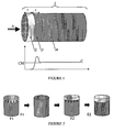
- FIG 1 schematically shows the distribution of the catalytic active phase in a catalyst according to the preferred embodiment of the invention, by delimiting zones of different concentrations on the schematic representation of a catalytic bread 1 (upper diagram of the figure 1 ), and on a graph opposite catalytic bread 1 (lower diagram of the figure 1 ).
- this vacuum is adapted to multiple parameters (quantity and viscosity of the slurry, geometry of the channels, cell density of the substrate, etc.) in order to obtain a zone of low content in the active phase 2 containing at least plus 10% of the average active phase content of the catalyst outside the zone of low active phase content 2, over a length of between 1.5 and 3 cm. It may result from this process an area of high content of active phase 3, not shown in this figure, immediately after the low-content zone 2.
- pro-octane metal additives such as Methylcyclopentadienyl Manganese Tricarbonyl (MMT) or ferrocene in some countries creates additional risks of catalyst poisoning and still justifies the use of a catalyst defined as such. than in the invention.
- MMT Methylcyclopentadienyl Manganese Tricarbonyl
Landscapes
- Chemical & Material Sciences (AREA)
- Engineering & Computer Science (AREA)
- Chemical Kinetics & Catalysis (AREA)
- Materials Engineering (AREA)
- Organic Chemistry (AREA)
- Combustion & Propulsion (AREA)
- Health & Medical Sciences (AREA)
- Mechanical Engineering (AREA)
- Toxicology (AREA)
- General Engineering & Computer Science (AREA)
- Biomedical Technology (AREA)
- Environmental & Geological Engineering (AREA)
- Analytical Chemistry (AREA)
- General Chemical & Material Sciences (AREA)
- Oil, Petroleum & Natural Gas (AREA)
- Catalysts (AREA)
- Exhaust Gas After Treatment (AREA)
- Exhaust Gas Treatment By Means Of Catalyst (AREA)
Description
- L'invention porte sur le domaine de la dépollution des gaz d'échappement d'un moteur à combustion.
- Les normes concernant les émissions des moteurs à combustion, notamment pour les automobiles, sont de plus en plus sévères. Non seulement les niveaux en polluants à ne pas dépasser sont de plus en plus bas mais la durabilité réglementaire des dispositifs de dépollution augmente pour les normes à venir, et passe notamment de 100 000 km à 160 000 km dans le cas de la norme Euro5. On emploie pour le traitement des gaz d'échappement des moteur à combustion des catalyseurs, qui sont des dispositifs onéreux, en particulier lorsqu'on cherche à obtenir une efficacité de conversion des polluants élevée. En effet, un catalyseur est constitué d'un substrat généralement recouvert d'une phase active à base de métaux précieux, pouvant être notamment du platine (Pt), du palladium (Pd), ou encore du rhodium (Rh), dont le coût est particulièrement élevé.
- Les catalyseurs perdent de leur efficacité au cours de leur fonctionnement sur véhicule. Une des principales causes de dégradation des catalyseurs est leur vieillissement thermique lié au niveau élevé des températures subies. Hormis ce vieillissement thermique, d'autres phénomènes comme l'empoisonnement réduisent leur efficacité à convertir les polluants. Si le facteur de détérioration premier des catalyseurs automobiles reste la température et les gradients de température subis par le système de dépollution, d'autres paramètres comme l'empoisonnement lié aux éléments de l'huile de lubrification du moteur et aux impuretés des carburants peuvent significativement dégrader l'efficacité d'un catalyseur. En effet, par exemple pour une application automobile classique, le passage d'huile de lubrification dans les chambres de combustion du moteur s'accroît irrémédiablement avec l'utilisation du véhicule, et devient notamment prépondérante au-delà de 100 000 km. Des éléments de l'huile tout comme les impuretés du carburant se retrouvent donc dans les gaz d'échappement du moteur et peuvent se déposer dans les systèmes catalytiques, ce qui entraine deux phénomènes distincts néfastes :
- ● Un empoisonnement physique : il s'agit du bouchage de la porosité du catalyseur ou formation par exemple d'un vernis de pyrophosphate de zinc qui empêche les molécules de polluants de diffuser au travers de la phase active et ainsi d'atteindre les sites actifs.
- ● Un empoisonnement chimique : c'est l'occupation plus ou moins réversible des sites actifs du catalyseur par des molécules comme le phosphore ou le soufre qui empêcheront ensuite les polluants d'être convertis.
- Cet empoisonnement aura donc pour conséquence de dégrader l'efficacité des catalyseurs, sachant en outre que cet effet est cumulatif et en partie irréversible.
- Aujourd'hui, il existe des solutions pour limiter le risque d'empoisonnement du catalyseur. On peut citer par exemple les « pièges à SOx » qui servent à stocker les sulfates (le soufre du carburant et de l'huile). Mais il n'est que peu (voire pas) utilisé dans le domaine des véhicules particuliers. En outre, un tel dispositif ne piège pas tous les poisons (il est dédié au piégeage des sulfates).
- On notera qu'un catalyseur, et en particulier un catalyseur destiné à la dépollution des gaz d'échappement d'un moteur à combustion interne est généralement composé d'un substrat, pouvant être un monolithe en céramique, enduit d'une phase active catalytique que l'on peut désigner par le terme anglo-saxon de « washcoat ». Cette phase active a, avant séchage (calcination), une forme plus ou moins pâteuse ou liquide que l'on désigne par l'appellation anglophone « slurry ». Suivant la terminologie française, on parlera de phase active comme équivalent du terme « washcoat » et de phase active en solution liquide comme équivalent du terme «slurry ». Par ailleurs, on désigne conventionnellement par entrée du catalyseur ou du substrat la face par laquelle pénètrent les gaz d'échappement à traiter, et par sortie la face par laquelle ces gaz ressortent une fois traités par le catalyseur.
- On connait par ailleurs des technologies de catalyseurs dites « zonées », c'est-à-dire des catalyseurs offrant des zones avec des compositions de phase active spécifiques. Mais ce type de technologies est coûteux à produire et est généralement utilisé pour accroitre l'efficacité du catalyseur grâce à l'ajout d'une plus grande quantité de métaux précieux en entrée du monolithe. Si le « zonage » peut permettre de conserver une activité importante sur un catalyseur usé (son efficacité à neuf étant supérieure), il n'empêche en rien le phénomène d'empoisonnement du catalyseur. Bien au contraire, l'empoisonnement dans le cas d'un catalyseur zoné peut avoir des conséquences très fâcheuses puisque le potentiel de conversion de ce type de pain catalytique se situe quasiment exclusivement en entrée là où les poisons se déposent préférentiellement.
On connait des catalyseurs avec une zone de faible teneur en phase active en entrée du substrat dans documentUS4134733A . - On connait enfin dans certaines applications automobiles, et plus particulièrement au niveau des stratégies de calibration moteur, des solutions coûteuses qui permettent de compenser l'impact de l'empoisonnement des catalyseurs, voire de le limiter s'il s'agit d'un empoisonnement au soufre. En effet, cet empoisonnement étant en partie réversible, il est possible en augmentant la température du catalyseur de désorber la plupart des molécules de soufre et ainsi de retrouver des performances catalytiques satisfaisantes. Cependant, si un empoisonnement du catalyseur par le soufre est grandement réversible, ce n'est pas le cas de tous les types d'empoisonnement. En particulier, le Phosphore et le Zinc peuvent former un vernis de pyrophosphate de zinc qui empêche la diffusion des espèces polluantes vers les sites actifs (métaux précieux) et qui dégrade donc fortement l'efficacité du système.
- L'invention vise à résoudre le problème de l'empoisonnement des catalyseurs en proposant un catalyseur particulièrement résistant à ce phénomène mais présentant néanmoins une bonne efficacité, ainsi que le procédé d'obtention d'un tel catalyseur.
- Plus précisément, l'invention porte donc sur catalyseur pour le traitement des gaz d'échappement d'un moteur à combustion, comportant un substrat monolithique comportant des canaux recouverts d'une phase active catalytique répartie de manière non homogène dans lesdits canaux, présentant une zone de faible teneur en phase active sur une longueur comprise entre 1,5 et 3 cm en entrée du substrat, ladite zone de faible teneur en phase active présentant une teneur en phase active d'au plus 10% de la teneur moyenne en phase active du catalyseur en dehors de ladite zone de faible teneur, et caractérisé en ce qu'il présente, immédiatement après la zone de faible teneur en phase active et sur une seconde longueur comprise entre 0,5 et 1,5 cm, une zone de forte teneur en phase active présentant une teneur en phase active supérieure d'au moins 10% à la teneur moyenne en phase active du catalyseur, en dehors desdites zones de faible teneur en phase active et de forte teneur en phase active. L'inventeur a constaté que l'empoisonnement lié aux éléments d'huile moteur ou aux impuretés du carburant concerne essentiellement les premiers centimètres du catalyseur, pris selon le sens d'écoulement du flux gazeux qu'il traite. Ainsi, l'idée développée dans l'invention est-elle de réduire au maximum la quantité de métaux précieux déposés dans une zone déterminée à l'entrée du catalyseur, voire de la supprimer. Les premiers centimètres du catalyseur se voient alors fortement empoisonnés lors de l'utilisation du catalyseur. Cependant, ces premier centimètres ont un coût d'obtention faible, du fait de la faible teneur (ou de l'absence) de métaux précieux dans cette zone. En outre, en proposant une zone de forte teneur en phase active, immédiatement après la zone de faible teneur, on dispose ainsi d'un système plus efficace lors de la phase d'amorçage du catalyseur (montée en température) la zone d'amorçage du substrat présentant un petit surplus de métaux précieux.
- De préférence, le catalyseur comporte un moyen détrompeur, permettant l'identification du côté du substrat présentant une zone de faible teneur en phase active, ou empêchant un montage inversé du catalyseur. Ce moyen peut être de tout type, visuel ou mécanique, et consister par exemple en une flèche indiquant le sens de l'écoulement du flux de gaz ou tout autre repère coloré notifié sur l'un des côtés du substrat,.
- Pour l'obtention d'un tel catalyseur, l'invention porte également sur un procédé d'imprégnation particulier du substrat du catalyseur, afin de réduire la quantité de métaux précieux en entrée du catalyseur.
- Le procédé ainsi développé consiste donc essentiellement en une modification du procédé connu de « poussée du slurry» dans les canaux du substrat. Ce procédé se déroule de la manière suivante : l'imprégnation d'une couche de phase active se fait en une seule fois par poussée de la phase active en solution liquide dans les canaux du monolithe à l'aide d'un dispositif à piston. Une fois que la phase active a enduit toute la longueur des parois internes des canaux du monolithe et qu'elle réapparaît à l'autre extrémité du substrat, un système d'aspiration aspire l'excédent de slurry, au niveau de la face du substrat par laquelle on a introduit la phase active en solution liquide, pour éviter d'en laisser sur l'extérieur des canaux et de dégrader la qualité du substrat. Si le procédé développé dans l'invention s'applique en particulier à la méthode par poussée du slurry, il est également applicable à d'autres méthodes analogues, dans lesquelles on fait pénétrer par un moyen quelconque la phase active en solution liquide par une extrémité du substrat du catalyseur.
- L'invention porte donc sur un procédé d'obtention d'un catalyseur selon l'invention, dans lequel on effectue une imprégnation homogène du substrat par une phase active en solution liquide, puis on aspire une part la phase active en solution liquide au niveau de la sortie des canaux du substrat, afin d'ôter l'excédent de phase active en solution, caractérisé en ce qu'on applique une aspiration telle qu'elle permette l'obtention d'une zone de faible teneur en phase active en entrée du substrat, présentant une teneur en phase active d'au plus 10% de la teneur moyenne en phase active du catalyseur en dehors de ladite zone de faible teneur. L'objectif de l'aspiration n'est donc pas uniquement d'ôter l'excédent de phase active en solution liquide, tel qu'on le pratique classiquement dans les procédés d'imprégnation par poussée du slurry connus dans l'état de la technique, mais de permettre la formation d'une zone de faible teneur en phase active. La dépression exercée sera donc supérieure à ce qui peut être généralement appliqué.
- De préférence, on effectue l'imprégnation homogène du substrat lors d'une phase d'imprégnation par poussée de la phase active, lors de laquelle on pousse une phase active en solution liquide à l'intérieur des canaux du substrat monolithique jusqu'à ce que la phase active couvre uniformément les canaux du substrat sur l'intégralité de leur longueur. Cette solution est simple à mettre en oeuvre, d'autant que seuls les moyens pour réaliser l'aspiration successive à cette phase sont à adapter.
- On intervient donc sur l'une des dernières phases du processus d'imprégnation, en appliquant une aspiration de la phase active en solution liquide, non pas uniquement afin de récupérer l'excédent de phase active en solution en sortie du substrat, mais telle que la quantité de métaux précieux déposés (proportionnelle à la quantité de slurry) soit moindre en entrée du monolithe. En fonction du niveau d'aspiration exercée, on obtient une zone de quelques centimètres de faible concentration en phase active.
- Cette aspiration selon l'invention offre un avantage : elle génère un surplus de washcoat quelques centimètres après l'entrée du pain, ce qui augmente la quantité de métaux précieux de cette zone, créant ainsi une zone de forte teneur en imprégnation. Or, dans cette zone située peu après l'entrée du catalyseur, les échanges thermiques et les échanges de matières sont bien plus efficaces que dans le reste du catalyseur. C'est d'ailleurs dans cette zone que ces systèmes catalytiques s'amorcent en premier. Autrement dit, c'est dans cette zone que les réactions catalytiques de conversion des polluants démarrent en premier lieu. Par l'adoption de cette variante de l'invention, on peut ainsi gagner de l'efficacité notamment lorsque le moteur fonctionne à froid.
- On note par ailleurs que l'idée développée dans l'invention est également applicable à toute méthode permettant l'obtention dans un premier temps d'une imprégnation homogène des canaux du catalyseur, par exemple par « douchage » du catalyseur. A ce premier temps succède alors une phase d'aspiration de la phase active en solution au niveau de la future face d'entrée du catalyseur, permettant la formation d'une zone de faible teneur en phase active en entrée du catalyseur.
- De préférence, on récupère pour un réemploi ultérieur la phase active en solution liquide aspirée dans le cadre du procédé selon l'invention. L'un des objectifs de l'intention étant de ne pas employer des métaux précieux qui ne seraient que peu efficaces pour la conversion des polluants afin de réduire le coût d'obtention des catalyseurs, il est évidemment important pour tirer profit de l'invention de prévoir un moyen de récupération du washcoat mécaniquement éliminé pour réemployer la phase active en solution liquide ou au moins en recycler les métaux précieux.
- L'invention visant préférentiellement une application automobile, elle porte enfin sur un véhicule automobile dont la ligne d'échappement comporte un catalyseur conforme à l'invention.
- L'invention est décrite plus en détail ci-après et en référence aux figures représentant schématiquement le catalyseur et son procédé d'obtention dans leur mode de réalisation préférentiel.
- La
figure 1 présente schématiquement la répartition de la phase active catalytique dans un catalyseur selon l'invention. - La
figure 2 présente schématiquement les différentes phases d'un procédé d'obtention d'un catalyseur selon l'invention. - Sur la
figure 1 , on a représenté schématiquement la répartition de la phase active catalytique dans un catalyseur selon le mode de réalisation préférentiel de l'invention, en délimitant des zones de concentrations différentes sur la représentation schématique d'un pain catalytique 1 (schéma supérieur de lafigure 1 ) , et sur un graphique en regard du pain catalytique 1 (schéma inférieur de lafigure 1 ). - Sur le graphique en partie inférieure de la
figure 1 , on a porté en ordonnée la charge en métaux précieux (Pt, Pd, Rh) du catalyseur (cette charge est proportionnelle à la teneur en phase active du catalyseur), sur une échelle ayant pour référence la charge (ou teneur) moyenne (CM) du catalyseur en métaux précieux en dehors des zones de faible et forte charge définies ultérieurement, et en abscisse la longueur du catalyseur selon son axe principal (en regard de la représentation schématique du catalyseur en partie supérieure de lafigure 1 ). La courbe C représente l'évolution de la charge en métaux précieux, dans un mode de réalisation préférentiel, par rapport à la charge moyenne, le long de l'axe principal du catalyseur. - Le catalyseur 1 est prévu pour traiter un flux de gaz d'échappement s'écoulant dans la direction d'écoulement A mentionnée. Le catalyseur 1 comporte une première zone en entrée, dite zone de faible teneur en phase active 2, contenant au plus 10% de la teneur moyenne en métaux précieux (ou en phase active) du catalyseur en dehors de cette zone de faible teneur 2. Cette zone de faible teneur en phase active 2 sera la principale zone empoisonnée physiquement ou chimiquement lors du vieillissement du catalyseur. Ainsi, il n'y a pas ou peu de métaux précieux inutilement déposés dans le catalyseur, dans la mesure où des métaux précieux déposés dans cette zone se seraient rapidement montrés inefficaces dans leur rôle de conversion des polluants. La zone de faible teneur en phase active 2 a une première longueur x, mesurée à partir de la face d'entrée du catalyseur et le long de l'axe principal de ce dernier, de 1,5 à 3 cm. En effet, en particulier dans les applications automobiles, et selon l'application considérée, l'empoisonnement majoritaire du catalyseur se produit sur une telle longueur à l'entrée du catalyseur.
- Le catalyseur présente, immédiatement après la zone de faible teneur en phase active 2, une zone de forte teneur en phase active 3, d'une seconde longueur y de 0,5 à 1,5 cm, et présentant une teneur en phase active supérieure d'au moins 10% à la teneur moyenne en phase active du catalyseur, en dehors des zones de faible teneur en phase active 2 et de forte teneur en phase active 3. La zone de forte teneur est peu soumise à l'empoisonnement, mais correspond à la première zone active du catalyseur lors de sa montée en température. Il est donc primordial que cette zone soit particulièrement active quant à la conversion des polluants.
- Le reste du catalyseur, à savoir la zone restante 4, présente une répartition homogène de la phase active, dans une teneur moyenne permettant l'atteinte d'un niveau de traitement des gaz prédéterminé, en tenant compte de la teneur en phase active des zones de faible et de forte teneur en phase active.
- Ainsi, en partant d'une efficacité de conversion recherchée, on peut calculer pour un catalyseur de dimension donnée la quantité totale de métaux précieux à embarquer dans le catalyseur. Plutôt que de disposer des métaux précieux directement à l'entrée du catalyseur, il est avantageux de ménager une zone de faible teneur 2, suivie d'une zone de forte teneur 3. L'efficacité recherchée sera atteinte, car la quantité totale de métaux précieux le permet, et cette performance sera durable, car peu de métaux précieux seront rendus inefficaces lors du vieillissement du catalyseur et donc de son empoisonnement. Un dimensionnement au plus juste de la quantité de métaux précieux à embarquer dans le catalyseur est ainsi possible.
- La
figure 2 présente schématiquement un second procédé d'obtention d'un catalyseur selon l'invention. Dans ce procédé, la phase active en solution liquide est poussée dans les canaux du catalyseur dans une étape de poussée du slurry F1. On introduit le slurry par la face du catalyseur qui constituera la face de sortie des gaz lors de l'utilisation du catalyseur. La poussée du slurry est poursuivie jusqu'à ce que la phase active en solution liquide recouvre les canaux du catalyseur 1 sur l'ensemble de leur longueur. Dans une phase de ré-aspiration du slurry F2, une dépression est exercée sur la face du catalyseur 1 qui constituera la face de sortie du catalyseur 1 lors de son utilisation. Cette dépression est généralement exercée pour récupérer la phase active en solution liquide excédentaire. Dans l'invention, on exerce une dépression d'un niveau largement supérieur, de sorte qu'elle permette l'obtention d'une zone de faible teneur en phase active 2 en entrée du substrat. Dans l'invention, cette dépression est adaptée à de multiples paramètres (quantité et viscosité du slurry, géométrie des canaux, densité cellulaire du substrat, etc.) pour permettre l'obtention d'une zone de faible teneur en phase active 2 contenant au plus 10% de la teneur moyenne en phase active du catalyseur en dehors de la zone de faible teneur en phase active 2, sur une longueur comprise entre 1,5 et 3 cm. Il pourra résulter de ce procédé une zone de forte teneur en phase active 3, non représentée sur cette figure, immédiatement après la zone de faible teneur 2. - Le processus d'imprégnation du substrat par le « slurry » ainsi développé permet l'obtention d'un catalyseur conforme à l'invention. Il permet donc d'obtenir un convertisseur catalytique dont l'empoisonnement inhérent à son utilisation par exemple sur un véhicule n'affecte pas ou seulement peu les performances en conversion des polluants, sans pour autant utiliser un artifice dédié, comme un piège à SOx, ou une technologie d'imprégnation couteuse comme le zone-coating.
- L'ensemble des métaux précieux est utilisé d'une façon efficace pour le traitement des gaz d'échappement, en évitant leur empoisonnement par des éléments comme le Phosphore (P), le Zinc (Zn), le Calcium (Ca) ou encore le soufre (S).
- L'invention présente un intérêt économique : on peut réduire les marges que l'on doit prévoir habituellement à cause des phénomènes d'empoisonnement et donc réduire la quantité de métaux précieux nécessaire pour l'obtention d'un niveau souhaité de dépollution des gaz d'échappement.
- L'invention présente également un intérêt technique : avec moins de problèmes d'empoisonnement du catalyseur, il y a moins de risques sur le respect de la durabilité réglementaire des dispositifs de dépollution. En effet, avec un amorçage du catalyseur plus fiable et constant dans le temps malgré le vieillissement du catalyseur, et une dérive de l'efficacité de conversion moins importante avec les kilomètres parcourus, le catalyseur selon l'invention est plus facile à mettre au point et à calibrer pour l'obtention d'un taux de conversion souhaité qu'un catalyseur tel que connu dans l'état de la technique. En outre, un catalyseur selon l'invention est moins sensible à la qualité du carburant employé par le moteur dont les gaz d'échappement sont traités. Ceci est particulièrement avantageux dans un contexte où la qualité des carburants distribués est très inégale d'un pays à l'autre, voire tend à se dégrader dans certains pays où l'emploi croissant de bio-carburant, par exemple, par introduction d'éthanol dans l'essence est un facteur de d'augmentation de l'empoisonnement des catalyseurs de post-traitement, le bioéthanol contenant des quantités non négligeables d'éléments susceptibles d'empoisonner toute phase active catalytique (les normes actuelles s'établissant par exemple à 0,10 mg/kg de Cuivre, 20 mg/l de Chlore, et 0,50mg/l de Phosphore). Enfin, l'utilisation d'additifs métalliques pro-octanes comme le Methylcyclopentadienyl Manganèse Tricarbonyl (MMT) ou le ferrocène dans certains pays engendrent des risques supplémentaires d'empoisonnement des catalyseurs et justifient toujours un peu plus l'utilisation d'un catalyseur défini tel que dans l'invention.
Claims (6)
- Catalyseur (1) pour le traitement des gaz d'échappement d'un moteur à combustion, comportant un substrat monolithique comportant des canaux recouverts d'une phase active catalytique répartie de manière non homogène dans lesdits canaux, présentant une zone de faible teneur en phase active (2) sur une longueur (x) comprise entre 1,5 et 3 cm en entrée du substrat, ladite zone de faible teneur en phase active (2) présentant une teneur en phase active d'au plus 10% de la teneur moyenne en phase active du catalyseur en dehors de ladite zone de faible teneur (2), et caractérisé en ce qu'il présente, immédiatement après la zone de faible teneur en phase active (2) et sur une seconde longueur (y) comprise entre 0,5 et 1,5 cm, une zone de forte teneur en phase active (3) présentant une teneur en phase active supérieure d'au moins 10% à la teneur moyenne en phase active du catalyseur, en dehors desdites zones de faible teneur en phase active (2) et de forte teneur en phase active (3).
- Catalyseur (1) selon la revendication 1, caractérisé en ce qu'il comporte un moyen détrompeur, permettant l'identification du côté du substrat présentant une zone de faible teneur en phase active (2), ou empêchant un montage inversé du catalyseur.
- Procédé d'obtention d'un catalyseur (1) selon la revendication 1 ou la revendication 2, dans lequel on effectue une imprégnation homogène du substrat par une phase active en solution liquide, puis on aspire une part la phase active en solution liquide au niveau de la sortie des canaux du substrat, afin d'ôter l'excédent de phase active en solution, caractérisé en ce qu'on applique une aspiration telle qu'elle permette l'obtention d'une zone de faible teneur en phase active (2) en entrée du substrat, présentant une teneur en phase active d'au plus 10% de la teneur moyenne en phase active du catalyseur en dehors de ladite zone de faible teneur.
- Procédé selon la revendication 3, caractérisé en ce qu'on effectue l'imprégnation homogène du substrat lors d'une phase d'imprégnation par poussée de la phase active, lors de laquelle on pousse une phase active en solution, liquide à l'intérieur des canaux du substrat monolithique jusqu'à ce que la phase active couvre uniformément les canaux du substrat sur l'intégralité de leur longueur.
- Procédé selon la revendication 3 ou la revendication 4, caractérisé en ce qu'on récupère la phase active en solution liquide aspirée, pour un réemploi ultérieur.
- Véhicule automobile dont la ligne d'échappement comporte un catalyseur selon la revendication 1 ou la revendication 2.
Applications Claiming Priority (2)
| Application Number | Priority Date | Filing Date | Title |
|---|---|---|---|
| FR0950867A FR2941999B1 (fr) | 2009-02-12 | 2009-02-12 | Catalyseur pour le traitement des gaz d'echappement d'un moteur a combustion et procede d'obtention d'un tel catalyseur |
| PCT/FR2010/050109 WO2010092273A1 (fr) | 2009-02-12 | 2010-01-26 | Catalyseur pour le traitement des gaz d'echappement d'un moteur a combustion et procede d'obtention d'un tel catalyseur |
Publications (2)
| Publication Number | Publication Date |
|---|---|
| EP2396523A1 EP2396523A1 (fr) | 2011-12-21 |
| EP2396523B1 true EP2396523B1 (fr) | 2012-12-05 |
Family
ID=41134687
Family Applications (1)
| Application Number | Title | Priority Date | Filing Date |
|---|---|---|---|
| EP10707583A Active EP2396523B1 (fr) | 2009-02-12 | 2010-01-26 | Catalyseur pour le traitement des gaz d'echappement d'un moteur a combustion et procede d'obtention d'un tel catalyseur |
Country Status (5)
| Country | Link |
|---|---|
| EP (1) | EP2396523B1 (fr) |
| CN (1) | CN102317590B (fr) |
| FR (1) | FR2941999B1 (fr) |
| RU (1) | RU2516056C2 (fr) |
| WO (1) | WO2010092273A1 (fr) |
Families Citing this family (1)
| Publication number | Priority date | Publication date | Assignee | Title |
|---|---|---|---|---|
| CN104550189B (zh) * | 2013-10-28 | 2018-03-30 | 深圳市格林美高新技术股份有限公司 | 汽车催化器回收装置 |
Family Cites Families (10)
| Publication number | Priority date | Publication date | Assignee | Title |
|---|---|---|---|---|
| US4134733A (en) * | 1975-07-09 | 1979-01-16 | Deutsche Gold- Und Silber-Scheideanstalt Vormals Roessler | Apparatus for treatment of exhaust gases |
| ATE37490T1 (de) * | 1984-02-22 | 1988-10-15 | Engelhard Corp | Vanadiumoxidkatalysator zur stickoxidreduktion und verfahren fuer seine verwendung. |
| DE3643785A1 (de) * | 1986-12-20 | 1988-06-30 | Opel Adam Ag | Verfahren zum entgiften von verbrennungsmotor-abgasen und abgaskatalysator-vorrichtung |
| AU1335792A (en) * | 1990-11-26 | 1992-06-25 | Catalytica, Inc. | Palladium partial combustion catalysts and a process for using them |
| TWI290484B (en) * | 2000-03-28 | 2007-12-01 | Dmc2 Degussa Metals Catalysts | Single layer high performance catalyst |
| DE10104751A1 (de) * | 2001-02-02 | 2002-08-08 | Volkswagen Ag | Vorrichtung zum Reinigen von Abgasen eines Verbrennungsmotors und Verfahren zu seiner Herstellung |
| EP1538309A4 (fr) * | 2003-05-06 | 2006-03-08 | Ibiden Co Ltd | Corps a structure en nid d'abeilles |
| RU2275962C1 (ru) * | 2004-12-09 | 2006-05-10 | Институт физико-химических проблем керамических материалов Российской академии наук (ИПК РАН) | Способ приготовления катализатора для очистки отработавших газов двигателей внутреннего сгорания и катализатор, полученный этим способом |
| JP2006224071A (ja) * | 2005-02-21 | 2006-08-31 | Toyota Motor Corp | 触媒製造方法,スラリーコート方法および触媒製造装置 |
| US20080053070A1 (en) * | 2006-09-01 | 2008-03-06 | Andrew Hatton | Apparatus and method for regenerating a particulate filter with a non-uniformly loaded oxidation catalyst |
-
2009
- 2009-02-12 FR FR0950867A patent/FR2941999B1/fr not_active Expired - Fee Related
-
2010
- 2010-01-26 CN CN2010800077520A patent/CN102317590B/zh not_active Expired - Fee Related
- 2010-01-26 WO PCT/FR2010/050109 patent/WO2010092273A1/fr not_active Ceased
- 2010-01-26 EP EP10707583A patent/EP2396523B1/fr active Active
- 2010-01-26 RU RU2011137447/06A patent/RU2516056C2/ru not_active IP Right Cessation
Also Published As
| Publication number | Publication date |
|---|---|
| RU2516056C2 (ru) | 2014-05-20 |
| WO2010092273A1 (fr) | 2010-08-19 |
| CN102317590B (zh) | 2013-10-16 |
| EP2396523A1 (fr) | 2011-12-21 |
| RU2011137447A (ru) | 2013-03-20 |
| CN102317590A (zh) | 2012-01-11 |
| FR2941999A1 (fr) | 2010-08-13 |
| FR2941999B1 (fr) | 2011-04-08 |
Similar Documents
| Publication | Publication Date | Title |
|---|---|---|
| EP3230564B1 (fr) | Dispositif de post-traitement des gaz d'echappement d'un moteur a combustion | |
| EP3230563B1 (fr) | Dispositif de post-traitement des gaz d'echappement d'un moteur a combustion | |
| EP2396523B1 (fr) | Catalyseur pour le traitement des gaz d'echappement d'un moteur a combustion et procede d'obtention d'un tel catalyseur | |
| EP3153677B1 (fr) | Dispositif de post-traitement des gaz d'echappement d'un moteur à combustion | |
| EP2151563A1 (fr) | Procédé de gestion du fonctionnement d'un piège a NOx équipant une ligne d'échappement d'un moteur à combustion interne | |
| EP1581728B1 (fr) | Systeme d'aide a la regeneration d'un filtre a particules pour ligne d'echappement | |
| FR3081921A1 (fr) | Ligne d’echappement de moteur thermique comprenant un element de chauffage amont | |
| EP3149300B1 (fr) | Dispositif de post-traitement des gaz d'échappement d'un moteur a combustion | |
| EP2472088A1 (fr) | Procédé de commande d'un moteur garantissant une dilution de gazole maximum à la révision | |
| FR3055658A1 (fr) | Procede d’aide a une regeneration d’un filtre a particules dans une ligne d’echappement | |
| FR3029970A1 (fr) | Dispositif de post-traitement des gaz d’echappement d’un moteur a combustion | |
| EP2439385B1 (fr) | Procédé de post-traitement de gaz d'échappement d'un moteur à combustion interne | |
| FR3041032A1 (fr) | Dispositif de post-traitement des gaz d’echappement d’un moteur a combustion | |
| EP3369905A1 (fr) | Véhicule intégrant un système de post-traitement des gaz d' échappement d'un moteur à combustion | |
| FR2944555A1 (fr) | Filtre a particules equipant une ligne d'echappement d'un moteur a combustion interne d'un vehicule automobile | |
| FR2937882A1 (fr) | Procede de dimensionnement d'un catalyseur d'oxydation. | |
| FR3043430B1 (fr) | Dispositif de post-traitement des gaz d’echappement d’un moteur thermique | |
| EP2177729B1 (fr) | Procédé de commande de purge d'un piège à oxydes d'azote | |
| FR2848255A1 (fr) | Vehicule comportant un dispositif pour separer les differents composants de carburant d'un melange de carburant | |
| EP1445017A1 (fr) | Catalyseur à base de métaux précieux et ses utilisations dans le traitement des gaz d'échappement | |
| FR2995349A1 (fr) | Dispositif de traitement des emissions polluantes d'un moteur thermique par reduction catalytique, diminuant l'apport en reducteur embarque | |
| FR3088958A1 (fr) | Système optimise de post-traitement des gaz d'echappement d'un moteur thermique | |
| FR3067059A1 (fr) | Procede d’optimisation d’une depollution en oxydes d’azote des gaz de combustion dans une ligne d’echappement | |
| FR3042813A1 (fr) | Dispositif de post-traitement des gaz d’echappement d’un moteur a combustion | |
| FR2995348A1 (fr) | Dispositif de traitement des emissions polluantes d'un moteur thermique par reduction catalytique, s'affranchissant de reducteur embarque |
Legal Events
| Date | Code | Title | Description |
|---|---|---|---|
| PUAI | Public reference made under article 153(3) epc to a published international application that has entered the european phase |
Free format text: ORIGINAL CODE: 0009012 |
|
| 17P | Request for examination filed |
Effective date: 20110701 |
|
| AK | Designated contracting states |
Kind code of ref document: A1 Designated state(s): AT BE BG CH CY CZ DE DK EE ES FI FR GB GR HR HU IE IS IT LI LT LU LV MC MK MT NL NO PL PT RO SE SI SK SM TR |
|
| DAX | Request for extension of the european patent (deleted) | ||
| GRAP | Despatch of communication of intention to grant a patent |
Free format text: ORIGINAL CODE: EPIDOSNIGR1 |
|
| RIC1 | Information provided on ipc code assigned before grant |
Ipc: F01N 3/20 20060101ALI20120615BHEP Ipc: B01J 37/02 20060101ALI20120615BHEP Ipc: B01J 35/04 20060101ALI20120615BHEP Ipc: F01N 3/28 20060101AFI20120615BHEP Ipc: B01J 23/40 20060101ALI20120615BHEP Ipc: B01D 53/94 20060101ALI20120615BHEP Ipc: B01J 35/00 20060101ALI20120615BHEP |
|
| RAP1 | Party data changed (applicant data changed or rights of an application transferred) |
Owner name: PEUGEOT CITROEN AUTOMOBILES SA |
|
| RIN1 | Information on inventor provided before grant (corrected) |
Inventor name: MATTHESS, NILS |
|
| GRAS | Grant fee paid |
Free format text: ORIGINAL CODE: EPIDOSNIGR3 |
|
| GRAA | (expected) grant |
Free format text: ORIGINAL CODE: 0009210 |
|
| AK | Designated contracting states |
Kind code of ref document: B1 Designated state(s): AT BE BG CH CY CZ DE DK EE ES FI FR GB GR HR HU IE IS IT LI LT LU LV MC MK MT NL NO PL PT RO SE SI SK SM TR |
|
| REG | Reference to a national code |
Ref country code: GB Ref legal event code: FG4D Free format text: NOT ENGLISH |
|
| REG | Reference to a national code |
Ref country code: CH Ref legal event code: EP |
|
| REG | Reference to a national code |
Ref country code: AT Ref legal event code: REF Ref document number: 587419 Country of ref document: AT Kind code of ref document: T Effective date: 20121215 |
|
| REG | Reference to a national code |
Ref country code: IE Ref legal event code: FG4D Free format text: LANGUAGE OF EP DOCUMENT: FRENCH |
|
| REG | Reference to a national code |
Ref country code: DE Ref legal event code: R096 Ref document number: 602010003983 Country of ref document: DE Effective date: 20130124 |
|
| REG | Reference to a national code |
Ref country code: AT Ref legal event code: MK05 Ref document number: 587419 Country of ref document: AT Kind code of ref document: T Effective date: 20121205 |
|
| PG25 | Lapsed in a contracting state [announced via postgrant information from national office to epo] |
Ref country code: HR Free format text: LAPSE BECAUSE OF FAILURE TO SUBMIT A TRANSLATION OF THE DESCRIPTION OR TO PAY THE FEE WITHIN THE PRESCRIBED TIME-LIMIT Effective date: 20121205 Ref country code: LT Free format text: LAPSE BECAUSE OF FAILURE TO SUBMIT A TRANSLATION OF THE DESCRIPTION OR TO PAY THE FEE WITHIN THE PRESCRIBED TIME-LIMIT Effective date: 20121205 Ref country code: SE Free format text: LAPSE BECAUSE OF FAILURE TO SUBMIT A TRANSLATION OF THE DESCRIPTION OR TO PAY THE FEE WITHIN THE PRESCRIBED TIME-LIMIT Effective date: 20121205 Ref country code: NO Free format text: LAPSE BECAUSE OF FAILURE TO SUBMIT A TRANSLATION OF THE DESCRIPTION OR TO PAY THE FEE WITHIN THE PRESCRIBED TIME-LIMIT Effective date: 20130305 Ref country code: FI Free format text: LAPSE BECAUSE OF FAILURE TO SUBMIT A TRANSLATION OF THE DESCRIPTION OR TO PAY THE FEE WITHIN THE PRESCRIBED TIME-LIMIT Effective date: 20121205 Ref country code: ES Free format text: LAPSE BECAUSE OF FAILURE TO SUBMIT A TRANSLATION OF THE DESCRIPTION OR TO PAY THE FEE WITHIN THE PRESCRIBED TIME-LIMIT Effective date: 20130316 |
|
| REG | Reference to a national code |
Ref country code: NL Ref legal event code: VDEP Effective date: 20121205 |
|
| REG | Reference to a national code |
Ref country code: LT Ref legal event code: MG4D |
|
| PG25 | Lapsed in a contracting state [announced via postgrant information from national office to epo] |
Ref country code: LV Free format text: LAPSE BECAUSE OF FAILURE TO SUBMIT A TRANSLATION OF THE DESCRIPTION OR TO PAY THE FEE WITHIN THE PRESCRIBED TIME-LIMIT Effective date: 20121205 Ref country code: SI Free format text: LAPSE BECAUSE OF FAILURE TO SUBMIT A TRANSLATION OF THE DESCRIPTION OR TO PAY THE FEE WITHIN THE PRESCRIBED TIME-LIMIT Effective date: 20121205 Ref country code: PL Free format text: LAPSE BECAUSE OF FAILURE TO SUBMIT A TRANSLATION OF THE DESCRIPTION OR TO PAY THE FEE WITHIN THE PRESCRIBED TIME-LIMIT Effective date: 20121205 Ref country code: GR Free format text: LAPSE BECAUSE OF FAILURE TO SUBMIT A TRANSLATION OF THE DESCRIPTION OR TO PAY THE FEE WITHIN THE PRESCRIBED TIME-LIMIT Effective date: 20130306 |
|
| PG25 | Lapsed in a contracting state [announced via postgrant information from national office to epo] |
Ref country code: AT Free format text: LAPSE BECAUSE OF FAILURE TO SUBMIT A TRANSLATION OF THE DESCRIPTION OR TO PAY THE FEE WITHIN THE PRESCRIBED TIME-LIMIT Effective date: 20121205 |
|
| BERE | Be: lapsed |
Owner name: PEUGEOT CITROEN AUTOMOBILES SA Effective date: 20130131 |
|
| PG25 | Lapsed in a contracting state [announced via postgrant information from national office to epo] |
Ref country code: BG Free format text: LAPSE BECAUSE OF FAILURE TO SUBMIT A TRANSLATION OF THE DESCRIPTION OR TO PAY THE FEE WITHIN THE PRESCRIBED TIME-LIMIT Effective date: 20130305 Ref country code: EE Free format text: LAPSE BECAUSE OF FAILURE TO SUBMIT A TRANSLATION OF THE DESCRIPTION OR TO PAY THE FEE WITHIN THE PRESCRIBED TIME-LIMIT Effective date: 20121205 Ref country code: SK Free format text: LAPSE BECAUSE OF FAILURE TO SUBMIT A TRANSLATION OF THE DESCRIPTION OR TO PAY THE FEE WITHIN THE PRESCRIBED TIME-LIMIT Effective date: 20121205 Ref country code: IS Free format text: LAPSE BECAUSE OF FAILURE TO SUBMIT A TRANSLATION OF THE DESCRIPTION OR TO PAY THE FEE WITHIN THE PRESCRIBED TIME-LIMIT Effective date: 20130405 Ref country code: CZ Free format text: LAPSE BECAUSE OF FAILURE TO SUBMIT A TRANSLATION OF THE DESCRIPTION OR TO PAY THE FEE WITHIN THE PRESCRIBED TIME-LIMIT Effective date: 20121205 |
|
| REG | Reference to a national code |
Ref country code: DE Ref legal event code: R084 Ref document number: 602010003983 Country of ref document: DE Effective date: 20130607 |
|
| PG25 | Lapsed in a contracting state [announced via postgrant information from national office to epo] |
Ref country code: RO Free format text: LAPSE BECAUSE OF FAILURE TO SUBMIT A TRANSLATION OF THE DESCRIPTION OR TO PAY THE FEE WITHIN THE PRESCRIBED TIME-LIMIT Effective date: 20121205 Ref country code: NL Free format text: LAPSE BECAUSE OF FAILURE TO SUBMIT A TRANSLATION OF THE DESCRIPTION OR TO PAY THE FEE WITHIN THE PRESCRIBED TIME-LIMIT Effective date: 20121205 Ref country code: MC Free format text: LAPSE BECAUSE OF NON-PAYMENT OF DUE FEES Effective date: 20130131 Ref country code: PT Free format text: LAPSE BECAUSE OF FAILURE TO SUBMIT A TRANSLATION OF THE DESCRIPTION OR TO PAY THE FEE WITHIN THE PRESCRIBED TIME-LIMIT Effective date: 20130405 |
|
| PLBE | No opposition filed within time limit |
Free format text: ORIGINAL CODE: 0009261 |
|
| STAA | Information on the status of an ep patent application or granted ep patent |
Free format text: STATUS: NO OPPOSITION FILED WITHIN TIME LIMIT |
|
| REG | Reference to a national code |
Ref country code: IE Ref legal event code: MM4A |
|
| PG25 | Lapsed in a contracting state [announced via postgrant information from national office to epo] |
Ref country code: BE Free format text: LAPSE BECAUSE OF NON-PAYMENT OF DUE FEES Effective date: 20130131 Ref country code: DK Free format text: LAPSE BECAUSE OF FAILURE TO SUBMIT A TRANSLATION OF THE DESCRIPTION OR TO PAY THE FEE WITHIN THE PRESCRIBED TIME-LIMIT Effective date: 20121205 |
|
| 26N | No opposition filed |
Effective date: 20130906 |
|
| PG25 | Lapsed in a contracting state [announced via postgrant information from national office to epo] |
Ref country code: CY Free format text: LAPSE BECAUSE OF FAILURE TO SUBMIT A TRANSLATION OF THE DESCRIPTION OR TO PAY THE FEE WITHIN THE PRESCRIBED TIME-LIMIT Effective date: 20121205 |
|
| PG25 | Lapsed in a contracting state [announced via postgrant information from national office to epo] |
Ref country code: IT Free format text: LAPSE BECAUSE OF FAILURE TO SUBMIT A TRANSLATION OF THE DESCRIPTION OR TO PAY THE FEE WITHIN THE PRESCRIBED TIME-LIMIT Effective date: 20121205 |
|
| REG | Reference to a national code |
Ref country code: DE Ref legal event code: R097 Ref document number: 602010003983 Country of ref document: DE Effective date: 20130906 |
|
| PG25 | Lapsed in a contracting state [announced via postgrant information from national office to epo] |
Ref country code: IE Free format text: LAPSE BECAUSE OF NON-PAYMENT OF DUE FEES Effective date: 20130126 |
|
| PG25 | Lapsed in a contracting state [announced via postgrant information from national office to epo] |
Ref country code: MT Free format text: LAPSE BECAUSE OF FAILURE TO SUBMIT A TRANSLATION OF THE DESCRIPTION OR TO PAY THE FEE WITHIN THE PRESCRIBED TIME-LIMIT Effective date: 20121205 |
|
| REG | Reference to a national code |
Ref country code: CH Ref legal event code: PL |
|
| GBPC | Gb: european patent ceased through non-payment of renewal fee |
Effective date: 20140126 |
|
| PG25 | Lapsed in a contracting state [announced via postgrant information from national office to epo] |
Ref country code: LI Free format text: LAPSE BECAUSE OF NON-PAYMENT OF DUE FEES Effective date: 20140131 Ref country code: CH Free format text: LAPSE BECAUSE OF NON-PAYMENT OF DUE FEES Effective date: 20140131 |
|
| PG25 | Lapsed in a contracting state [announced via postgrant information from national office to epo] |
Ref country code: GB Free format text: LAPSE BECAUSE OF NON-PAYMENT OF DUE FEES Effective date: 20140126 |
|
| PG25 | Lapsed in a contracting state [announced via postgrant information from national office to epo] |
Ref country code: SM Free format text: LAPSE BECAUSE OF FAILURE TO SUBMIT A TRANSLATION OF THE DESCRIPTION OR TO PAY THE FEE WITHIN THE PRESCRIBED TIME-LIMIT Effective date: 20121205 |
|
| PG25 | Lapsed in a contracting state [announced via postgrant information from national office to epo] |
Ref country code: TR Free format text: LAPSE BECAUSE OF FAILURE TO SUBMIT A TRANSLATION OF THE DESCRIPTION OR TO PAY THE FEE WITHIN THE PRESCRIBED TIME-LIMIT Effective date: 20121205 |
|
| PG25 | Lapsed in a contracting state [announced via postgrant information from national office to epo] |
Ref country code: LU Free format text: LAPSE BECAUSE OF NON-PAYMENT OF DUE FEES Effective date: 20130126 Ref country code: MK Free format text: LAPSE BECAUSE OF FAILURE TO SUBMIT A TRANSLATION OF THE DESCRIPTION OR TO PAY THE FEE WITHIN THE PRESCRIBED TIME-LIMIT Effective date: 20121205 Ref country code: HU Free format text: LAPSE BECAUSE OF FAILURE TO SUBMIT A TRANSLATION OF THE DESCRIPTION OR TO PAY THE FEE WITHIN THE PRESCRIBED TIME-LIMIT; INVALID AB INITIO Effective date: 20100126 |
|
| REG | Reference to a national code |
Ref country code: FR Ref legal event code: PLFP Year of fee payment: 7 |
|
| REG | Reference to a national code |
Ref country code: FR Ref legal event code: PLFP Year of fee payment: 8 |
|
| REG | Reference to a national code |
Ref country code: FR Ref legal event code: PLFP Year of fee payment: 9 |
|
| REG | Reference to a national code |
Ref country code: FR Ref legal event code: CA Effective date: 20180312 Ref country code: FR Ref legal event code: CD Owner name: PEUGEOT CITROEN AUTOMOBILES SA, FR Effective date: 20180312 |
|
| PGFP | Annual fee paid to national office [announced via postgrant information from national office to epo] |
Ref country code: DE Payment date: 20211215 Year of fee payment: 13 |
|
| REG | Reference to a national code |
Ref country code: DE Ref legal event code: R119 Ref document number: 602010003983 Country of ref document: DE |
|
| PG25 | Lapsed in a contracting state [announced via postgrant information from national office to epo] |
Ref country code: DE Free format text: LAPSE BECAUSE OF NON-PAYMENT OF DUE FEES Effective date: 20230801 |
|
| PGFP | Annual fee paid to national office [announced via postgrant information from national office to epo] |
Ref country code: FR Payment date: 20251217 Year of fee payment: 17 |