EP2396609B1 - Échangeur thermique, en particulier condenseur pour un appareil frigorifique domestique - Google Patents
Échangeur thermique, en particulier condenseur pour un appareil frigorifique domestique Download PDFInfo
- Publication number
- EP2396609B1 EP2396609B1 EP10701864.0A EP10701864A EP2396609B1 EP 2396609 B1 EP2396609 B1 EP 2396609B1 EP 10701864 A EP10701864 A EP 10701864A EP 2396609 B1 EP2396609 B1 EP 2396609B1
- Authority
- EP
- European Patent Office
- Prior art keywords
- heat exchanger
- fan
- exchanger pipe
- condenser
- curved
- Prior art date
- Legal status (The legal status is an assumption and is not a legal conclusion. Google has not performed a legal analysis and makes no representation as to the accuracy of the status listed.)
- Not-in-force
Links
- 238000005057 refrigeration Methods 0.000 claims description 11
- 239000011358 absorbing material Substances 0.000 claims description 4
- 239000007788 liquid Substances 0.000 claims description 4
- 239000007787 solid Substances 0.000 claims description 4
- RYGMFSIKBFXOCR-UHFFFAOYSA-N Copper Chemical compound [Cu] RYGMFSIKBFXOCR-UHFFFAOYSA-N 0.000 claims description 3
- 229910000831 Steel Inorganic materials 0.000 claims description 3
- 229910052782 aluminium Inorganic materials 0.000 claims description 3
- XAGFODPZIPBFFR-UHFFFAOYSA-N aluminium Chemical compound [Al] XAGFODPZIPBFFR-UHFFFAOYSA-N 0.000 claims description 3
- 229910052802 copper Inorganic materials 0.000 claims description 3
- 239000010949 copper Substances 0.000 claims description 3
- 229910052751 metal Inorganic materials 0.000 claims description 3
- 239000002184 metal Substances 0.000 claims description 3
- 239000010959 steel Substances 0.000 claims description 3
- 239000003507 refrigerant Substances 0.000 claims description 2
- 239000004411 aluminium Substances 0.000 claims 1
- 238000009416 shuttering Methods 0.000 description 3
- 238000004804 winding Methods 0.000 description 3
- 239000003570 air Substances 0.000 description 2
- 238000001816 cooling Methods 0.000 description 2
- 239000012080 ambient air Substances 0.000 description 1
- 230000017525 heat dissipation Effects 0.000 description 1
- 239000013529 heat transfer fluid Substances 0.000 description 1
- 230000010354 integration Effects 0.000 description 1
- 239000000463 material Substances 0.000 description 1
Images


Classifications
-
- F—MECHANICAL ENGINEERING; LIGHTING; HEATING; WEAPONS; BLASTING
- F25—REFRIGERATION OR COOLING; COMBINED HEATING AND REFRIGERATION SYSTEMS; HEAT PUMP SYSTEMS; MANUFACTURE OR STORAGE OF ICE; LIQUEFACTION SOLIDIFICATION OF GASES
- F25B—REFRIGERATION MACHINES, PLANTS OR SYSTEMS; COMBINED HEATING AND REFRIGERATION SYSTEMS; HEAT PUMP SYSTEMS
- F25B39/00—Evaporators; Condensers
- F25B39/04—Condensers
-
- F—MECHANICAL ENGINEERING; LIGHTING; HEATING; WEAPONS; BLASTING
- F28—HEAT EXCHANGE IN GENERAL
- F28D—HEAT-EXCHANGE APPARATUS, NOT PROVIDED FOR IN ANOTHER SUBCLASS, IN WHICH THE HEAT-EXCHANGE MEDIA DO NOT COME INTO DIRECT CONTACT
- F28D1/00—Heat-exchange apparatus having stationary conduit assemblies for one heat-exchange medium only, the media being in contact with different sides of the conduit wall, in which the other heat-exchange medium is a large body of fluid, e.g. domestic or motor car radiators
- F28D1/02—Heat-exchange apparatus having stationary conduit assemblies for one heat-exchange medium only, the media being in contact with different sides of the conduit wall, in which the other heat-exchange medium is a large body of fluid, e.g. domestic or motor car radiators with heat-exchange conduits immersed in the body of fluid
- F28D1/04—Heat-exchange apparatus having stationary conduit assemblies for one heat-exchange medium only, the media being in contact with different sides of the conduit wall, in which the other heat-exchange medium is a large body of fluid, e.g. domestic or motor car radiators with heat-exchange conduits immersed in the body of fluid with tubular conduits
- F28D1/047—Heat-exchange apparatus having stationary conduit assemblies for one heat-exchange medium only, the media being in contact with different sides of the conduit wall, in which the other heat-exchange medium is a large body of fluid, e.g. domestic or motor car radiators with heat-exchange conduits immersed in the body of fluid with tubular conduits the conduits being bent, e.g. in a serpentine or zig-zag
- F28D1/0472—Heat-exchange apparatus having stationary conduit assemblies for one heat-exchange medium only, the media being in contact with different sides of the conduit wall, in which the other heat-exchange medium is a large body of fluid, e.g. domestic or motor car radiators with heat-exchange conduits immersed in the body of fluid with tubular conduits the conduits being bent, e.g. in a serpentine or zig-zag the conduits being helically or spirally coiled
-
- F—MECHANICAL ENGINEERING; LIGHTING; HEATING; WEAPONS; BLASTING
- F28—HEAT EXCHANGE IN GENERAL
- F28D—HEAT-EXCHANGE APPARATUS, NOT PROVIDED FOR IN ANOTHER SUBCLASS, IN WHICH THE HEAT-EXCHANGE MEDIA DO NOT COME INTO DIRECT CONTACT
- F28D1/00—Heat-exchange apparatus having stationary conduit assemblies for one heat-exchange medium only, the media being in contact with different sides of the conduit wall, in which the other heat-exchange medium is a large body of fluid, e.g. domestic or motor car radiators
- F28D1/02—Heat-exchange apparatus having stationary conduit assemblies for one heat-exchange medium only, the media being in contact with different sides of the conduit wall, in which the other heat-exchange medium is a large body of fluid, e.g. domestic or motor car radiators with heat-exchange conduits immersed in the body of fluid
- F28D1/0233—Heat-exchange apparatus having stationary conduit assemblies for one heat-exchange medium only, the media being in contact with different sides of the conduit wall, in which the other heat-exchange medium is a large body of fluid, e.g. domestic or motor car radiators with heat-exchange conduits immersed in the body of fluid with air flow channels
- F28D1/024—Heat-exchange apparatus having stationary conduit assemblies for one heat-exchange medium only, the media being in contact with different sides of the conduit wall, in which the other heat-exchange medium is a large body of fluid, e.g. domestic or motor car radiators with heat-exchange conduits immersed in the body of fluid with air flow channels with an air driving element
Definitions
- the invention relates to a heat exchanger, in particular a condenser for a household refrigerator.
- Refrigeration circuits of domestic refrigeration appliances include condensers whose function is to deliver a heat taken up by an evaporator and compressor to the ambient air.
- Condensers may e.g. be attached to the rear wall of the household refrigerator. If the condenser is not on the back wall, but e.g. attached in an available space of the compressor room, it is possible to increase the interior of the household refrigerator. The space is relatively cramped.
- the DE 10 2005 021554 A1 discloses a heat exchanger having a coil formed into a helix for a first heat transfer fluid and a coil surrounding, open on two end faces housing.
- a fan is arranged centrally in the housing.
- the US 2,610,484 discloses a heat exchanger having a three-dimensional, spirally-curved heat exchanger tube and a fan arranged in the space bounded by the heat exchanger tube.
- the object of the invention is to provide a relatively compact heat exchanger, in particular a condenser for a household refrigerator.
- a heat exchanger comprising a three-dimensionally spirally curved heat exchanger tube and arranged in the limited heat exchanger tube space, attached to the heat exchanger tube fan, wherein a fastening device is provided for fixing the fan on the heat exchanger tube, by means of which the fan attached to the heat exchanger tube is.
- the bent heat exchanger tube superimposed particular semicircular first curved portions and superposed particular semicircular second curved sections, which are connected to particular rectilinear sections of the heat exchanger tube, wherein the fastening device is formed semi-cylindrical.
- the fastening device according to the invention is made of a noise-reducing or a sound-absorbing material.
- the fastening device in particular in its interior to a particular liquid or solid heat-storing medium.
- the invented The heat exchanger according to the invention is in particular a condenser for a domestic refrigeration appliance.
- Another aspect of the invention relates to a domestic refrigeration appliance, comprising a cold room and a cold room cooling refrigeration cycle with the liquefier according to the invention.
- the heat exchanger or condenser according to the invention therefore comprises the heat exchanger tube, which is e.g. was wound over a defined winding core to obtain the three-dimensional spiral shape.
- the bent or possibly wound heat exchanger tube defines a space in which the fan according to the invention is arranged, the fan being e.g. is fixed or fixed by means of webs on the heat exchanger tube.
- the size of the condenser or heat exchanger according to the invention can be changed, for example, by the number of pipe turns of the heat exchanger tube and / or the pitch of the heat exchanger tube. Over the length of the elongated heat exchanger tube, which defines its surface, and the size of the fan, the condenser according to the invention can be adapted to the respective requirements of Käteijns invention.
- the heat exchanger tube may be made of various materials. It is preferably made of metal, for example of aluminum, copper or steel.
- the bent heat exchanger tube has superposed, in particular semicircular, first curved sections and superimposed, in particular semicircular, second curved sections which are connected to particularly straight sections of the heat exchanger tube.
- the pipe turns can be realized.
- the heat exchanger or condenser according to the invention comprises the fastening device, e.g. Webs by means of which the fan is attached to the heat exchanger tube.
- the attachment can be realized for example by means of snap hooks.
- the fastening device may e.g. a first sub-fastening device and a second sub-fastening device, between which the fan is arranged or attached.
- the fastening device may e.g. a first sub-fastening device and a second sub-fastening device, between which the fan is arranged or attached.
- the fastening device is fastened to the first curved and / or to the second curved section of the heat exchanger tube. If the fastening device comprises the two sub-fastening devices, then one of the two sub-fastening devices can be fastened to the first curved section and the other sub-fastening device can be fastened to the second curved section.
- the fastening device or the two partial fastening devices are each formed according to the first alternative semi-cylindrical. Then it is possible to fasten the fastening device with its circular segment-shaped lateral surface on the first curved or on the second curved portion of the heat exchanger tube. If the fastening device has the two partial fastening devices, which may each have a semi-cylindrical shape, then one of the partial fastening devices with its circular-segment-shaped lateral surface on the first curved section and the other partial fastening device with its circular segment-shaped Jacket surface be attached to the second curved portion of the heat exchanger tube. The fan can then be fixed in a relatively simple manner between the two partial fastening devices.
- the fastening device or sub-fastening devices are made according to the second alternative of a noise-reducing or a sound-absorbing material, such as rubber.
- a noise generated by the fan during operation of the condenser or heat exchanger according to the invention can be reduced.
- the fastening device has or the sub-fastening devices according to the third alternative, in particular in its interior a particular liquid or solid heat-storing medium, whereby the thermal properties of the heat exchanger or condenser according to the invention can be improved in a relatively simple manner.
- the condenser 5 is not attached to the rear wall of the household refrigerator 1, but together with the compressor in a compressor chamber of the household refrigerator 1.
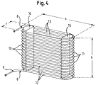
- the condenser 5 for example made of metal, in particular made of aluminum, copper or steel and in particular in the Fig. 3 closer to the condenser tube 6, which was, for example, three-dimensional wound spirally around a winding core, not shown, and having a first access 8 and a second access 9.
- refrigerant flows through the condenser tube 6.
- the three-dimensional spiral-shaped condenser tube 6 has, for example, in particular semicircular curved curved sections 10, 11 and the curved sections 10, 11 adjoining straight sections 12, 13.
- the condenser 5 comprises a fastening device comprising two partial fastening devices (webs) 14, 15 which are fastened to the condenser tube 6 within the space bounded by the condenser tube 6.
- the partial fastening devices 14, 15 are each formed in a semi-cylindrical shape and have a height which corresponds to the height h of the condenser 5.
- One of the partial fastening devices 14 is attached to the condenser tube 6 in the region of the curved section 10 of the condenser tube 6 and the other partial fastening device 15 is fastened to the condenser tube 6 in the region of the curved section 11 of the condenser tube 6.
- the radii of the semi-cylindrical sub-fixing devices 14, 15 thus correspond to the radii of the two semicircular curved sections 10, 11 of the condenser tube 6.
- the curved condenser tube 6 with attached thereto partial fastening devices 14, 15 is in the Fig. 4 shown.
- the sub-fastening devices 14, 15 are made for example of a noise-reducing or a sound-absorbing material such as rubber.
- the sectionbefest Trentsvoriquesen 14, 15 can also eg in their Inside a heat-storing medium, for example, in solid or liquid form, which promotes heat dissipation of the condenser 5.
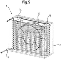
- the sub-fastening devices 14, 15 are provided that a fan 16 can be attached to them.
- the fan 16 includes e.g. a housing 17 on which a fan 18 is rotatably mounted.
- the fan 16 is in the case of the present embodiment with its housing 17 on the two sub-fastening devices 14, 15, e.g. fastened by means not shown snap hooks and is thus within the confined by the condenser tube 6 space.
- the fan 16 may e.g. be controlled by a control device of the household refrigerator 1 not shown in detail.
- the condenser 5 comprises one in the Fig. 5 shown shuttering 7, which is provided, for example, to direct the airflow generated by the fan 16 in operation.
- the condenser tube 6 can be wound over the winding core, not shown, which is subsequently removed. Thereafter, the sub-fastening devices 14, 15 are pushed with attached thereto fan 16 in the space bounded by the condenser tube 6 and then attached to the condenser tube 6.
Landscapes
- Engineering & Computer Science (AREA)
- Physics & Mathematics (AREA)
- Thermal Sciences (AREA)
- Mechanical Engineering (AREA)
- General Engineering & Computer Science (AREA)
- Heat-Exchange Devices With Radiators And Conduit Assemblies (AREA)
- Devices That Are Associated With Refrigeration Equipment (AREA)
Claims (9)
- Échangeur de chaleur, en particulier condenseur (5) pour un appareil frigorifique ménager (1), présentant un tube d'échangeur de chaleur (6) tridimensionnel, arqué au moins approximativement en spirale et un ventilateur (16) disposé dans l'espace délimité par le tube d'échangeur de chaleur (6), dans lequel un dispositif de fixation (14, 15) est prévu pour la fixation du ventilateur (16) au tube d'échangeur de chaleur (6), au moyen duquel dispositif le ventilateur (16) est fixé au tube d'échangeur de chaleur (6), dans lequel le tube d'échangeur de chaleur arqué (6) présente de premières sections courbées en particulier semi-circulaires disposées l'une au-dessus de l'autre et de deuxièmes sections courbées en particulier semi-circulaires disposées l'une au-dessus de l'autre, lesquelles sont reliées à des sections de l'échangeur de chaleur (6) exécutées en particulier de façon rectiligne, caractérisé en ce que le dispositif de fixation (14, 15) est exécuté de façon semi-cylindrique.
- Échangeur de chaleur, en particulier condenseur (5) pour un appareil frigorifique ménager (1), présentant un tube d'échangeur de chaleur (6) tridimensionnel, arqué au moins approximativement en spirale et un ventilateur (16) disposé dans l'espace délimité par le tube d'échangeur de chaleur (6), dans lequel un dispositif de fixation (14, 15) est prévu pour la fixation du ventilateur (16) au tube d'échangeur de chaleur (6), au moyen duquel dispositif le ventilateur (16) est fixé au tube d'échangeur de chaleur (6), caractérisé en ce que le dispositif de fixation (14, 15) est fabriqué en un matériau réduisant le bruit ou l'absorbant, et/ou présente en son sein une substance accumulatrice de chaleur fluide ou fixe.
- Échangeur de chaleur selon la revendication 1 ou 2, caractérisé en ce que le tube d'échangeur de chaleur (6) est fabriqué en métal, en particulier en aluminium, en cuivre ou en acier.
- Échangeur de chaleur selon la revendication 2 ou 3, caractérisé en ce que le tube d'échangeur de chaleur arqué (6) présente de premières sections (10) courbées en particulier semi-circulaires disposées l'une au-dessus de l'autre et de deuxièmes sections (11) courbées en particulier semi-circulaires disposées l'une au-dessus de l'autre, lesquelles sont reliées à des sections (12, 13) du tube d'échangeur de chaleur (6) exécutées en particulier de façon rectiligne.
- Échangeur de chaleur selon la revendication 1 à 4, caractérisé en ce que le dispositif de fixation présente un premier dispositif de fixation partielle (14) et un deuxième dispositif de fixation partielle (15), entre lesquels le ventilateur (16) est disposé.
- Échangeur de chaleur selon la revendication 4, caractérisé en ce que le dispositif de fixation (14, 15) est fixé à la première section et/ou à la deuxième section courbée (10, 11) du tube d'échangeur de chaleur (6).
- Échangeur de chaleur selon la revendication 4, caractérisé en ce que le dispositif de fixation (14, 15) est fixé par sa surface enveloppante en forme de segment circulaire à la première section ou à la deuxième section courbée (10, 11) du tube d'échangeur de chaleur (6).
- Échangeur de chaleur selon la revendication 1 à 7, caractérisé par un emboîtage (7) à l'intérieur duquel le tube d'échangeur de chaleur arqué (6) est disposé, en particulier fixé et qui présente en particulier une structure directrice pour l'écoulement d'air généré par le ventilateur (16).
- Appareil ménager présentant un espace frigorifique et un circuit frigorifique (4) réfrigérant l'espace frigorifique, avec un échangeur de chaleur, en particulier un condenseur (5), selon l'une des revendications 1 à 8.
Applications Claiming Priority (2)
| Application Number | Priority Date | Filing Date | Title |
|---|---|---|---|
| DE200910000844 DE102009000844A1 (de) | 2009-02-13 | 2009-02-13 | Wärmetauscher, insbesondere Verflüssiger für ein Haushaltskältegerät |
| PCT/EP2010/050970 WO2010091959A1 (fr) | 2009-02-13 | 2010-01-28 | Échangeur thermique, en particulier condenseur pour un appareil frigorifique domestique |
Publications (2)
| Publication Number | Publication Date |
|---|---|
| EP2396609A1 EP2396609A1 (fr) | 2011-12-21 |
| EP2396609B1 true EP2396609B1 (fr) | 2017-10-25 |
Family
ID=42312978
Family Applications (1)
| Application Number | Title | Priority Date | Filing Date |
|---|---|---|---|
| EP10701864.0A Not-in-force EP2396609B1 (fr) | 2009-02-13 | 2010-01-28 | Échangeur thermique, en particulier condenseur pour un appareil frigorifique domestique |
Country Status (3)
| Country | Link |
|---|---|
| EP (1) | EP2396609B1 (fr) |
| DE (1) | DE102009000844A1 (fr) |
| WO (1) | WO2010091959A1 (fr) |
Families Citing this family (1)
| Publication number | Priority date | Publication date | Assignee | Title |
|---|---|---|---|---|
| CN103017452B (zh) * | 2013-01-14 | 2015-04-22 | 合肥工业大学 | 组合有风扇的冰箱冷凝器 |
Family Cites Families (6)
| Publication number | Priority date | Publication date | Assignee | Title |
|---|---|---|---|---|
| US2610484A (en) | 1950-01-13 | 1952-09-16 | Betz Corp | Compact refrigeration unit for cooling air |
| US3759321A (en) * | 1971-10-22 | 1973-09-18 | Singer Co | Condenser coil apparatus |
| JPS5548300Y2 (fr) * | 1976-07-30 | 1980-11-12 | ||
| DE102005021554A1 (de) | 2005-05-10 | 2006-11-16 | BSH Bosch und Siemens Hausgeräte GmbH | Wärmetauscher für ein Kältegerät |
| KR100689148B1 (ko) * | 2005-07-15 | 2007-03-09 | 위니아만도 주식회사 | 스파이럴 타입 응축기에 적용되는 팬모터 장착용 홀더구조 |
| WO2008097208A2 (fr) * | 2007-02-08 | 2008-08-14 | Klimasan Klima Sanayi Ve Ticaret A.S. | Condensateur |
-
2009
- 2009-02-13 DE DE200910000844 patent/DE102009000844A1/de not_active Withdrawn
-
2010
- 2010-01-28 WO PCT/EP2010/050970 patent/WO2010091959A1/fr not_active Ceased
- 2010-01-28 EP EP10701864.0A patent/EP2396609B1/fr not_active Not-in-force
Non-Patent Citations (1)
| Title |
|---|
| None * |
Also Published As
| Publication number | Publication date |
|---|---|
| DE102009000844A1 (de) | 2010-08-19 |
| EP2396609A1 (fr) | 2011-12-21 |
| WO2010091959A1 (fr) | 2010-08-19 |
Similar Documents
| Publication | Publication Date | Title |
|---|---|---|
| EP2891396B1 (fr) | Dispositif de refroidissement pour des composants placés dans l'espace interne d'une armoire de commande | |
| DE102005052972A1 (de) | Doppelwandiges Rohr und dieses verwendende Kühlkreisvorrichtung | |
| EP2638337B1 (fr) | Évaporateur | |
| EP2396609B1 (fr) | Échangeur thermique, en particulier condenseur pour un appareil frigorifique domestique | |
| EP1722182B1 (fr) | Appareil de réfrigération et/ou de congélation | |
| DE102005021554A1 (de) | Wärmetauscher für ein Kältegerät | |
| EP2274560B1 (fr) | Appareil frigorifique | |
| DE10322028A1 (de) | Kälteanlage mit Wärmeaustauscher | |
| WO2009144067A1 (fr) | Réfrigérateur, en particulier réfrigérateur domestique, comprenant un condenseur à éléments accumulateurs thermiques | |
| DE202008017441U1 (de) | Kühl- und/oder Gefriergerät mit extrudierter Kühlmittelleitung | |
| DE202007010274U1 (de) | Wärmetauscher und Kältegerät | |
| WO2015018646A1 (fr) | Réfrigérateur équipé d'un évaporateur | |
| DE102014211112A1 (de) | Verflüssigerbaugruppe für ein Kältegerät | |
| DE10297119B4 (de) | Kondensator, Verdampfer und Kühlvorrichtung | |
| DE822396C (de) | Drosselventil fuer Kaeltemaschinen | |
| DE102011079762A1 (de) | Wärmetauscher für ein kältegerät, verfahren zur herstellung eines wärmetauschers sowie kältegerät | |
| EP3569953A1 (fr) | Dispositif de circuit réfrigérant et procédé de fonctionnement d'un dispositif de circuit réfrigérant doté d'un évaporateur hybride | |
| EP2054678B1 (fr) | Appareil de refroidissement et/ou de congélation | |
| DE19506904A1 (de) | Kältemittelverdampfer für ein Kühlmöbel | |
| EP1746366A1 (fr) | Condenseur du type tuyau-plaque pour des installations frigorifiques | |
| DE1003236B (de) | Waermeaustauscher, insbesondere Verdampfer fuer Kuehlschraenke u. dgl. | |
| DE102019110019A1 (de) | Elektrisches Heizelement für Absorptionskühlschränke | |
| DE102015207842A1 (de) | Kältegerät mit einem Heizabschnitt | |
| WO2012028447A2 (fr) | Appareil de froid | |
| DD267552A1 (de) | Verfluessiger fuer geraete der kleinkaeltetechnik |
Legal Events
| Date | Code | Title | Description |
|---|---|---|---|
| PUAI | Public reference made under article 153(3) epc to a published international application that has entered the european phase |
Free format text: ORIGINAL CODE: 0009012 |
|
| 17P | Request for examination filed |
Effective date: 20110913 |
|
| AK | Designated contracting states |
Kind code of ref document: A1 Designated state(s): AT BE BG CH CY CZ DE DK EE ES FI FR GB GR HR HU IE IS IT LI LT LU LV MC MK MT NL NO PL PT RO SE SI SK SM TR |
|
| DAX | Request for extension of the european patent (deleted) | ||
| RAP1 | Party data changed (applicant data changed or rights of an application transferred) |
Owner name: BSH HAUSGERAETE GMBH |
|
| GRAP | Despatch of communication of intention to grant a patent |
Free format text: ORIGINAL CODE: EPIDOSNIGR1 |
|
| GRAJ | Information related to disapproval of communication of intention to grant by the applicant or resumption of examination proceedings by the epo deleted |
Free format text: ORIGINAL CODE: EPIDOSDIGR1 |
|
| GRAP | Despatch of communication of intention to grant a patent |
Free format text: ORIGINAL CODE: EPIDOSNIGR1 |
|
| INTG | Intention to grant announced |
Effective date: 20170531 |
|
| GRAS | Grant fee paid |
Free format text: ORIGINAL CODE: EPIDOSNIGR3 |
|
| GRAA | (expected) grant |
Free format text: ORIGINAL CODE: 0009210 |
|
| AK | Designated contracting states |
Kind code of ref document: B1 Designated state(s): AT BE BG CH CY CZ DE DK EE ES FI FR GB GR HR HU IE IS IT LI LT LU LV MC MK MT NL NO PL PT RO SE SI SK SM TR |
|
| REG | Reference to a national code |
Ref country code: GB Ref legal event code: FG4D Free format text: NOT ENGLISH |
|
| REG | Reference to a national code |
Ref country code: CH Ref legal event code: EP |
|
| REG | Reference to a national code |
Ref country code: AT Ref legal event code: REF Ref document number: 940309 Country of ref document: AT Kind code of ref document: T Effective date: 20171115 |
|
| REG | Reference to a national code |
Ref country code: IE Ref legal event code: FG4D Free format text: LANGUAGE OF EP DOCUMENT: GERMAN |
|
| REG | Reference to a national code |
Ref country code: DE Ref legal event code: R096 Ref document number: 502010014300 Country of ref document: DE |
|
| REG | Reference to a national code |
Ref country code: NL Ref legal event code: MP Effective date: 20171025 |
|
| REG | Reference to a national code |
Ref country code: LT Ref legal event code: MG4D |
|
| PG25 | Lapsed in a contracting state [announced via postgrant information from national office to epo] |
Ref country code: NL Free format text: LAPSE BECAUSE OF FAILURE TO SUBMIT A TRANSLATION OF THE DESCRIPTION OR TO PAY THE FEE WITHIN THE PRESCRIBED TIME-LIMIT Effective date: 20171025 |
|
| PG25 | Lapsed in a contracting state [announced via postgrant information from national office to epo] |
Ref country code: LT Free format text: LAPSE BECAUSE OF FAILURE TO SUBMIT A TRANSLATION OF THE DESCRIPTION OR TO PAY THE FEE WITHIN THE PRESCRIBED TIME-LIMIT Effective date: 20171025 Ref country code: FI Free format text: LAPSE BECAUSE OF FAILURE TO SUBMIT A TRANSLATION OF THE DESCRIPTION OR TO PAY THE FEE WITHIN THE PRESCRIBED TIME-LIMIT Effective date: 20171025 Ref country code: SE Free format text: LAPSE BECAUSE OF FAILURE TO SUBMIT A TRANSLATION OF THE DESCRIPTION OR TO PAY THE FEE WITHIN THE PRESCRIBED TIME-LIMIT Effective date: 20171025 Ref country code: NO Free format text: LAPSE BECAUSE OF FAILURE TO SUBMIT A TRANSLATION OF THE DESCRIPTION OR TO PAY THE FEE WITHIN THE PRESCRIBED TIME-LIMIT Effective date: 20180125 Ref country code: ES Free format text: LAPSE BECAUSE OF FAILURE TO SUBMIT A TRANSLATION OF THE DESCRIPTION OR TO PAY THE FEE WITHIN THE PRESCRIBED TIME-LIMIT Effective date: 20171025 |
|
| PG25 | Lapsed in a contracting state [announced via postgrant information from national office to epo] |
Ref country code: IS Free format text: LAPSE BECAUSE OF FAILURE TO SUBMIT A TRANSLATION OF THE DESCRIPTION OR TO PAY THE FEE WITHIN THE PRESCRIBED TIME-LIMIT Effective date: 20180225 Ref country code: BG Free format text: LAPSE BECAUSE OF FAILURE TO SUBMIT A TRANSLATION OF THE DESCRIPTION OR TO PAY THE FEE WITHIN THE PRESCRIBED TIME-LIMIT Effective date: 20180125 Ref country code: LV Free format text: LAPSE BECAUSE OF FAILURE TO SUBMIT A TRANSLATION OF THE DESCRIPTION OR TO PAY THE FEE WITHIN THE PRESCRIBED TIME-LIMIT Effective date: 20171025 Ref country code: GR Free format text: LAPSE BECAUSE OF FAILURE TO SUBMIT A TRANSLATION OF THE DESCRIPTION OR TO PAY THE FEE WITHIN THE PRESCRIBED TIME-LIMIT Effective date: 20180126 Ref country code: HR Free format text: LAPSE BECAUSE OF FAILURE TO SUBMIT A TRANSLATION OF THE DESCRIPTION OR TO PAY THE FEE WITHIN THE PRESCRIBED TIME-LIMIT Effective date: 20171025 |
|
| PGFP | Annual fee paid to national office [announced via postgrant information from national office to epo] |
Ref country code: TR Payment date: 20180125 Year of fee payment: 9 |
|
| REG | Reference to a national code |
Ref country code: DE Ref legal event code: R097 Ref document number: 502010014300 Country of ref document: DE |
|
| PG25 | Lapsed in a contracting state [announced via postgrant information from national office to epo] |
Ref country code: DK Free format text: LAPSE BECAUSE OF FAILURE TO SUBMIT A TRANSLATION OF THE DESCRIPTION OR TO PAY THE FEE WITHIN THE PRESCRIBED TIME-LIMIT Effective date: 20171025 Ref country code: EE Free format text: LAPSE BECAUSE OF FAILURE TO SUBMIT A TRANSLATION OF THE DESCRIPTION OR TO PAY THE FEE WITHIN THE PRESCRIBED TIME-LIMIT Effective date: 20171025 Ref country code: CY Free format text: LAPSE BECAUSE OF FAILURE TO SUBMIT A TRANSLATION OF THE DESCRIPTION OR TO PAY THE FEE WITHIN THE PRESCRIBED TIME-LIMIT Effective date: 20171025 Ref country code: CZ Free format text: LAPSE BECAUSE OF FAILURE TO SUBMIT A TRANSLATION OF THE DESCRIPTION OR TO PAY THE FEE WITHIN THE PRESCRIBED TIME-LIMIT Effective date: 20171025 Ref country code: SK Free format text: LAPSE BECAUSE OF FAILURE TO SUBMIT A TRANSLATION OF THE DESCRIPTION OR TO PAY THE FEE WITHIN THE PRESCRIBED TIME-LIMIT Effective date: 20171025 |
|
| REG | Reference to a national code |
Ref country code: DE Ref legal event code: R119 Ref document number: 502010014300 Country of ref document: DE |
|
| PG25 | Lapsed in a contracting state [announced via postgrant information from national office to epo] |
Ref country code: PL Free format text: LAPSE BECAUSE OF FAILURE TO SUBMIT A TRANSLATION OF THE DESCRIPTION OR TO PAY THE FEE WITHIN THE PRESCRIBED TIME-LIMIT Effective date: 20171025 Ref country code: RO Free format text: LAPSE BECAUSE OF FAILURE TO SUBMIT A TRANSLATION OF THE DESCRIPTION OR TO PAY THE FEE WITHIN THE PRESCRIBED TIME-LIMIT Effective date: 20171025 Ref country code: IT Free format text: LAPSE BECAUSE OF FAILURE TO SUBMIT A TRANSLATION OF THE DESCRIPTION OR TO PAY THE FEE WITHIN THE PRESCRIBED TIME-LIMIT Effective date: 20171025 Ref country code: SM Free format text: LAPSE BECAUSE OF FAILURE TO SUBMIT A TRANSLATION OF THE DESCRIPTION OR TO PAY THE FEE WITHIN THE PRESCRIBED TIME-LIMIT Effective date: 20171025 |
|
| PLBE | No opposition filed within time limit |
Free format text: ORIGINAL CODE: 0009261 |
|
| REG | Reference to a national code |
Ref country code: CH Ref legal event code: PL |
|
| STAA | Information on the status of an ep patent application or granted ep patent |
Free format text: STATUS: NO OPPOSITION FILED WITHIN TIME LIMIT |
|
| GBPC | Gb: european patent ceased through non-payment of renewal fee |
Effective date: 20180128 |
|
| PG25 | Lapsed in a contracting state [announced via postgrant information from national office to epo] |
Ref country code: MT Free format text: LAPSE BECAUSE OF FAILURE TO SUBMIT A TRANSLATION OF THE DESCRIPTION OR TO PAY THE FEE WITHIN THE PRESCRIBED TIME-LIMIT Effective date: 20171025 |
|
| 26N | No opposition filed |
Effective date: 20180726 |
|
| PG25 | Lapsed in a contracting state [announced via postgrant information from national office to epo] |
Ref country code: LU Free format text: LAPSE BECAUSE OF NON-PAYMENT OF DUE FEES Effective date: 20180128 Ref country code: DE Free format text: LAPSE BECAUSE OF NON-PAYMENT OF DUE FEES Effective date: 20180801 Ref country code: FR Free format text: LAPSE BECAUSE OF NON-PAYMENT OF DUE FEES Effective date: 20180131 |
|
| REG | Reference to a national code |
Ref country code: IE Ref legal event code: MM4A |
|
| REG | Reference to a national code |
Ref country code: FR Ref legal event code: ST Effective date: 20180928 |
|
| REG | Reference to a national code |
Ref country code: BE Ref legal event code: MM Effective date: 20180131 |
|
| PG25 | Lapsed in a contracting state [announced via postgrant information from national office to epo] |
Ref country code: LI Free format text: LAPSE BECAUSE OF NON-PAYMENT OF DUE FEES Effective date: 20180131 Ref country code: CH Free format text: LAPSE BECAUSE OF NON-PAYMENT OF DUE FEES Effective date: 20180131 Ref country code: SI Free format text: LAPSE BECAUSE OF FAILURE TO SUBMIT A TRANSLATION OF THE DESCRIPTION OR TO PAY THE FEE WITHIN THE PRESCRIBED TIME-LIMIT Effective date: 20171025 Ref country code: BE Free format text: LAPSE BECAUSE OF NON-PAYMENT OF DUE FEES Effective date: 20180131 Ref country code: GB Free format text: LAPSE BECAUSE OF NON-PAYMENT OF DUE FEES Effective date: 20180128 |
|
| PG25 | Lapsed in a contracting state [announced via postgrant information from national office to epo] |
Ref country code: IE Free format text: LAPSE BECAUSE OF NON-PAYMENT OF DUE FEES Effective date: 20180128 |
|
| REG | Reference to a national code |
Ref country code: AT Ref legal event code: MM01 Ref document number: 940309 Country of ref document: AT Kind code of ref document: T Effective date: 20180128 |
|
| PG25 | Lapsed in a contracting state [announced via postgrant information from national office to epo] |
Ref country code: AT Free format text: LAPSE BECAUSE OF NON-PAYMENT OF DUE FEES Effective date: 20180128 |
|
| PG25 | Lapsed in a contracting state [announced via postgrant information from national office to epo] |
Ref country code: MC Free format text: LAPSE BECAUSE OF FAILURE TO SUBMIT A TRANSLATION OF THE DESCRIPTION OR TO PAY THE FEE WITHIN THE PRESCRIBED TIME-LIMIT Effective date: 20171025 |
|
| PG25 | Lapsed in a contracting state [announced via postgrant information from national office to epo] |
Ref country code: PT Free format text: LAPSE BECAUSE OF FAILURE TO SUBMIT A TRANSLATION OF THE DESCRIPTION OR TO PAY THE FEE WITHIN THE PRESCRIBED TIME-LIMIT Effective date: 20171025 Ref country code: HU Free format text: LAPSE BECAUSE OF FAILURE TO SUBMIT A TRANSLATION OF THE DESCRIPTION OR TO PAY THE FEE WITHIN THE PRESCRIBED TIME-LIMIT; INVALID AB INITIO Effective date: 20100128 |
|
| PG25 | Lapsed in a contracting state [announced via postgrant information from national office to epo] |
Ref country code: MK Free format text: LAPSE BECAUSE OF NON-PAYMENT OF DUE FEES Effective date: 20171025 |
|
| PG25 | Lapsed in a contracting state [announced via postgrant information from national office to epo] |
Ref country code: TR Free format text: LAPSE BECAUSE OF NON-PAYMENT OF DUE FEES Effective date: 20190128 |