EP2396859B1 - Optische kommunikation mithilfe gemeinsam genutzter optischer pumpen - Google Patents
Optische kommunikation mithilfe gemeinsam genutzter optischer pumpen Download PDFInfo
- Publication number
- EP2396859B1 EP2396859B1 EP10741833.7A EP10741833A EP2396859B1 EP 2396859 B1 EP2396859 B1 EP 2396859B1 EP 10741833 A EP10741833 A EP 10741833A EP 2396859 B1 EP2396859 B1 EP 2396859B1
- Authority
- EP
- European Patent Office
- Prior art keywords
- optical
- pump
- power
- fiber
- amplification
- Prior art date
- Legal status (The legal status is an assumption and is not a legal conclusion. Google has not performed a legal analysis and makes no representation as to the accuracy of the status listed.)
- Active
Links
- 230000003287 optical effect Effects 0.000 title claims description 610
- 239000013307 optical fiber Substances 0.000 claims description 126
- 238000001069 Raman spectroscopy Methods 0.000 claims description 106
- 230000003321 amplification Effects 0.000 claims description 92
- 238000003199 nucleic acid amplification method Methods 0.000 claims description 92
- 239000000835 fiber Substances 0.000 claims description 76
- 239000013589 supplement Substances 0.000 claims description 6
- 229910052761 rare earth metal Inorganic materials 0.000 claims description 5
- 150000002910 rare earth metals Chemical class 0.000 claims description 5
- FFKXTXJQZGIKQZ-UHFFFAOYSA-N ROPA Natural products O1C2C3C=C(CO)CC(C(C(C)=C4)=O)(O)C4C3(O3)C(C)CC2(C(C)=C)OC31CC1=CC=CC=C1 FFKXTXJQZGIKQZ-UHFFFAOYSA-N 0.000 description 12
- 230000005540 biological transmission Effects 0.000 description 8
- 230000007246 mechanism Effects 0.000 description 8
- 239000006185 dispersion Substances 0.000 description 4
- 230000006872 improvement Effects 0.000 description 4
- 229910052691 Erbium Inorganic materials 0.000 description 3
- 230000008878 coupling Effects 0.000 description 3
- 238000010168 coupling process Methods 0.000 description 3
- 238000005859 coupling reaction Methods 0.000 description 3
- UYAHIZSMUZPPFV-UHFFFAOYSA-N erbium Chemical compound [Er] UYAHIZSMUZPPFV-UHFFFAOYSA-N 0.000 description 3
- 239000004065 semiconductor Substances 0.000 description 3
- 239000008186 active pharmaceutical agent Substances 0.000 description 2
- 230000008901 benefit Effects 0.000 description 2
- 239000004020 conductor Substances 0.000 description 2
- 230000003247 decreasing effect Effects 0.000 description 2
- 238000001914 filtration Methods 0.000 description 2
- 238000005086 pumping Methods 0.000 description 2
- 230000002776 aggregation Effects 0.000 description 1
- 238000004220 aggregation Methods 0.000 description 1
- 230000002457 bidirectional effect Effects 0.000 description 1
- 230000001419 dependent effect Effects 0.000 description 1
- 238000010586 diagram Methods 0.000 description 1
- 230000000694 effects Effects 0.000 description 1
- 230000005611 electricity Effects 0.000 description 1
- 238000002955 isolation Methods 0.000 description 1
- 230000028161 membrane depolarization Effects 0.000 description 1
- 230000002093 peripheral effect Effects 0.000 description 1
- 230000010287 polarization Effects 0.000 description 1
- 230000000644 propagated effect Effects 0.000 description 1
Images




Classifications
-
- H—ELECTRICITY
- H04—ELECTRIC COMMUNICATION TECHNIQUE
- H04B—TRANSMISSION
- H04B10/00—Transmission systems employing electromagnetic waves other than radio-waves, e.g. infrared, visible or ultraviolet light, or employing corpuscular radiation, e.g. quantum communication
- H04B10/29—Repeaters
- H04B10/291—Repeaters in which processing or amplification is carried out without conversion of the main signal from optical form
- H04B10/2912—Repeaters in which processing or amplification is carried out without conversion of the main signal from optical form characterised by the medium used for amplification or processing
- H04B10/2916—Repeaters in which processing or amplification is carried out without conversion of the main signal from optical form characterised by the medium used for amplification or processing using Raman or Brillouin amplifiers
-
- H—ELECTRICITY
- H01—ELECTRIC ELEMENTS
- H01S—DEVICES USING THE PROCESS OF LIGHT AMPLIFICATION BY STIMULATED EMISSION OF RADIATION [LASER] TO AMPLIFY OR GENERATE LIGHT; DEVICES USING STIMULATED EMISSION OF ELECTROMAGNETIC RADIATION IN WAVE RANGES OTHER THAN OPTICAL
- H01S3/00—Lasers, i.e. devices using stimulated emission of electromagnetic radiation in the infrared, visible or ultraviolet wave range
- H01S3/05—Construction or shape of optical resonators; Accommodation of active medium therein; Shape of active medium
- H01S3/06—Construction or shape of active medium
- H01S3/063—Waveguide lasers, i.e. whereby the dimensions of the waveguide are of the order of the light wavelength
- H01S3/067—Fibre lasers
- H01S3/06754—Fibre amplifiers
- H01S3/06758—Tandem amplifiers
-
- H—ELECTRICITY
- H01—ELECTRIC ELEMENTS
- H01S—DEVICES USING THE PROCESS OF LIGHT AMPLIFICATION BY STIMULATED EMISSION OF RADIATION [LASER] TO AMPLIFY OR GENERATE LIGHT; DEVICES USING STIMULATED EMISSION OF ELECTROMAGNETIC RADIATION IN WAVE RANGES OTHER THAN OPTICAL
- H01S3/00—Lasers, i.e. devices using stimulated emission of electromagnetic radiation in the infrared, visible or ultraviolet wave range
- H01S3/09—Processes or apparatus for excitation, e.g. pumping
- H01S3/091—Processes or apparatus for excitation, e.g. pumping using optical pumping
- H01S3/094—Processes or apparatus for excitation, e.g. pumping using optical pumping by coherent light
- H01S3/094061—Shared pump, i.e. pump light of a single pump source is used to pump plural gain media in parallel
-
- H—ELECTRICITY
- H01—ELECTRIC ELEMENTS
- H01S—DEVICES USING THE PROCESS OF LIGHT AMPLIFICATION BY STIMULATED EMISSION OF RADIATION [LASER] TO AMPLIFY OR GENERATE LIGHT; DEVICES USING STIMULATED EMISSION OF ELECTROMAGNETIC RADIATION IN WAVE RANGES OTHER THAN OPTICAL
- H01S3/00—Lasers, i.e. devices using stimulated emission of electromagnetic radiation in the infrared, visible or ultraviolet wave range
- H01S3/30—Lasers, i.e. devices using stimulated emission of electromagnetic radiation in the infrared, visible or ultraviolet wave range using scattering effects, e.g. stimulated Brillouin or Raman effects
- H01S3/302—Lasers, i.e. devices using stimulated emission of electromagnetic radiation in the infrared, visible or ultraviolet wave range using scattering effects, e.g. stimulated Brillouin or Raman effects in an optical fibre
-
- H—ELECTRICITY
- H04—ELECTRIC COMMUNICATION TECHNIQUE
- H04B—TRANSMISSION
- H04B10/00—Transmission systems employing electromagnetic waves other than radio-waves, e.g. infrared, visible or ultraviolet light, or employing corpuscular radiation, e.g. quantum communication
- H04B10/29—Repeaters
- H04B10/291—Repeaters in which processing or amplification is carried out without conversion of the main signal from optical form
- H04B10/293—Signal power control
- H04B10/2933—Signal power control considering the whole optical path
- H04B10/2935—Signal power control considering the whole optical path with a cascade of amplifiers
-
- H—ELECTRICITY
- H01—ELECTRIC ELEMENTS
- H01S—DEVICES USING THE PROCESS OF LIGHT AMPLIFICATION BY STIMULATED EMISSION OF RADIATION [LASER] TO AMPLIFY OR GENERATE LIGHT; DEVICES USING STIMULATED EMISSION OF ELECTROMAGNETIC RADIATION IN WAVE RANGES OTHER THAN OPTICAL
- H01S2301/00—Functional characteristics
- H01S2301/04—Gain spectral shaping, flattening
-
- H—ELECTRICITY
- H01—ELECTRIC ELEMENTS
- H01S—DEVICES USING THE PROCESS OF LIGHT AMPLIFICATION BY STIMULATED EMISSION OF RADIATION [LASER] TO AMPLIFY OR GENERATE LIGHT; DEVICES USING STIMULATED EMISSION OF ELECTROMAGNETIC RADIATION IN WAVE RANGES OTHER THAN OPTICAL
- H01S3/00—Lasers, i.e. devices using stimulated emission of electromagnetic radiation in the infrared, visible or ultraviolet wave range
- H01S3/09—Processes or apparatus for excitation, e.g. pumping
- H01S3/091—Processes or apparatus for excitation, e.g. pumping using optical pumping
- H01S3/094—Processes or apparatus for excitation, e.g. pumping using optical pumping by coherent light
- H01S3/094003—Processes or apparatus for excitation, e.g. pumping using optical pumping by coherent light the pumped medium being a fibre
-
- H—ELECTRICITY
- H01—ELECTRIC ELEMENTS
- H01S—DEVICES USING THE PROCESS OF LIGHT AMPLIFICATION BY STIMULATED EMISSION OF RADIATION [LASER] TO AMPLIFY OR GENERATE LIGHT; DEVICES USING STIMULATED EMISSION OF ELECTROMAGNETIC RADIATION IN WAVE RANGES OTHER THAN OPTICAL
- H01S3/00—Lasers, i.e. devices using stimulated emission of electromagnetic radiation in the infrared, visible or ultraviolet wave range
- H01S3/09—Processes or apparatus for excitation, e.g. pumping
- H01S3/091—Processes or apparatus for excitation, e.g. pumping using optical pumping
- H01S3/094—Processes or apparatus for excitation, e.g. pumping using optical pumping by coherent light
- H01S3/0941—Processes or apparatus for excitation, e.g. pumping using optical pumping by coherent light of a laser diode
- H01S3/09415—Processes or apparatus for excitation, e.g. pumping using optical pumping by coherent light of a laser diode the pumping beam being parallel to the lasing mode of the pumped medium, e.g. end-pumping
-
- H—ELECTRICITY
- H01—ELECTRIC ELEMENTS
- H01S—DEVICES USING THE PROCESS OF LIGHT AMPLIFICATION BY STIMULATED EMISSION OF RADIATION [LASER] TO AMPLIFY OR GENERATE LIGHT; DEVICES USING STIMULATED EMISSION OF ELECTROMAGNETIC RADIATION IN WAVE RANGES OTHER THAN OPTICAL
- H01S3/00—Lasers, i.e. devices using stimulated emission of electromagnetic radiation in the infrared, visible or ultraviolet wave range
- H01S3/14—Lasers, i.e. devices using stimulated emission of electromagnetic radiation in the infrared, visible or ultraviolet wave range characterised by the material used as the active medium
- H01S3/16—Solid materials
- H01S3/1601—Solid materials characterised by an active (lasing) ion
- H01S3/1603—Solid materials characterised by an active (lasing) ion rare earth
- H01S3/1608—Solid materials characterised by an active (lasing) ion rare earth erbium
-
- H—ELECTRICITY
- H01—ELECTRIC ELEMENTS
- H01S—DEVICES USING THE PROCESS OF LIGHT AMPLIFICATION BY STIMULATED EMISSION OF RADIATION [LASER] TO AMPLIFY OR GENERATE LIGHT; DEVICES USING STIMULATED EMISSION OF ELECTROMAGNETIC RADIATION IN WAVE RANGES OTHER THAN OPTICAL
- H01S3/00—Lasers, i.e. devices using stimulated emission of electromagnetic radiation in the infrared, visible or ultraviolet wave range
- H01S3/23—Arrangements of two or more lasers not provided for in groups H01S3/02 - H01S3/22, e.g. tandem arrangements of separate active media
- H01S3/2375—Hybrid lasers
Definitions
- Fiber-optic communication networks serve a key demand of the information age by providing high-speed data between network nodes.
- Fiber optic communication networks include an aggregation of interconnected fiber-optic links.
- a fiber-optic link involves an optical signal source that emits information in the form of light into an optical fiber. Due to principles of internal reflection, the optical signal propagates through the optical fiber until it is eventually received into an optical signal receiver. If the fiber-optic link is bi-directional, information may be optically communicated in reverse typically using a separate optical fiber.
- Fiber-optic links are used in a wide variety of applications, each requiring different lengths of fiber-optic links. For instance, relatively short fiber-optic links may be used to communicate information between a computer and its proximate peripherals, or between local video source (such as a DVD or DVR) and a television. On the opposite extreme, however, fiber-optic links may extend hundreds or even thousands of kilometers when the information is to be communicated between two network nodes.
- Long-haul and ultra-long-haul optics refers to the transmission of light signals over long fiber-optic links on the order of hundreds or thousands of kilometers. Transmission of optic signals over such long distances presents enormous technical challenges. Significant time and resources may be required for any improvement in the art of long-haul and ultra-long-haul optical communication. Each improvement can represent a significant advance since such improvements often lead to the more widespread availability of communication throughout the globe. Thus, such advances may potentially accelerate humankind's ability to collaborate, learn, do business, and the like, regardless of where an individual resides on the globe.
- US 6 204 960 B1 discloses an optical apparatus for use in a soliton signal fiber optic transmission system, comprising a discrete erbium doped fiber optical amplifier repeater and adjacent fiber segment comprising distributed Raman amplification means, wherein common pumping means are used for the discrete amplifier and the distributed amplification means.
- an optical pump unit may output optical pump power that is shared amongst a discrete optical amplification unit and a distributed optical amplification unit (such as a forward and/or backward Raman amplifier).
- a distributed optical amplification unit such as a forward and/or backward Raman amplifier.
- the output pump power from optical pump units is cross-distributed amongst multiple amplifier gain stages even in a single direction of an optical link in an optical communications system.
- an optical pump unit may output optical pump power that is shared amongst a discrete optical amplification unit and a distributed optical amplification unit (such as a forward and/or backward Raman distributed amplification). Such sharing has the potential to increase reliability and/or efficiency of the optical communications system.
- FIG 1 schematically illustrates an example optical communications system 100 in which the principles described herein may be employed.
- information is communicated between terminals 101 and 102 via the use of optical signals.
- optical signals travelling from the terminal 101 to terminal 102 will be referred to as being “eastern”
- optical signals traveling from the terminal 102 to the terminal 101 will be referred to as being “western”.
- the terms “eastern” and “western” are simply terms of art used to allow for easy distinction between the two optical signals traveling in opposite directions.
- the use of the terms “eastern” and “western” does not imply any actual geographical relation of components in Figure 1 , nor to any actual physical direction of optical signals.
- terminal 101 may be geographical located eastward of the terminal 102, even though the convention used herein has “eastern” optical signals traveling from the terminal 101 to the terminal 102.
- the optical signals are Wavelength Division Multiplexed (WDM) and potentially Dense Wavelength Division Multiplexed (DWDM).
- WDM or DWDM information is communicated over each of multiple distinct optical channels called hereinafter "wavelength division optical channels".
- Each wavelength division optical channel is allocated a particular frequency for optical communication.
- the terminal 101 may have "n" optical transmitters 111 (including optical transmitters 111(1) through 111(n), where n is a positive integer), each optical transmitter for transmitting over a corresponding eastern wavelength division optical channel.
- the terminal 102 may have "n" optical transmitters 121 including optical transmitters 121(1) through 121(n), each also for transmitting over a corresponding western wavelength division optical channel.
- the principles described herein are not limited, however, to communications in which the number of eastern wavelength division optical channels is the same as the number of western wavelength division optical channels.
- the principles described herein are not limited to the precise structure of the each of the optical transmitters.
- lasers are an appropriate optical transmitter for transmitting at a particular frequency. That said, the optical transmitters may each even be multiple laser transmitters, and may be tunable within a frequency range.
- the terminal 101 multiplexes each of the eastern optical signals from the optical transmitters 111 into a single eastern optical signal using optical multiplexer 112, which may then be optically amplified by an optional eastern optical amplifier 113 prior to being transmitted onto a first fiber link 114(1).
- the eastern optical signal from the final optical fiber link 114(m+1) is then optionally amplified at the terminal 102 by the optional optical amplifier 116.
- the eastern optical signal is then demultiplexed into the various wavelength division optical channels using optical demultiplexer 117.
- the various wavelength division optical channels may then be received and processed by corresponding optical receivers 118 including receivers 118(1) through 118(n).
- the terminal 102 multiplexes each of the western optical signals from the optical transmitters 121 (including optical transmitters 121(1) through 121(n)) into a single western optical signal using the optical multiplexer 122.
- the multiplexed optical signal may then be optically amplified by an optional western optical amplifier 123 prior to being transmitted onto a first fiber link 124(m+1).
- the western optical channel is symmetric with the eastern optical channel, there are once again "m” repeaters 125 (labeled 125(1) through 125(m)), and "m+1" optical fiber links 124 (labeled 124(1) through 124(m+1)). Recall that in an unrepeatered environment, "m” may be zero such that there is only one optical fiber link 124(1) and no repeaters 125 in the western channel.
- the western optical signal from the final optical fiber link 124(1) is then optionally amplified at the terminal 101 by the optional optical amplifier 126.
- the western optical signal is then demultiplexed using optical demultiplexer 127, whereupon the individual wavelength division optical channels are received and processed by the receivers 128 (including receivers 128(1) through 128(n)).
- Terminals 101 and/or 102 do not require all the elements shown in optical communication system 100.
- optical amplifiers 113, 116, 123, and/or 126 might not be used in some configurations.
- each of the corresponding optical amplifiers 113, 116, 123 and/or 126 may be a combination of multiple optical amplifiers if desired.
- the optical path length between repeaters is approximately the same.
- the distance between repeaters will depend on the total terminal-to-terminal optical path distance, the data rate, the quality of the optical fiber, the loss-characteristics of the fiber, the number of repeaters (if any), the amount of electrical power deliverable to each repeater (if there are repeaters), and so forth.
- a typical optical path length between repeaters (or from terminal to terminal in an unrepeatered system) for high-quality single mode fiber might be about 50 kilometers, and in practice may range from 30 kilometers or less to 90 kilometers or more. That said, the principles described herein are not limited to any particular optical path distances between repeaters, nor are they limited to repeater systems in which the optical path distances are the same from one repeatered segment to the next.
- the optical communications system 100 is represented in simplified form for purpose of illustration and example only.
- the principles described herein may extend to much more complex optical communications systems.
- the principles described herein may apply to optical communications in which there are multiple fiber pairs, each for communicating multiplexed WDM optical signals.
- the principles described herein also apply to optical communications in which there are one or more branching nodes that split one or more fiber pairs and/or wavelength division optical channels in one direction, and one or more fiber pairs and/or wavelength division optical channels in another direction.
- FIG 2 illustrates an optical apparatus 200 useful for understanding the invention that may be used in an optical communications system such as the optical communications system 100 of Figure 1 .
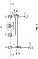
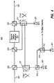
- Figures 3 through 5 illustrated optical apparatuses 300, 400 and 500 in accordance with the invention, which in that order added successive components. Figures 2 through 5 will now be described in that order.
- the optical apparatus 200 may be integrated with one of the eastern repeaters 115 or one of the western repeaters 125.
- the optical apparatus 200 (or any of the apparatuses 300, 400 or 500) may also be integrated with one of the terminals 101 and 102, regardless of whether the optical communications system 100 is a repeatered optical system or an unrepeatered optical system.
- the optical signal may be in an eastern optical signal, or a western optical signal, and may be traveling from left to right or from right to left in Figure 2.
- Figures 2 , 3 , 4 , and 5 may include additional components not shown in the figures that may, for example, provide optical isolation or, for example, provide optical depolarization.
- the discrete amplifier 231 might be the discrete amplifier 113 of Figure 1 and the optical fiber span 241 may be the optical fiber span 114(1) of Figure 1 .
- the optical signal would be an eastern optical signal traveling from left to right in Figure 2 , and the portion k 1 of the optical pump power would be used to perform forward Raman amplification of the eastern optical signal.
- the discrete amplifier 231 might be the discrete amplifier 126 of Figure 1 and the optical fiber span 241 may be the optical fiber span 124(1) of Figure 1 .
- the optical signal would be a western optical signal traveling from right to left in Figure 2 , and the portion k 1 of the optical pump power would be used to perform backward Raman amplification of the western optical signal.
- the discrete amplifier 231 might be the discrete amplifier 116 of Figure 1 and the optical fiber span 241 may be the optical fiber span 114(m+1) of Figure 1 .
- the optical signal would be an eastern optical signal traveling from right to left in Figure 2 (which means that the optical apparatus 200 would be horizontally flipped in order to fit into the terminal 102 as shown in Figure 1 ).
- the portion k 1 of the optical pump power would be used to perform backward Raman amplification of the eastern optical signal.
- the discrete amplifier 231 might be the discrete amplifier 123 of Figure 1 and the optical fiber span 241 may be the optical fiber span 124(m+1) of Figure 1 .
- the optical signal would be a western optical signal traveling from left to right in Figure 2 (which once again means that the optical apparatus 200 would be horizontally flipped in order to fit into the terminal 102 as shown in Figure 1 ).
- the portion k 1 of the optical pump power would be used to perform forward Raman amplification of the western optical signal.
- the optical apparatus 200 may be incorporated into any one of the eastern repeaters 115(k), where k is equal to any integer from 1 to m.
- the eastern optical signal could be traveling from left to right in Figure 2 , in which case optical fiber span 241 would be optical fiber span 114(k+1) of Figure 1 , and the portion k 1 of the optical pump power would be used to perform forward Raman amplification of the eastern optical signal.
- the optical signal is an eastern optical signal traveling from right to left in Figure 2 (which means that the optical apparatus 200 would be horizontally flipped to fit into Figure 1 )
- the optical fiber span 241 would be the optical fiber span 114(k) of Figure 1
- the portion k 1 of the optical pump power would be used to perform backward Raman amplification of the eastern optical signal.
- the optical apparatus 200 may be incorporated into any one of the western repeaters 125(k), where k is equal to any integer from 1 to m.
- the western optical signal could be traveling from left to right in Figure 2 (which means that the optical apparatus 200 would be horizontally flipped to fit into Figure 1 ), in which case optical fiber span 241 would be optical fiber span 124(k) of Figure 1 .
- the portion k 1 of the optical pump power would be used to perform forward Raman amplification of the western optical signal.
- the optical fiber span 241 would be the optical fiber span 124(k+1) of Figure 1 .
- the portion k 1 of the optical pump power would be used to perform backward Raman amplification of the western optical signal.
- the optical apparatus 200 includes an optical pump unit 201 for providing optical pump power that optically powers optical amplifiers.
- An optical power distribution mechanism 211 (which may be, for example, an optical coupler) distributes a portion (1-k 1 ) (where k 1 is a fraction between 0 and 1, non-inclusive of 0 and 1) of the optical pump power to the discrete optical amplifier 231 (using, for example optical multiplexer 222), and a portion (k 1 ) of the optical pump power is injected into optical fiber span 241 (using, for example, optical multiplexer 221) for use in performing distributed optical amplification.
- the optical pump power may be introduced to the discrete optical amplifier 231 from the right through the optical multiplexer 223.
- the optical multiplexer 223 will not be shown in subsequent drawings that build upon Figure 2 , although the optical multiplexer 223 may be used in addition to, or instead of, the optical multiplexer 222 in Figures 3 through 5 .
- the optical pump power is distributed in a manner that preserves the frequency characteristics. As applied to the optical coupler 211, this means that the frequency characteristics of the portion of the optical pump power allocated for the discrete optical amplification unit is approximately the same as the frequency characteristics of the portion of the optical pump power that is for use in the distributed optical amplification.
- the discrete optical amplification unit 231 is a rare-earth doped fiber amplifier such as an Erbium-Doped Fiber Amplifier (EDFA), a Semiconductor Optical Amplifier (SOA) or a high-efficiency Raman amplifier.
- EDFA Erbium-Doped Fiber Amplifier
- SOA Semiconductor Optical Amplifier
- the portion k 1 of the optical pump power may be used to perform forward or backward Raman amplification. In that case, since Raman amplification typically takes more optical power than discrete optical amplification, k 1 may be closer to 1 than 0, allowing the majority of the optical power to be used for Raman amplification into the optical fiber span 241.
- k 1 in the case of the discrete optical amplifier being an Erbium-Doped Optical Amplifier, k 1 might be, for example, 89%, although the principles described herein are not limited to such a specific embodiment. It may be that if k 1 is higher or lower than the 89%, a more optimum performance might be achieved. If the discrete optical amplifier 231 is an Erbium-Doped Fiber Amplifier, then the optical pump power may be primarily in the range of 1400 nanometers to 1525 nanometers. Furthermore, in the case of Raman amplification being the distributed amplification mechanism, the optical signal should have a wavelength that is longer than at least the majority of the optical pump power.
- Figure 3 illustrates an optical apparatus 300 which is similar to the optical apparatus 200 of Figure 2 . However, in this case, an additional optical fiber span 341 is illustrated. If the optical signal travels from left to right in Figure 2 , the optical signal may travel from the optical fiber span 341, through an optical mux/demux 322 through the other optical mux/demux 222 where it is combined with a portion of the optical pump power from the optical pump unit 201. In that case, it is this combination that is then passed into the discrete optical amplifier 231. The amplified signal is then passed through optical mux/demux 221 and onto the optical fiber span 241.
- the optical signal may travel from the optical fiber span 241, through the optical mux/demux 221, through the discrete optical amplifier 231, through the optical mux/demux 222, through the optical mux/demux 322 and onto the optical fiber span 341.
- the optical signal may include one or more wavelength modulated optical signal channel(s) in the L-band in addition to potentially one or more wavelength modulated optical signal channel(s) in the C-band.
- the C-band corresponds to optical wavelengths ranging from 1530 nanometers (nm) to 1565 nm
- the L-band corresponds to optical wavelengths ranging from 1565 nm to 1625 nm.
- all of the optical wavelengths are greater than 1550 nanometers, with perhaps one or more even exceeding 1567 nanometers.
- the optical pump unit 301 provides optical pump power through the optical power distribution mechanism 311, which may once again be an optical coupler.
- a portion k 2 (where k 2 is a fraction between, but not including, 0 and 1) of the optical power is provided to the optical mux/demux 322 and thereby propagated to the optical fiber 341 to perform distributed Raman amplification in the optical fiber link 341.
- this distributed Raman amplification would be backward Raman amplification.
- this distributed Raman amplification would be forward Raman amplification.
- Another portion (1-k 2 ) of the optical power is provided to the optical coupler 211, where it is distributed for use as both distributed Raman amplification pump power in the optical fiber link 241 and discrete optical amplifier pump power 231. Since distributed Raman amplification typically requires more optical pump power than a discrete optical amplifiers (e.g., an EDFA), k 2 might be closer 1 than 0 (e.g., 95%).
- distributed Raman amplification typically requires more optical pump power than a discrete optical amplifiers (e.g., an EDFA)
- k 2 might be closer 1 than 0 (e.g., 95%).
- the optical pump power from the optical pump unit 301 is thus used for at least three gain stages, the first Raman amplification gain stage (via the optical coupler 311 and optical multiplexer 322), the discrete optical amplification gain stage (via the optical coupler 311, the optical coupler 211 and the optical multiplexer 222), and the second Raman amplification gain stage (via the optical coupler 311, the optical coupler 211, and the optical multiplexer 221), all in one signal direction.
- optically pumped amplifier such as a Remote Optically Pumped Amplifier or "ROPA”
- ROPA Remote Optically Pumped Amplifier
- the optical pump unit 201 also serves multiple optical gain stages in one signal direction including 1) the discrete optical amplifier 231 (via the optical coupler 211 and the optical multiplexer 222), 2) the distributed Raman amplification (via the optical coupler 211 and the optical multiplexer 221), and 3) an optional ROPA located in the optical fiber span 241.
- the optical pump units 201 and 301 may themselves be provided with redundancy.
- the optical pump unit 201 might comprises two optical pumps, one perhaps used as a backup, or with one increasing its output should the other optical pump fail.
- the optical pump unit 301 might be provided with redundancy.
- the discrete optical amplifier 231 would still be optically powered somewhat by the optical pump unit 301 through the optical couplers 311 and 211. While the performance of the discrete optical amplifier might degrade in the case of a failure of optical pump 201 or 301, the contribution of the other optical pump unit 301 or 201 may keep the optical communications system operational.
- Figure 4 illustrates an optical apparatus 400 that is similar to the optical apparatus 300 of Figure 3 .
- an additional optical pump unit 401 is provided.
- a portion k 3 (e.g., 50%) of this optical pump power is joined with the optical pump power from the optical pump unit 301 using the optical mux/demux 412, which may, for example, be a polarization beam combiner, or another optical component to combine two optical inputs into one optical output.
- Another portion (1-k 3 ) (e.g., 50%) of this optical pump power might be provided to a similarly configured optical pump unit in the opposite direction. This distribution is accomplished via optical coupler 411.
- the optical pump unit 301 since the optical pump unit 301 primarily powers the distributed Raman amplification of the eastern optical signal in optical fiber link 341, the portion (1-k 3 ) (e.g., 50%) of the optical pump power may be used to power the distributed Raman amplification of the western optical signal.
- the additional optical pump unit 401 provides additional protection for all optical gain stages in the case of the failure of either or both of optical pump units 201 and 301.
- the optical pump units 201, 301 and 401 may provide optical pump power primarily in the same wavelength range (e.g., 1400 to 1525 nanometer, and in one example, 1480 nanometer).
- the portion k 3 of pump unit 401 provides full redundancy for pump unit 301 such that a complete failure of pump unit 301 can be fully compensated for by the portion k 3 of pump unit 401.
- the portion k 3 of pump unit 401 provides partial redundancy for pump unit 301.
- the same wavelength of optical pump power may be used to power discrete optical amplifiers (such as Erbium-doped optical amplifiers, forward ROPA and/or backward ROPA) and distributed optical amplifiers (such as backwards and/or forwards Raman amplifiers).
- discrete optical amplifiers such as Erbium-doped optical amplifiers, forward ROPA and/or backward ROPA
- distributed optical amplifiers such as backwards and/or forwards Raman amplifiers.
- Figure 5 illustrates an optical apparatus 500 that is similar to the optical apparatus 400 of Figure 4 .
- two additional optical power distribution components 511 and 512 are provided which may, for example, be optical couplers.
- the optical coupler 511 draws some (1-k 4 ) of the optical pump power provided from the optical pump unit 401, and the remainder k 4 is provided to the optical coupler 411.
- the portion (1-k 4 ) of the optical pump power from the optical pump unit 401 is then provided to the optical coupler 512 where it may be split a portion k 5 for joining with the optical pump power provided by the optical pump 301 in optical coupler 311, and a portion (1-k 5 ) for use in perhaps a similar structure in the other direction.
- k 4 might be 90% whereas k 5 might be 50%. This has the effect of adding some additional pump power to the discrete optical amplifier 231 which reduces the impact of pump failures. This further revision provides additional protection against failure of either or both of optical pump units 201 and 301.
- pump unit 401 provides at least partial redundancy to all other pump units in both directions and therefore at least partially protects all the accessible gain stages in both directions from failures of pumps in other pump units.
- the optical pump units of Figures 2 through 5 may be any optical pump unit, whether presently existing, or whether to be developed in the future.
- the optical pump units may be a pump that uses Fabry-Perot optical cavity with external wavelength-selective gratings.
- the optical units of Figures 2 through 5 may be distributed feedback laser which can be more efficient and have lower relative intensity noise than Fabry-Perot based optical pumps. That said, there is no requirement that all of the optical pump units of Figures 2 through 5 be of the same type.
- Figure 6 illustrates an optical communications system showing just one direction in an optical communication path 600.
- the eastern optical communication path 600 includes potentially up to five or more optically powered gain stages. These are illustrated as including optical amplifiers 601, 602, 603, 604 and 605.
- An optical pump network 610 includes one or more pumps.
- the optical pump network 610 is symbolically illustrated as including two optical pumps 611 and 612, although the ellipses 613 represents that there may be three or more, or perhaps just one pump unit in the optical pump network 610.
- Each pump unit may be configured to optical power two, three, four, five, or even more optical gain stages in a signal optical communication direction. This is represented symbolically by arrows 621 through 625.
- the pump network includes pumps 201 and 301, where pump unit 201 optically powers up to three optical gain stages including 1) the discrete optical amplifier 231, 2) the distributed Raman amplifier in fiber span 241, and 3) the ROPA if present in fiber span 241.
- the pump unit 301 in Figure 3 optically powers up to five optical gain stages including 1) the first distributed Raman amplifier in fiber span 241, 2) the first ROPA if present in fiber span 241, 3) the discrete optical amplifier 231, 4) the second distributed Raman amplifier in fiber span 341, and 5) the second ROPA if present in fiber span 341.
- the pump units 201 and 301 may each contribute to optical powering of gain stages in the opposite direction as well.
- the pump network includes pumps 201, 301 and 401.
- Pumps 201 and 301 optically pump up to three and five, respectively, optical gain stages as previously mentioned.
- the optical pump 401 provides optical pump power also to all five optically pumped gain stages.
- One or more of the optical gain stages 601 through 605 might optically amplify different wavelengths of light differently.
- one or more of the optical gain stages optically amplify longer wavelengths of light with greater gain at least within the wavelength range of the optical signal (hereinafter referred to as "positive gain slope with respect to wavelength” optical gain stages or perhaps simply “positive gain slope” optical gain stages).
- Another one or more of the optical gain stages optically amplify longer wavelengths of light with lesser gain at least within the wavelength range of the optical signal (hereinafter referred to as "negative gain slope with respect to wavelength" optical gain stages or perhaps simply “negative gain slope” optical gain stages).
- the pump network 610 may include a tilt control mechanism 615, which measures whether the overall system has positive or negative wavelength dependency in the overall gain.
- the tilt control mechanism 615 may respond by increasing the optical power supplied to the negative gain slope optical gain stage(s) and/or decreasing the optical power supplied to the positive gain slope optical gain stage(s).
- the tilt control mechanism 615 may respond by decreasing the optical power supplied to the negative gain slope optical gain stage(s) and/or increasing the optical power supplied to the positive gain slope optical gain stage(s).
- Figure 7 shows an example 700 of positive and negative wavelength dependency of optical gain stages when a single optical pump wavelength of 1480 nanometers is used to power the optical gain stages.
- Curve 701 shows a typical erbium gain profile when a 1480 nm optical pump is applied.
- Curve 702 shows a Raman gain profile when a 1480 nm optical pump is applied.
- the discrete optical amplifier 231 may be erbium gain stage, and a Raman gain stage can be distributed Raman amplification in optical fiber 341, or 241. Even though the pump wavelength 301 and 201 are approximately same, wavelength dependency of the pump 301 and 201 can be controlled by adjusting the coupling ratio k 1 and k 2 and/or selecting fiber types of the span 341, 241.
- the fiber span 341 is 40 km of IDF fiber (manufactured by OFS with 30 ⁇ m 2 effective area)
- the fiber span 241 is 40 km of SLA fiber (manufactured by OFS with 106 ⁇ m 2 effective area)
- the ROPA on fiber span 241 is 8 m of Erbium-doped fiber (R37014 manufactured by OFS) located at 40 km from pump mux 221
- the discrete optical amplifier 231 is Erbium-doped fiber (15 m R37003X or similar manufactured by OFS)
- the pump unit 301 is 0.25 W at 1480 nm
- pump unit 201 is 0.25 W at 1480 nm.
- the optical gain of pump unit 301 will have a positive wavelength dependency when the pump power is increased and pump unit 201 will have a negative wavelength dependency when the pump power is increased (or the opposite wavelength dependencies on pump power decrease).
- the Raman gain is high on fiber span 341 due to the small effective area fiber and the Raman gain is low on fiber span 241 due to the large effective area fiber, whereas the Erbium-doped gain is high and primarily powered by pump unit 201.
- Figures 8 and 9 are provided to illustrate a particular environment in which the principles described herein may operate, although the general principles described herein are not limited to that environment.
- the environment of Figures 8 and 9 provides both forward and backward ROPAs, the forward ROPA for using residual forward Raman optical pump power, and the backward ROPA for using residual backward Raman optical pump power.
- Figure 8 illustrates an optical link 800 that connects two nodes 801 and 802 in an optical communication network.
- the node 801 may be the terminal 101 and the node 802 may be the terminal 102.
- nodes 801 and 802 may be a terminal on one end and a repeater set on another.
- node 801 might be terminal 101 of Figure 1
- node 802 might be the repeater set 115(1) and 125(1) of Figure 1 .
- node 801 might be the repeater set 115(m) and 125(m) of Figure 1
- node 802 might be the terminal 102 of Figure 1
- m > 1 If there is more than one repeater (i.e., m > 1) in the repeatered environment, it is possible that both nodes 801 and 802 may both be repeater sets.
- node 801 and 802 are both repeater sets, node 801 may be repeater set 115(k) and 125(k) of Figure 1 , whereas node 802 may be repeater set 115(k+1) and 125(k+1) of Figure 1 , where k is any positive integers from 1 to a maximum of m-1.
- nodes 801 and 802 may comprise the optical apparatus 200, 300, 400, or 500 of Figures 2 , 3 , 4 , or 5 , respectively.
- pump unit 811A, pump mux 815A, and fiber span 812A of Figure 8 may correspond to pump unit 201, pump mux 221, and fiber span 241 of Figure 5 , respectively;
- pump unit 811B, pump mux 815B, discrete amplifier 816, and fiber span 812C of Figure 8 may correspond to pump unit 301, pump mux 322, discrete amplifier 231, and fiber span 341 of Figure 5 , respectively;
- forward OPA 813A of Figure 8 may correspond to a ROPA in fiber span 241 of Figure 5 ;
- backward OPA 813B of Figure 8 may correspond to a ROPA in fiber span 341 of Figure 5 .
- Nodes 801 and 802 may comprise the pump distribution components 211, 311, 411, 412, 511, and/or 512 of Figures 2 , 3 , 4 , or 5 although this is not explicitly drawn in Figure 8 . Similar correspondence may apply to nodes 801 and 802 for the components in the path of the western optical signal of link 800. It is understood that the principles described in Figures 2 , 3 , 4 , and 5 may apply to optical link 800. It would be apparent to one of ordinary skill in the art after having read this description that the principles described in Figures 2 , 3 , 4 , and 5 may apply to optical link 800.
- the optical link 800 is bidirectional and includes an eastern fiber link and a western fiber link.
- the eastern fiber link propagates the eastern optical signal from the node 801 to the node 802.
- the western fiber link propagates the western optical signal from the node 802 to the node 801.
- the terms "eastern” and “western” are used herein merely to distinguish one signal from another and not to represent any sort of actual geographical relation or direction. Components or gain stages within the eastern fiber link will also be sometimes modified herein by the term “eastern”, and components or gain stages within the western fiber link will also be sometimes modified herein by the term "western”.
- the eastern fiber link transmits the eastern optical signal through the initial eastern optical fiber span 812A, through the eastern forward Optically Pumped Amplifier (OPA) 813A, through a first eastern optical multiplexer/demultiplexer (hereinafter, "mux/demux”) 814A, through the eastern intermediate optical fiber span 812B, through a second eastern optical mux/demux 814B, through the backward OPA 813B, and through the final eastern optical fiber span 812C to the node 802.
- the optical signal may go through a number of gain stages for each direction.
- the eastern optical signal may potentially pass through forward Raman amplification gain stage 812A, forward OPA 813A, backward OPA 813B, backward Raman amplification gain stage 812C, and discrete gain stage 816 in node 802.
- forward and backward OPA refers to the direction of the optical pump relative to the signal direction, whereby the optical pump of the "forward” OPA is in the same direction as the signal and the optical pump of the "backward” OPA is in the opposite direction as the signal.
- the optical fiber span 812A may serve as a distributed forward Raman amplifier, being powered by the optical pump unit 811A.
- the eastern optical signal transmitted from node 801 to node 802 represents the actual information communicated eastward.
- the pump unit 811A transmits optical pump power that has a higher frequency (shorter wavelength) that is outside of the optical signal band. That energy is converted to the signal wavelength(s) to optically amplify the optical signal.
- the pump unit 811A provides forward Raman pump power into the optical fiber span 812A using optical mux/demux 815A to thereby co-propagate with and amplify the optical signal in a distributed manner along the optical fiber span 812A.
- Figure 9 illustrates an example power-distance optical profile diagram 900 showing examples of optical signal power as the optical signal travels through the eastern fiber link of Figure 8 in the case where all illustrated gain stages are present.
- An example power-distance is not shown for the western optical link, although the power-distance profile may be similar, but reversed. That said, there is no requirement for symmetry in optical power profiles in the eastern and western optical fiber links.
- a maximum power for the optical fiber link is illustrated as P H
- the minimum is illustrated as P L .
- Positions D0 and D3 represent the positions of the node 801 and the node 802, respectively.
- Positions D1 and D2 represent the positions of the forward OPA 813A and backward OPA 813B, respectively.
- the forward Raman amplification In the first gain stage that occurs between distance D0 and D1 in the optical fiber span 812A, the forward Raman amplification initially slows the attenuation of the optical signal, but as the forward Raman amplification diminishes further from distance D0, the approximate logarithmically linear attenuation of the optical fiber begins to dominate. That said, however, even when the optical fiber attenuation dominates, the forward Raman amplification is still sufficient to mitigate the optical fiber attenuation as compared to the attenuation that would occur without forward Raman amplification.
- the forward Raman amplification has an on/off gain of at least 1 dB over the distance from D0 to D1, but could be much higher.
- the "on/off' gain of Raman amplification over a distance refers to the increase in optical signal power of at least one of the one or more signal wavelengths caused by the Raman amplification over that distance as compared to the signal power that would occur without Raman amplification over that distance.
- Figure 9 is not necessarily drawn to scale, and is not necessarily intended to convey an actual optical power-distance profile, but is merely used to describe the power profile from a general perspective.
- the residual forward Raman optical pump power is then used to power the forward OPA 813A, which then amplifies the eastern optical signal.
- the forward OPA 813A is shown as a discrete amplifier, it may be distributed over all or part of fiber span 812A.
- the OPAs 813A, 813B, 823A and 823B illustrated in Figure 8 may be what is more commonly referred to as "Remote Optically Pumped Amplifiers" or (ROPAs).
- ROPAs Remote Optically Pumped Amplifiers
- the term “remote” is not desired for this patent application since the term is relative.
- the OPAs are at least 30 kilometers in optical path distance from the nearest repeater or terminal, and the optical path distance between nodes 801 and 802 is at least 100 kilometers, but may even be greater than 300 kilometers, perhaps even surpassing 500 kilometers.
- the discrete amplification at distance D1 is a result of the forward OPA 813A.
- the OPAs 813A, 813B, 823A and 823B may each be any optically pumped amplifier. Examples include rare-earth doped fiber amplifiers (such as Erbium-doped fiber amplifiers), optically-pumped semiconductor amplifiers, or perhaps highly efficient Raman amplifiers.
- rare-earth doped fiber amplifiers such as Erbium-doped fiber amplifiers
- optically-pumped semiconductor amplifiers or perhaps highly efficient Raman amplifiers.
- the optical link 800 there is a forward OPA as well as a backward OPA in each direction.
- the forward OPA 813A is more proximate the node 801
- the backward OPA 813B is more proximate the node 802. This allows for more efficient use of the residual forward and backward Raman optical pump power to power the OPAs, and itself represents a significant advancement in the art permitting the distance between nodes 801 and 802 to be extended, all other things being equal.
- the western channel also has a forward OPA 823B that is more proximate the node 802 and the backward OPA 823A that is more proximate the node 801, resulting in potential efficiency improvement for the western optical channel as well.
- an optical mux/demux 814A is placed east of the forward OPA 813A.
- This optical mux/demux 814A permits the eastern optical signal (or at least a majority of that signal) to pass through into the intermediate optical fiber span 812B, but diverts optical pump power towards another optical mux/demux 824A in the western optical fiber link.
- the optical mux/demux 824A then injects this residual optical pump power into the backward OPA 823A for help in powering the backward OPA 823A.
- amplification of the forward OPA 813A may also be assisted by the diversion of residual backward Raman pump optical power from the western optical fiber link. This is represented generally by the arrow 827B. However, more regarding this diversion will be described further below.
- the eastern optical signal passes into the intermediate optical fiber span 812B, where it does not experience much, if any, amplification at all. Instead, referring to Figure 9 , the optical power attenuates approximately logarithmically linearly in the distanced between D1 and D2, which corresponds to the length and attenuation of the optical fiber span 812B.
- the optical signal passes through the second eastern mux/demux 814B and then is amplified by the backward OPA 813B.
- the backward OPA 813B is shown as a discrete amplifier, it may be distributed over all or part of fiber span 812C.
- Part of the optical pump power used to supply the backward OPA 813B is due to a residual amount of backward Raman pump optical power from the pump unit 811B.
- a remaining amount is due to diversion of forward Raman pump optical power from the opposite optical fiber link as represented by the arrow 827A. If the forward Raman pumping of the western optical link is not efficient, then there might be a significant amount of forward optical pump power remaining to be diverted into the eastern optical link.
- the backward Raman amplification performed in the optical fiber span 812C for the eastern signal is quite efficient allowing strong distributed gain in the optical fiber span 812C compared to forward Raman amplification of eastern signal in optical fiber span 812A (and western signal in optical fiber span 822C).
- This high gain means, however, that there is relatively little residual optical pump power remaining to power the backward OPA 813B.
- the diverted forward Raman pump optical power 827A from the western optical link (and 817A from the eastern optical link) helps a great deal when used to optically power the backward OPA 813B of the eastern optical fiber link (and backward OPA 822A of the western optical fiber link).
- the optical fiber spans 812C and 822A are primarily negative chromatic dispersion (D-) fiber, or at least have a relatively smaller effective cross-sectional area for propagation of light.
- a "DS fiber” is defined as a fiber that has an effective cross-sectional area of less than 65 ⁇ m ⁇ 2.
- the optical fiber spans 812C and 822A may be comprised of DS fiber.
- the optical fiber spans 812A and 822C may be positive chromatic dispersion (D+) fiber, or at least have a relatively larger effective cross-sectional area as compared to the optical fiber spans 812C and 822A.
- a "DL fiber” is defined as a fiber that has an effective cross-sectional area of greater than 65 ⁇ m ⁇ 2.
- the optical fiber spans 812A and 822C may be comprised of DL fiber.
- the backward OPA 813B is helped greatly by the diverted optical pump power from the opposite optical link represented by arrow 827A.
- signal power at the backward OPA 813B is less than at the forward OPA 813A due to uncompensated fiber attenuation in span 812B. Therefore, more amplification can typically be achieved in the backward OPA 813B compared to the forward OPA 813A given the same OPA and same amount of pump power. In other words, higher pump power is typically required in forward OPA 813A to achieve similar gain compared to backward OPA 813B.
- the pump unit 811B provides backward Raman pump optical power to thereby perform backward Raman amplification in the optical fiber 812C.
- Figure 9 demonstrates one embodiment of a power-distance profile 900 in which the distributed gain between distances D2 and D3 is much larger than the distributed gain between D0 and D1 due to the use of D- and D+ fiber as described above.
- the backward Raman amplification has an on/off gain of at least 5 dB over the distance from D2 to D3, but could be much higher.
- the backward Raman pump power of pump unit 811B is injected into the optical fiber span 812C using the optical mux/demux unit 815B. Following along arrow 817B, the backward Raman pump optical power is degraded, however, upon performing backward Raman amplification in the optical fiber span 812C. As previously mentioned, the residual backwards Raman pump optical power is then used to power the backward OPA 813B. A residual amount remaining after the backward OPA 813B is then diverted using optical mux/demux 814B into the western optical fiber link using optical mux/demux 824B for use in optically powering the forward OPA 823B in the western optical fiber link.
- discrete amplifier 816 provides the fifth optical gain stage.
- discrete amplifier 816 may amplify the optical signal to the next transmission optical fiber (if it is used in a repeater) or to the receiver (if it is located in a terminal). Referring to Figure 9 , this discrete amplification may occur at distance D3, corresponding to node 802.
- the node 802 is a terminal, the eastern optical signal may then be directed to the terminal receivers such as, for example, receivers 118 of Figure 1 .
- the node 802 is a repeater, the eastern optical signal may then be transmitted (perhaps after other processing such as, for example, chromatic dispersion compensation, and gain-flattening filtering) to yet other nodes in the optical communication system.
- the first potential gain stage is the optical fiber span 822C which serves as a distributed forward Raman amplifier, being powered by the optical pump unit 821B.
- the western optical signal transmitted from node 802 to node 801 represents the actual information communicated westward.
- the pump unit 821B transmits optical pump power that has a higher frequency (shorter wavelength) that is outside of the optical signal band. That energy is converted to the signal wavelength(s) to optically amplify the optical signal.
- the pump unit 821B provides that forward Raman pump power into the optical fiber span 822C using the optical mux/demux 825B to thereby co-propagate with and amplify the optical signal in a distributed manner along the optical fiber span 822C.
- the residual forward Raman optical pump power is then used to power the forward OPA 823B, which then discretely amplifies the western optical signal.
- an optical mux/demux 824B is placed west of the forward OPA 823B.
- This optical mux/demux 824B permits the western optical signal (or at least a majority of that signal) to pass through into the intermediate optical fiber span 822B, but diverts optical pump power towards another optical mux/demux 814B in the eastern optical fiber link.
- the optical mux/demux 814B then injects this residual optical pump power into the backward OPA 813B for help in powering the backward OPA 813B.
- amplification of the forward OPA 823B may also be assisted by the diversion of residual backward Raman pump optical power from the eastern optical fiber link, as previously described, and as represented by the arrow 817B.
- the western optical signal passes into the intermediate optical fiber span 822B, where it does not experience much amplification at all. Instead, optical power attenuates approximately logarithmically linearly as optical signals are known to do as they pass through optical fiber without amplification.
- the western optical signal passes through the western mux/demux 824A and then is discretely amplified by the backward OPA 823A.
- Part of the optical pump power used to supply the backward OPA 823A is due to a residual amount of backward Raman pump optical power from the pump unit 821A.
- a remaining amount is due to diversion of forward Raman pump optical power from the eastern optical fiber link as represented by the arrow 817A.
- the pump unit 821A provides backward Raman pump optical power to thereby perform backward Raman amplification in the optical fiber 822A.
- the backward Raman pump optical power is injected into the optical fiber span 822A using the optical mux/demux unit 825A.
- the backward Raman pump optical power is degraded, however, upon performing backward Raman amplification in the optical fiber span 822A.
- the residual backwards Raman pump optical power is then used to power the backward OPA 823A.
- a residual amount remaining after the backward OPA 823A is then diverted using optical mux/demux 824A into the eastern optical fiber link using optical mux/demux 814A for use in optically powering the forward OPA 813A in the eastern optical fiber link.
- the fifth gain stage may be the discrete amplifier 826, which amplifies the optical signal to the next transmission optical fiber or to the receivers if the node 801 is located in terminal. If the node 801 is a terminal, the western optical signal may then be directed to the terminal receivers such as, for example, receivers 128 of Figure 1 .
- the discrete amplifiers 816 and 826 may be any amplifier that is capable of amplifying light, whether powered by electricity or optical power. Examples include rare-earth doped fiber amplifiers (such as Erbium-doped fiber amplifiers), high efficiency Raman amplifiers, and/or a Semiconductor Optical Amplifier (SOA).
- SOA Semiconductor Optical Amplifier
- the western optical signal may then be transmitted (perhaps after other processing such as, for example, chromatic dispersion compensation, and gain-flatten filtering) to yet other nodes in the optical communication system.
- processing such as, for example, chromatic dispersion compensation, and gain-flatten filtering
- there may be optical isolators keeping east bound optical signals from entering or exiting the western optical fiber link.
- diversion type A comprises both a forward OPA 813A and a backward OPA 823A. In another embodiment of diversion type A, only one OPA (either 813A or 823A) is employed.
- diversion type B as depicted in Figure 8 , comprises both a forward OPA 823B and a backward OPA 813B. In another embodiment of diversion type B, only one OPA (either 823B or 813B) is employed.
- diversion type C comprises both a forward OPA 823B and a backward OPA 813B.
- diversion type C only one OPA (either 823B or 813B) is employed.
- diversion type D as depicted in Figure 8 , comprises both a forward OPA 813A and a backward OPA 823A.
- only one OPA is employed.
- the OPAs 813A and 823A, and the optical mux/dumuxes 814A and 814B may be encompassed within a single assembly 818A.
- the assembly 818A might be pre-manufactured and may be, for example, a splice box.
- the box would have at least four ports for each fiber pair; namely, an eastern fiber input terminal (e.g., proximate the forward OPA 813A), an eastern fiber output terminal (e.g., proximate the optical mux/demux 814A), a western fiber input terminal (e.g., proximate the optical mux/demux 824A), and a western fiber output terminal (e.g., proximate the backward OPA 823A).
- the assembly 818A has an eastern optical channel and a western optical channel.
- the eastern optical channel is between the eastern input and output terminals that includes the forward OPA 813A and the optical mux/demux 814A.
- the western optical channel is between the western input and output terminals that includes the optical mux/demux 824A and the backward OPA 823A.
- the assembly 818B also includes a forward OPA 823B, a backward OPA 813B, and two optical mux/demuxes 824B and 814B, and may be similarly configured as described for the assembly 818A.
- the assembly 818A may be simplified in the case where not all of the diversion types A and D are employed.
- the backward OPA 823A may be placed to the east of or to the west of the optical multiplexer 824A.
- forward OPA 813A might not be present all.
- the forward OPA 813A may be placed to the east of or to the west of the optical multiplexer 814A.
- backward OPA 823A might not be present all.
- Assembly 818B may have similar simplifications in the case of there only being one or diversion types B and C.
- optical power is more efficiently used to perform amplification.
- pump sharing allows a single pump unit to not only power multiple optical gain stages in one signal direction, but also one or more optical gain stages in the opposite signal direction as well.
Landscapes
- Physics & Mathematics (AREA)
- Electromagnetism (AREA)
- Engineering & Computer Science (AREA)
- Plasma & Fusion (AREA)
- Optics & Photonics (AREA)
- Computer Networks & Wireless Communication (AREA)
- Signal Processing (AREA)
- Optical Communication System (AREA)
- Optical Modulation, Optical Deflection, Nonlinear Optics, Optical Demodulation, Optical Logic Elements (AREA)
- Lasers (AREA)
Claims (14)
- Optische Vorrichtung (300, 400, 500) zur Verwendung in einem optischen Kommunikationssystem, umfassend:eine diskrete optische Verstärkungseinheit (231) innerhalb der optischen Vorrichtung und ausgelegt, optische Signale zu verstärken, die in eine bestimmte Richtung wandern;eine erste optische Pumpeinheit (201), die ausgelegt ist, optische Pumpenergie zur Verwendung bei der Versorgung optischer Verstärker mit Energie auszugeben;einen ersten optischen Koppler (211), der ausgelegt ist, einen ersten Teil (k1) der optischen Pumpenergie von der ersten optischen Pumpeinheit (201) zur Verwendung bei einer ersten verteilten Raman-Verstärkung zuzuordnen, welche optische Signale verstärkt, die in die bestimmte Richtung wandern, und einen zweiten Teil (1-k1) der optischen Pumpenergie von der ersten optischen Pumpeinheit (201) der diskreten optischen Verstärkungseinheit zuzuordnen;eine zweite optische Pumpeinheit (301), die ausgelegt ist, optische Pumpenergie zur Verwendung bei der Versorgung optischer Verstärker mit Energie auszugeben; undeinen zweiten optischen Koppler (311), der ausgelegt ist, einen ersten Teil (k2) der optischen Pumpenergie von der zweiten optischen Pumpeinheit (301) zur Verwendung bei einer zweiten verteilten Raman-Verstärkung zuzuordnen, welche optische Signale verstärkt, die in die bestimmte Richtung wandern, und einen zweiten Teil (1-k2) der optischen Pumpenergie von der zweiten optischen Pumpeinheit (301) dem ersten optischen Koppler (211) zuzuordnen;wobei der erste optische Koppler (211) auch ausgelegt ist, den zweiten Teil (1-k2) der optischen Pumpenergie von der zweiten optischen Pumpeinheit (301) zur Verwendung in der diskreten optischen Verstärkungseinheit (231) und bei der ersten verteilten Raman-Verstärkung zuzuordnen.
- Optische Vorrichtung (300, 400, 500) nach Anspruch 1, weiter umfassend: eine dritte optische Pumpeinheit (401), die ausgelegt ist, eine Redundanz für die optische Pumpenergie von der zweiten optischen Pumpeinheit (301) zu ergänzen oder zu liefern.
- Optische Vorrichtung nach Anspruch 1, wobei die optische Vorrichtung (300, 400, 500) ein Repeater in dem optischen Kommunikationssystem ist.
- Optische Vorrichtung (300, 400, 500) nach Anspruch 1, wobei die optische Vorrichtung ein Endgerät in dem optischen Kommunikationssystem ist.
- Optische Vorrichtung (300, 400, 500) nach Anspruch 4, wobei das optische Kommunikationssystem ein optisches Kommunikationssystem ohne Repeater ist.
- Optische Vorrichtung (300, 400, 500) nach Anspruch 4, wobei das optische Kommunikationssystem ein optisches Kommunikationssystem mit Repeater ist.
- Optische Vorrichtung (300, 400, 500) nach Anspruch 1, wobei das diskrete optische Verstärkungssystem (231) ein Seltenerd-dotierter Faserverstärker ist.
- Optische Vorrichtung (300, 400, 500) nach Anspruch 7, wobei der Seltenerddotierte Faserverstärker ein Erbium-dotierter Faserverstärker ist.
- Optische Vorrichtung (300, 400, 500) nach Anspruch 7, wobei die erste verteilte optische Verstärkung eine Vorwärts-Raman-Verstärkung ist, und die zweite verteilte optische Verstärkung eine Rückwärts-Raman-Verstärkung ist.
- Optische Vorrichtung (300, 400, 500) nach Anspruch 1, wobei die erste verteilte Raman-Verstärkung eine Rückwärts-Raman-Verstärkung ist.
- Optische Vorrichtung (300, 400, 500) nach Anspruch 10, wobei die zweite verteilte Raman-Verstärkung eine Vorwärts-Raman-Verstärkung ist.
- Optische Vorrichtung (300, 400, 500) nach Anspruch 1, wobei die Frequenzcharakteristiken der optischen Pumpenergie derart sind, dass die optische Pumpenergie primär durch optische Signale geliefert wird, die Wellenlängen im Bereich von 1400 bis 1525 Nanometer aufweisen.
- Optische Vorrichtung (300, 400, 500) nach Anspruch 9, wobei die Vorrichtung umfasst:eine erste optische Faserverbindung (241), in der die erste verteilte Raman-Verstärkung auftritt,eine zweite optische Faserverbindung (341), in der die zweite verteilte Raman-Verstärkung auftritt, undeinen ersten optisch gepumpten Verstärker inline mit der ersten oder zweiten optischen Faserverbindung (241, 341) und versorgt mit optischer Pumpenergie von der zweiten optischen Pumpeinheit (301).
- Optische Vorrichtung (300, 400, 500) nach Anspruch 13, umfassend einen zweiten optischen gepumpten Verstärker, wobei der erste optisch gepumpte Verstärker inline ist mit der ersten optischen Faserverbindung (241), und der zweite optisch gepumpte Verstärker inline ist mit der zweiten optischen Faserverbindung (341), wobei der zweite optische gepumpte Verstärker mit optischer Pumpenergie von der zweiten optischen Pumpeinheit (301) versorgt wird.
Applications Claiming Priority (2)
| Application Number | Priority Date | Filing Date | Title |
|---|---|---|---|
| US12/371,484 US8111454B2 (en) | 2009-02-13 | 2009-02-13 | Optical communication using shared optical pumps |
| PCT/US2010/024160 WO2010093972A1 (en) | 2009-02-13 | 2010-02-12 | Optical communication using shared optical pumps |
Publications (3)
| Publication Number | Publication Date |
|---|---|
| EP2396859A1 EP2396859A1 (de) | 2011-12-21 |
| EP2396859A4 EP2396859A4 (de) | 2017-01-04 |
| EP2396859B1 true EP2396859B1 (de) | 2019-04-24 |
Family
ID=42559999
Family Applications (1)
| Application Number | Title | Priority Date | Filing Date |
|---|---|---|---|
| EP10741833.7A Active EP2396859B1 (de) | 2009-02-13 | 2010-02-12 | Optische kommunikation mithilfe gemeinsam genutzter optischer pumpen |
Country Status (4)
| Country | Link |
|---|---|
| US (1) | US8111454B2 (de) |
| EP (1) | EP2396859B1 (de) |
| JP (1) | JP2012518339A (de) |
| WO (1) | WO2010093972A1 (de) |
Families Citing this family (12)
| Publication number | Priority date | Publication date | Assignee | Title |
|---|---|---|---|---|
| US8111453B2 (en) * | 2009-02-13 | 2012-02-07 | Xtera Communications, Inc. | Submarine optical repeater |
| JP5838748B2 (ja) * | 2011-11-15 | 2016-01-06 | 富士通株式会社 | 光伝送システム、励起光供給制御方法及び励起光供給装置 |
| CN103869267A (zh) * | 2012-12-12 | 2014-06-18 | 上海精密计量测试研究所 | 一种光泵测磁装置 |
| CN106464381B (zh) * | 2014-03-19 | 2019-08-13 | 海王星海底Ip有限公司 | 具有远程光学泵浦式放大器的多区段光通信链路 |
| US9608758B1 (en) * | 2015-11-30 | 2017-03-28 | Google Inc. | Low cost gain clamped EDFA for TWDM passive optical network application |
| WO2017098230A1 (en) * | 2015-12-07 | 2017-06-15 | Xtera Communications, Inc. | Optical transmission system |
| ES2846892T3 (es) * | 2016-04-15 | 2021-07-30 | Xieon Networks Sarl | ROPA codireccional alimentado con energía a través de una fibra separada que transmite datos en sentido opuesto |
| US10741992B2 (en) * | 2016-10-10 | 2020-08-11 | Nec Corporation | Extending system reach of unrepeated systems using cascaded amplifiers |
| US10057666B2 (en) | 2016-12-09 | 2018-08-21 | Facebook, Inc. | Direction-switchable transponders |
| US10256593B2 (en) * | 2017-05-26 | 2019-04-09 | Facebook, Inc. | Raman amplifier pumped with residual power in an optical communication system |
| US10236656B2 (en) * | 2017-08-18 | 2019-03-19 | Facebook, Inc. | Shared optical pumps among multiple fiber channels |
| WO2020041931A1 (zh) * | 2018-08-27 | 2020-03-05 | 华为海洋网络有限公司 | 一种海底网络设备 |
Family Cites Families (23)
| Publication number | Priority date | Publication date | Assignee | Title |
|---|---|---|---|---|
| US5363234A (en) * | 1993-10-14 | 1994-11-08 | Corning Incorporated | Amplifier having pump fiber filter |
| DE69637562D1 (de) * | 1995-03-20 | 2008-07-24 | Fujitsu Ltd | Verfahren und Vorrichtung zur optischen Signalverarbeitung |
| JP3860278B2 (ja) * | 1997-03-13 | 2006-12-20 | 富士通株式会社 | 遠隔励起方式の波長多重光伝送システム |
| US6081366A (en) * | 1997-08-28 | 2000-06-27 | Lucent Technologies Inc. | Optical fiber communication system with a distributed Raman amplifier and a remotely pumped er-doped fiber amplifier |
| JPH11135865A (ja) * | 1997-10-30 | 1999-05-21 | Mitsubishi Electric Corp | 光増幅器 |
| FR2781321A1 (fr) * | 1998-07-06 | 2000-01-21 | Alsthom Cge Alcatel | Amplification quasi-distribuee dans un systeme de transmission a fibre optique a signaux solitons |
| US6711359B1 (en) | 1999-03-10 | 2004-03-23 | Tyco Telecommunications (Us) Inc. | Optical fiber communication system employing doped optical fiber and Raman amplification |
| US6583925B1 (en) * | 1999-12-23 | 2003-06-24 | Agere Systems Inc. | Efficient pumping for high power rare-earth doped fiber amplifiers |
| AU2001227844A1 (en) | 2000-01-12 | 2001-07-24 | Xtera Communications, Inc. | Raman amplifier with bi-directional pumping |
| US6426833B1 (en) * | 2000-07-28 | 2002-07-30 | Ciena Corporation | Optical amplifier configuration including shared pumps |
| US20020159138A1 (en) * | 2001-04-30 | 2002-10-31 | Meiyu Zou | Access device for pump source in cascade erbium-doped fiber amplification |
| JP5226164B2 (ja) * | 2001-06-14 | 2013-07-03 | 富士通株式会社 | 光増幅器 |
| JP4083444B2 (ja) * | 2001-11-29 | 2008-04-30 | 富士通株式会社 | ラマン増幅を利用した光伝送システムおよび光伝送方法 |
| US6690507B2 (en) * | 2002-01-30 | 2004-02-10 | Corning Incorporated | Double-pumped raman amplifier |
| JP2003283019A (ja) * | 2002-03-20 | 2003-10-03 | Nec Corp | 光中継装置及び光伝送システム |
| CA2481678A1 (en) * | 2002-04-12 | 2003-10-23 | Corvis Corporation | Optical communication systems including optical amplifiers and amplification methods |
| JP4113761B2 (ja) * | 2002-11-05 | 2008-07-09 | 富士通株式会社 | 光増幅装置 |
| US20050226622A1 (en) | 2004-04-06 | 2005-10-13 | Kddi Submarine Cable Systems Inc. | Underwater repeater employing rare earth element doped fiber amplifier, Raman assist and optical pump source sparing |
| DE102004052883B4 (de) | 2004-11-02 | 2019-07-04 | Xieon Networks S.À.R.L. | Verfahren zur Kompensation von Gewinnschwankungen eines mehrstufigen optischen Verstärkers sowie mehrstufiger optischer Verstärker |
| US7233442B1 (en) | 2005-01-26 | 2007-06-19 | Aculight Corporation | Method and apparatus for spectral-beam combining of high-power fiber lasers |
| JP4399496B2 (ja) * | 2005-02-09 | 2010-01-13 | 富士通株式会社 | 光増幅器,光増幅中継器および励起光供給制御方法 |
| JP2007158980A (ja) * | 2005-12-08 | 2007-06-21 | Nippon Telegr & Teleph Corp <Ntt> | 遠隔励起光伝送システム |
| JP5239141B2 (ja) | 2006-09-26 | 2013-07-17 | 富士通株式会社 | 光増幅装置およびその制御方法 |
-
2009
- 2009-02-13 US US12/371,484 patent/US8111454B2/en not_active Expired - Fee Related
-
2010
- 2010-02-12 WO PCT/US2010/024160 patent/WO2010093972A1/en not_active Ceased
- 2010-02-12 JP JP2011550289A patent/JP2012518339A/ja active Pending
- 2010-02-12 EP EP10741833.7A patent/EP2396859B1/de active Active
Non-Patent Citations (1)
| Title |
|---|
| None * |
Also Published As
| Publication number | Publication date |
|---|---|
| JP2012518339A (ja) | 2012-08-09 |
| US8111454B2 (en) | 2012-02-07 |
| EP2396859A1 (de) | 2011-12-21 |
| EP2396859A4 (de) | 2017-01-04 |
| WO2010093972A1 (en) | 2010-08-19 |
| US20100209117A1 (en) | 2010-08-19 |
Similar Documents
| Publication | Publication Date | Title |
|---|---|---|
| EP2396859B1 (de) | Optische kommunikation mithilfe gemeinsam genutzter optischer pumpen | |
| US6882466B1 (en) | Optical amplifier | |
| EP2387831B1 (de) | Optische kommunikation mithilfe gekoppelter und optisch gepumpter verstärker | |
| US8111453B2 (en) | Submarine optical repeater | |
| US7085039B2 (en) | Hybrid Raman/erbium-doped fiber amplifier and transmission system with dispersion map | |
| US9712242B2 (en) | Optical network and optical network element | |
| US10313020B2 (en) | Optical transmission system and related remote optically pumped amplifier (ROPA) and method | |
| JP7635805B2 (ja) | 光増幅器及び光増幅方法 | |
| US6480328B2 (en) | Optical amplifier and optical amplification method for amplifying wavelength division multiplexed signal light | |
| US8081880B2 (en) | Inline pump sharing architecture for remotely-pumped pre- and post-amplifiers | |
| JP4798997B2 (ja) | 単一のポンプ装置から異なる一対のファイバに位置する光ファイバへポンプ・エネルギを分配する方法および装置 | |
| US8233216B2 (en) | Optical amplifier bandwidth alteration | |
| JP2004289811A (ja) | 光伝送システム | |
| EP1531563B1 (de) | Ramanverstärker mit verschiedenen Ordnungen | |
| JP3866592B2 (ja) | ラマン増幅を用いた光伝送システム | |
| EP2321679B1 (de) | Entfernter teil einer optischen faser mit grösserer nutzfläche | |
| US7039283B2 (en) | Optical amplification producing wider total gain bandwidth | |
| JP4471919B2 (ja) | 光通信システムおよび半導体光増幅部 | |
| JP4882615B2 (ja) | ラマン増幅を用いた光伝送システム | |
| JP2006294819A (ja) | 光増幅用部品、光増幅器及び光通信システム | |
| US20020122243A1 (en) | Distributed gain optical fiber amplifier | |
| JP2002374021A (ja) | 光増幅用光ファイバ、光ファイバ増幅器および光通信システム |
Legal Events
| Date | Code | Title | Description |
|---|---|---|---|
| PUAI | Public reference made under article 153(3) epc to a published international application that has entered the european phase |
Free format text: ORIGINAL CODE: 0009012 |
|
| 17P | Request for examination filed |
Effective date: 20110809 |
|
| AK | Designated contracting states |
Kind code of ref document: A1 Designated state(s): AT BE BG CH CY CZ DE DK EE ES FI FR GB GR HR HU IE IS IT LI LT LU LV MC MK MT NL NO PL PT RO SE SI SK SM TR |
|
| DAX | Request for extension of the european patent (deleted) | ||
| RA4 | Supplementary search report drawn up and despatched (corrected) |
Effective date: 20161201 |
|
| RIC1 | Information provided on ipc code assigned before grant |
Ipc: H01S 3/00 20060101AFI20161125BHEP Ipc: H04B 10/293 20130101ALI20161125BHEP Ipc: H01S 3/094 20060101ALI20161125BHEP Ipc: H01S 3/067 20060101ALI20161125BHEP Ipc: H01S 3/0941 20060101ALN20161125BHEP Ipc: H01S 3/16 20060101ALN20161125BHEP Ipc: H01S 3/30 20060101ALI20161125BHEP Ipc: H04B 10/291 20130101ALI20161125BHEP Ipc: H01S 3/23 20060101ALN20161125BHEP |
|
| RAP1 | Party data changed (applicant data changed or rights of an application transferred) |
Owner name: NEPTUNE SUBSEA IP LIMITED |
|
| GRAP | Despatch of communication of intention to grant a patent |
Free format text: ORIGINAL CODE: EPIDOSNIGR1 |
|
| STAA | Information on the status of an ep patent application or granted ep patent |
Free format text: STATUS: GRANT OF PATENT IS INTENDED |
|
| RIC1 | Information provided on ipc code assigned before grant |
Ipc: H04B 10/293 20130101ALI20181109BHEP Ipc: H04B 10/291 20130101ALI20181109BHEP Ipc: H01S 3/094 20060101ALI20181109BHEP Ipc: H01S 3/0941 20060101ALN20181109BHEP Ipc: H01S 3/30 20060101ALI20181109BHEP Ipc: H01S 3/16 20060101ALN20181109BHEP Ipc: H01S 3/23 20060101ALN20181109BHEP Ipc: H01S 3/067 20060101ALI20181109BHEP Ipc: H01S 3/00 20060101AFI20181109BHEP |
|
| INTG | Intention to grant announced |
Effective date: 20181128 |
|
| RIC1 | Information provided on ipc code assigned before grant |
Ipc: H01S 3/0941 20060101ALN20181109BHEP Ipc: H01S 3/067 20060101ALI20181109BHEP Ipc: H04B 10/291 20130101ALI20181109BHEP Ipc: H01S 3/00 20060101AFI20181109BHEP Ipc: H01S 3/23 20060101ALN20181109BHEP Ipc: H01S 3/16 20060101ALN20181109BHEP Ipc: H01S 3/30 20060101ALI20181109BHEP Ipc: H01S 3/094 20060101ALI20181109BHEP Ipc: H04B 10/293 20130101ALI20181109BHEP |
|
| GRAJ | Information related to disapproval of communication of intention to grant by the applicant or resumption of examination proceedings by the epo deleted |
Free format text: ORIGINAL CODE: EPIDOSDIGR1 |
|
| STAA | Information on the status of an ep patent application or granted ep patent |
Free format text: STATUS: REQUEST FOR EXAMINATION WAS MADE |
|
| GRAR | Information related to intention to grant a patent recorded |
Free format text: ORIGINAL CODE: EPIDOSNIGR71 |
|
| GRAS | Grant fee paid |
Free format text: ORIGINAL CODE: EPIDOSNIGR3 |
|
| STAA | Information on the status of an ep patent application or granted ep patent |
Free format text: STATUS: GRANT OF PATENT IS INTENDED |
|
| GRAA | (expected) grant |
Free format text: ORIGINAL CODE: 0009210 |
|
| STAA | Information on the status of an ep patent application or granted ep patent |
Free format text: STATUS: THE PATENT HAS BEEN GRANTED |
|
| INTC | Intention to grant announced (deleted) | ||
| RIC1 | Information provided on ipc code assigned before grant |
Ipc: H01S 3/094 20060101ALI20190304BHEP Ipc: H01S 3/067 20060101ALI20190304BHEP Ipc: H01S 3/0941 20060101ALN20190304BHEP Ipc: H04B 10/291 20130101ALI20190304BHEP Ipc: H01S 3/30 20060101ALI20190304BHEP Ipc: H01S 3/16 20060101ALN20190304BHEP Ipc: H04B 10/293 20130101ALI20190304BHEP Ipc: H01S 3/23 20060101ALN20190304BHEP Ipc: H01S 3/00 20060101AFI20190304BHEP |
|
| INTG | Intention to grant announced |
Effective date: 20190314 |
|
| AK | Designated contracting states |
Kind code of ref document: B1 Designated state(s): AT BE BG CH CY CZ DE DK EE ES FI FR GB GR HR HU IE IS IT LI LT LU LV MC MK MT NL NO PL PT RO SE SI SK SM TR |
|
| REG | Reference to a national code |
Ref country code: GB Ref legal event code: FG4D |
|
| REG | Reference to a national code |
Ref country code: CH Ref legal event code: EP |
|
| REG | Reference to a national code |
Ref country code: AT Ref legal event code: REF Ref document number: 1125260 Country of ref document: AT Kind code of ref document: T Effective date: 20190515 Ref country code: IE Ref legal event code: FG4D |
|
| REG | Reference to a national code |
Ref country code: DE Ref legal event code: R096 Ref document number: 602010058414 Country of ref document: DE |
|
| REG | Reference to a national code |
Ref country code: NL Ref legal event code: MP Effective date: 20190424 |
|
| REG | Reference to a national code |
Ref country code: LT Ref legal event code: MG4D |
|
| PG25 | Lapsed in a contracting state [announced via postgrant information from national office to epo] |
Ref country code: NL Free format text: LAPSE BECAUSE OF FAILURE TO SUBMIT A TRANSLATION OF THE DESCRIPTION OR TO PAY THE FEE WITHIN THE PRESCRIBED TIME-LIMIT Effective date: 20190424 |
|
| PG25 | Lapsed in a contracting state [announced via postgrant information from national office to epo] |
Ref country code: NO Free format text: LAPSE BECAUSE OF FAILURE TO SUBMIT A TRANSLATION OF THE DESCRIPTION OR TO PAY THE FEE WITHIN THE PRESCRIBED TIME-LIMIT Effective date: 20190724 Ref country code: FI Free format text: LAPSE BECAUSE OF FAILURE TO SUBMIT A TRANSLATION OF THE DESCRIPTION OR TO PAY THE FEE WITHIN THE PRESCRIBED TIME-LIMIT Effective date: 20190424 Ref country code: SE Free format text: LAPSE BECAUSE OF FAILURE TO SUBMIT A TRANSLATION OF THE DESCRIPTION OR TO PAY THE FEE WITHIN THE PRESCRIBED TIME-LIMIT Effective date: 20190424 Ref country code: PT Free format text: LAPSE BECAUSE OF FAILURE TO SUBMIT A TRANSLATION OF THE DESCRIPTION OR TO PAY THE FEE WITHIN THE PRESCRIBED TIME-LIMIT Effective date: 20190824 Ref country code: ES Free format text: LAPSE BECAUSE OF FAILURE TO SUBMIT A TRANSLATION OF THE DESCRIPTION OR TO PAY THE FEE WITHIN THE PRESCRIBED TIME-LIMIT Effective date: 20190424 Ref country code: LT Free format text: LAPSE BECAUSE OF FAILURE TO SUBMIT A TRANSLATION OF THE DESCRIPTION OR TO PAY THE FEE WITHIN THE PRESCRIBED TIME-LIMIT Effective date: 20190424 Ref country code: HR Free format text: LAPSE BECAUSE OF FAILURE TO SUBMIT A TRANSLATION OF THE DESCRIPTION OR TO PAY THE FEE WITHIN THE PRESCRIBED TIME-LIMIT Effective date: 20190424 |
|
| PG25 | Lapsed in a contracting state [announced via postgrant information from national office to epo] |
Ref country code: GR Free format text: LAPSE BECAUSE OF FAILURE TO SUBMIT A TRANSLATION OF THE DESCRIPTION OR TO PAY THE FEE WITHIN THE PRESCRIBED TIME-LIMIT Effective date: 20190725 Ref country code: BG Free format text: LAPSE BECAUSE OF FAILURE TO SUBMIT A TRANSLATION OF THE DESCRIPTION OR TO PAY THE FEE WITHIN THE PRESCRIBED TIME-LIMIT Effective date: 20190724 Ref country code: PL Free format text: LAPSE BECAUSE OF FAILURE TO SUBMIT A TRANSLATION OF THE DESCRIPTION OR TO PAY THE FEE WITHIN THE PRESCRIBED TIME-LIMIT Effective date: 20190424 Ref country code: LV Free format text: LAPSE BECAUSE OF FAILURE TO SUBMIT A TRANSLATION OF THE DESCRIPTION OR TO PAY THE FEE WITHIN THE PRESCRIBED TIME-LIMIT Effective date: 20190424 |
|
| REG | Reference to a national code |
Ref country code: AT Ref legal event code: MK05 Ref document number: 1125260 Country of ref document: AT Kind code of ref document: T Effective date: 20190424 |
|
| PG25 | Lapsed in a contracting state [announced via postgrant information from national office to epo] |
Ref country code: IS Free format text: LAPSE BECAUSE OF FAILURE TO SUBMIT A TRANSLATION OF THE DESCRIPTION OR TO PAY THE FEE WITHIN THE PRESCRIBED TIME-LIMIT Effective date: 20190824 |
|
| REG | Reference to a national code |
Ref country code: DE Ref legal event code: R097 Ref document number: 602010058414 Country of ref document: DE |
|
| PG25 | Lapsed in a contracting state [announced via postgrant information from national office to epo] |
Ref country code: CZ Free format text: LAPSE BECAUSE OF FAILURE TO SUBMIT A TRANSLATION OF THE DESCRIPTION OR TO PAY THE FEE WITHIN THE PRESCRIBED TIME-LIMIT Effective date: 20190424 Ref country code: RO Free format text: LAPSE BECAUSE OF FAILURE TO SUBMIT A TRANSLATION OF THE DESCRIPTION OR TO PAY THE FEE WITHIN THE PRESCRIBED TIME-LIMIT Effective date: 20190424 Ref country code: AT Free format text: LAPSE BECAUSE OF FAILURE TO SUBMIT A TRANSLATION OF THE DESCRIPTION OR TO PAY THE FEE WITHIN THE PRESCRIBED TIME-LIMIT Effective date: 20190424 Ref country code: EE Free format text: LAPSE BECAUSE OF FAILURE TO SUBMIT A TRANSLATION OF THE DESCRIPTION OR TO PAY THE FEE WITHIN THE PRESCRIBED TIME-LIMIT Effective date: 20190424 Ref country code: DK Free format text: LAPSE BECAUSE OF FAILURE TO SUBMIT A TRANSLATION OF THE DESCRIPTION OR TO PAY THE FEE WITHIN THE PRESCRIBED TIME-LIMIT Effective date: 20190424 Ref country code: SK Free format text: LAPSE BECAUSE OF FAILURE TO SUBMIT A TRANSLATION OF THE DESCRIPTION OR TO PAY THE FEE WITHIN THE PRESCRIBED TIME-LIMIT Effective date: 20190424 |
|
| PG25 | Lapsed in a contracting state [announced via postgrant information from national office to epo] |
Ref country code: IT Free format text: LAPSE BECAUSE OF FAILURE TO SUBMIT A TRANSLATION OF THE DESCRIPTION OR TO PAY THE FEE WITHIN THE PRESCRIBED TIME-LIMIT Effective date: 20190424 Ref country code: SM Free format text: LAPSE BECAUSE OF FAILURE TO SUBMIT A TRANSLATION OF THE DESCRIPTION OR TO PAY THE FEE WITHIN THE PRESCRIBED TIME-LIMIT Effective date: 20190424 |
|
| PLBE | No opposition filed within time limit |
Free format text: ORIGINAL CODE: 0009261 |
|
| STAA | Information on the status of an ep patent application or granted ep patent |
Free format text: STATUS: NO OPPOSITION FILED WITHIN TIME LIMIT |
|
| PG25 | Lapsed in a contracting state [announced via postgrant information from national office to epo] |
Ref country code: TR Free format text: LAPSE BECAUSE OF FAILURE TO SUBMIT A TRANSLATION OF THE DESCRIPTION OR TO PAY THE FEE WITHIN THE PRESCRIBED TIME-LIMIT Effective date: 20190424 |
|
| 26N | No opposition filed |
Effective date: 20200127 |
|
| PG25 | Lapsed in a contracting state [announced via postgrant information from national office to epo] |
Ref country code: SI Free format text: LAPSE BECAUSE OF FAILURE TO SUBMIT A TRANSLATION OF THE DESCRIPTION OR TO PAY THE FEE WITHIN THE PRESCRIBED TIME-LIMIT Effective date: 20190424 |
|
| REG | Reference to a national code |
Ref country code: CH Ref legal event code: PL |
|
| REG | Reference to a national code |
Ref country code: BE Ref legal event code: MM Effective date: 20200229 |
|
| PG25 | Lapsed in a contracting state [announced via postgrant information from national office to epo] |
Ref country code: MC Free format text: LAPSE BECAUSE OF FAILURE TO SUBMIT A TRANSLATION OF THE DESCRIPTION OR TO PAY THE FEE WITHIN THE PRESCRIBED TIME-LIMIT Effective date: 20190424 Ref country code: LU Free format text: LAPSE BECAUSE OF NON-PAYMENT OF DUE FEES Effective date: 20200212 |
|
| PG25 | Lapsed in a contracting state [announced via postgrant information from national office to epo] |
Ref country code: CH Free format text: LAPSE BECAUSE OF NON-PAYMENT OF DUE FEES Effective date: 20200229 Ref country code: LI Free format text: LAPSE BECAUSE OF NON-PAYMENT OF DUE FEES Effective date: 20200229 |
|
| PG25 | Lapsed in a contracting state [announced via postgrant information from national office to epo] |
Ref country code: IE Free format text: LAPSE BECAUSE OF NON-PAYMENT OF DUE FEES Effective date: 20200212 |
|
| PG25 | Lapsed in a contracting state [announced via postgrant information from national office to epo] |
Ref country code: BE Free format text: LAPSE BECAUSE OF NON-PAYMENT OF DUE FEES Effective date: 20200229 |
|
| PG25 | Lapsed in a contracting state [announced via postgrant information from national office to epo] |
Ref country code: MT Free format text: LAPSE BECAUSE OF FAILURE TO SUBMIT A TRANSLATION OF THE DESCRIPTION OR TO PAY THE FEE WITHIN THE PRESCRIBED TIME-LIMIT Effective date: 20190424 Ref country code: CY Free format text: LAPSE BECAUSE OF FAILURE TO SUBMIT A TRANSLATION OF THE DESCRIPTION OR TO PAY THE FEE WITHIN THE PRESCRIBED TIME-LIMIT Effective date: 20190424 |
|
| PG25 | Lapsed in a contracting state [announced via postgrant information from national office to epo] |
Ref country code: MK Free format text: LAPSE BECAUSE OF FAILURE TO SUBMIT A TRANSLATION OF THE DESCRIPTION OR TO PAY THE FEE WITHIN THE PRESCRIBED TIME-LIMIT Effective date: 20190424 |
|
| PGFP | Annual fee paid to national office [announced via postgrant information from national office to epo] |
Ref country code: GB Payment date: 20221222 Year of fee payment: 14 Ref country code: FR Payment date: 20221208 Year of fee payment: 14 |
|
| PGFP | Annual fee paid to national office [announced via postgrant information from national office to epo] |
Ref country code: DE Payment date: 20221220 Year of fee payment: 14 |
|
| P01 | Opt-out of the competence of the unified patent court (upc) registered |
Effective date: 20230518 |
|
| REG | Reference to a national code |
Ref country code: DE Ref legal event code: R119 Ref document number: 602010058414 Country of ref document: DE |
|
| GBPC | Gb: european patent ceased through non-payment of renewal fee |
Effective date: 20240212 |
|
| PG25 | Lapsed in a contracting state [announced via postgrant information from national office to epo] |
Ref country code: DE Free format text: LAPSE BECAUSE OF NON-PAYMENT OF DUE FEES Effective date: 20240903 |
|
| PG25 | Lapsed in a contracting state [announced via postgrant information from national office to epo] |
Ref country code: GB Free format text: LAPSE BECAUSE OF NON-PAYMENT OF DUE FEES Effective date: 20240212 |
|
| PG25 | Lapsed in a contracting state [announced via postgrant information from national office to epo] |
Ref country code: FR Free format text: LAPSE BECAUSE OF NON-PAYMENT OF DUE FEES Effective date: 20240229 |
|
| PG25 | Lapsed in a contracting state [announced via postgrant information from national office to epo] |
Ref country code: GB Free format text: LAPSE BECAUSE OF NON-PAYMENT OF DUE FEES Effective date: 20240212 Ref country code: FR Free format text: LAPSE BECAUSE OF NON-PAYMENT OF DUE FEES Effective date: 20240229 Ref country code: DE Free format text: LAPSE BECAUSE OF NON-PAYMENT OF DUE FEES Effective date: 20240903 |