EP2397058A2 - Appareil de nettoyage avec élément de nettoyage de surfaces - Google Patents
Appareil de nettoyage avec élément de nettoyage de surfaces Download PDFInfo
- Publication number
- EP2397058A2 EP2397058A2 EP11169758A EP11169758A EP2397058A2 EP 2397058 A2 EP2397058 A2 EP 2397058A2 EP 11169758 A EP11169758 A EP 11169758A EP 11169758 A EP11169758 A EP 11169758A EP 2397058 A2 EP2397058 A2 EP 2397058A2
- Authority
- EP
- European Patent Office
- Prior art keywords
- cleaning
- cleaning device
- joint
- surface cleaning
- movement
- Prior art date
- Legal status (The legal status is an assumption and is not a legal conclusion. Google has not performed a legal analysis and makes no representation as to the accuracy of the status listed.)
- Withdrawn
Links
- 238000004140 cleaning Methods 0.000 title claims abstract description 201
- 239000002245 particle Substances 0.000 claims abstract description 7
- 230000005540 biological transmission Effects 0.000 claims description 8
- 239000000428 dust Substances 0.000 abstract description 2
- 239000012530 fluid Substances 0.000 description 21
- 238000000034 method Methods 0.000 description 11
- 239000007788 liquid Substances 0.000 description 9
- 238000005086 pumping Methods 0.000 description 6
- XLYOFNOQVPJJNP-UHFFFAOYSA-N water Substances O XLYOFNOQVPJJNP-UHFFFAOYSA-N 0.000 description 5
- 238000011161 development Methods 0.000 description 4
- 230000018109 developmental process Effects 0.000 description 4
- 150000001875 compounds Chemical class 0.000 description 2
- 238000005108 dry cleaning Methods 0.000 description 2
- 238000004146 energy storage Methods 0.000 description 2
- 230000006835 compression Effects 0.000 description 1
- 238000007906 compression Methods 0.000 description 1
- 238000010276 construction Methods 0.000 description 1
- 230000001419 dependent effect Effects 0.000 description 1
- 230000000694 effects Effects 0.000 description 1
- 239000011521 glass Substances 0.000 description 1
- 230000000670 limiting effect Effects 0.000 description 1
- 238000003825 pressing Methods 0.000 description 1
- 239000002689 soil Substances 0.000 description 1
- 239000007787 solid Substances 0.000 description 1
- 239000007921 spray Substances 0.000 description 1
- 238000011144 upstream manufacturing Methods 0.000 description 1
Images


Classifications
-
- A—HUMAN NECESSITIES
- A47—FURNITURE; DOMESTIC ARTICLES OR APPLIANCES; COFFEE MILLS; SPICE MILLS; SUCTION CLEANERS IN GENERAL
- A47L—DOMESTIC WASHING OR CLEANING; SUCTION CLEANERS IN GENERAL
- A47L9/00—Details or accessories of suction cleaners, e.g. mechanical means for controlling the suction or for effecting pulsating action; Storing devices specially adapted to suction cleaners or parts thereof; Carrying-vehicles specially adapted for suction cleaners
- A47L9/02—Nozzles
- A47L9/06—Nozzles with fixed, e.g. adjustably fixed brushes or the like
- A47L9/0686—Nozzles with cleaning cloths, e.g. using disposal fabrics for covering the nozzle
-
- A—HUMAN NECESSITIES
- A47—FURNITURE; DOMESTIC ARTICLES OR APPLIANCES; COFFEE MILLS; SPICE MILLS; SUCTION CLEANERS IN GENERAL
- A47L—DOMESTIC WASHING OR CLEANING; SUCTION CLEANERS IN GENERAL
- A47L11/00—Machines for cleaning floors, carpets, furniture, walls, or wall coverings
- A47L11/40—Parts or details of machines not provided for in groups A47L11/02 - A47L11/38, or not restricted to one of these groups, e.g. handles, arrangements of switches, skirts, buffers, levers
- A47L11/4094—Accessories to be used in combination with conventional vacuum-cleaning devices
-
- A—HUMAN NECESSITIES
- A47—FURNITURE; DOMESTIC ARTICLES OR APPLIANCES; COFFEE MILLS; SPICE MILLS; SUCTION CLEANERS IN GENERAL
- A47L—DOMESTIC WASHING OR CLEANING; SUCTION CLEANERS IN GENERAL
- A47L13/00—Implements for cleaning floors, carpets, furniture, walls, or wall coverings
- A47L13/10—Scrubbing; Scouring; Cleaning; Polishing
- A47L13/20—Mops
- A47L13/22—Mops with liquid-feeding devices
Definitions
- the present invention relates to a cleaning device having a surface cleaning element and a guide element movably connected to the surface cleaning element.
- a ground device with a handle, a valve and a container known.
- a conduit is arranged, which is connected to the container.
- the valve can be actuated via a pusher arranged on the handle, for which purpose the pusher is connected to the valve via a slide and a cable.
- the trigger By pressing the trigger, the cable is pulled or pushed, causing a pivoting movement of a lever and the line can be clamped.
- US patent publication US 6,655,866 B1 a mop with a handle, a tubular holding body, a container for a liquid supply and a connected via a line to the container spray nozzle.
- the holding body is slidably mounted on an upper portion of a stem of the mop. By moving the tubular holding body, liquid is sprayed from the nozzle in front of the mop.
- a cleaning device with an endless belt for cleaning a flat surface known.
- the endless belt moves over a surface to be cleaned, to which it is driven by a motor.
- a moistening device By means of a moistening device, the endless belt is first moistened before it runs over the surface to be cleaned.
- the moisture is removed from a water tank that is part of a feeder for supplying water.
- the feeder further comprises a circulating pump connected to the water tank.
- the invention has for its object to provide a comparison with the prior art improved cleaning device.
- a cleaning device should be able to be provided which can facilitate a convenient cleaning.
- the cleaning device should be equipped with an additional function that can be operated without additional power source.
- the surface cleaning element of the cleaning device surfaces such.
- Such surfaces can be horizontal or vertical.
- the guide element is the part of the cleaning device which is intended to guide the surface cleaning element in the intended operation of the cleaning device over the surfaces to be cleaned.
- the user can take the guide element by hand to move the surface cleaning element during a cleaning process over a surface.
- Cleaning machines for surface cleaning are often equipped with a movable connection between the guide element and the surface cleaning element in order to facilitate a more convenient handling of the cleaning device. Because of the movable connection, the movements of the user who holds the guide element in his hand, during the cleaning process better be compensated. Furthermore, better cleaning results can be achieved by the movable connection because the surface cleaning element can rest optimally on the surface to be cleaned, regardless of the position of the guide element.
- the invention makes use of the relative movement between guide element and surface cleaning element during a cleaning process in order to perform work due to this relative movement.
- movements which are carried out anyway during a cleaning operation are utilized for performing work.
- the work performed by the work handler due to the relative movement can be used for operating an additional function of the cleaning device without having to provide an additional energy source.
- An additional function may e.g. consist in operating an element of the cleaning device or to store energy in an energy storage in order to use it at a later time can.
- the main function of the cleaning device namely the cleaning of a surface can be improved or facilitated.
- the guide element is movably connected to the surface cleaning element via at least one first joint.
- the first joint is arranged on the surface cleaning element.
- the first joint can be designed, for example, as a ball joint, tilting joint, swivel joint or pendulum joint.
- Between the guide element and the surface cleaning element connecting elements can be arranged according to the present invention. As a result, a convenient for the user handling can be achieved, for example, he must bend down less during a cleaning process.
- the guide element is additionally movably connected to the surface cleaning element via a second joint.
- the guide element is first movably connected to the surface cleaning element via the second and then via the first joint.
- the first and the second joint are arranged one behind the other and thereby form a double joint.
- the second joint may be the same as the first joint e.g. be designed as a ball joint, tilting joint, swivel joint or pendulum joint.
- a first connecting element is preferably arranged between the first and the second joint, and thus between the guide element and the surface cleaning element.
- the guide element can be connected via the second joint to the first connecting element and the first connecting element via the first joint with the surface cleaning element.
- further connecting elements can be arranged between the first guide element and the surface cleaning element.
- Advantageously, can be achieved by the first and second joint, so by the double joint, that a forward and backward movement of the user during the cleaning process can be better compensated, so that the surface cleaning element can be performed by the guide element more effectively over the surface to be cleaned. This can improve the cleaning results because the surface cleaning element remains in better contact with the surface to be cleaned.
- a tilting of the surface cleaning element relative to the surface to be cleaned can be advantageously avoided.
- a more convenient handling for the user can be achieved since the user can e.g. the forward and backward movements during the cleaning process no longer have to compensate so much by up and down movements.
- the first and second joint are designed as tilting joint, the joint axes of which are particularly preferably parallel to each other.
- Such an arrangement can simplify the handling of the cleaning device, since during movement of the cleaning device in the main direction of movement one of the Main movement direction deviating and thus unwanted movement of the surface cleaning element can be prevented. For example, it can be prevented that the surface cleaning element tilted or twisted when it is moved by the user on the guide member in a main movement direction.
- the guide element is connected via a third joint with the surface cleaning element, particularly preferably the guide element is connected via the third joint with a second connecting element and the second connecting element via the second joint with the first connecting element.
- the third joint is preferably formed as a hinge, so that the user can rotate the guide element with respect to the surface cleaning element and thereby easier to clean a surface.
- the guide element according to the invention can also be connected via further joints with the surface cleaning element, wherein between the guide element and the surface cleaning element according to connecting elements can be arranged.
- the guide element may e.g. be connected via a fourth, fifth or sixth joint with the surface cleaning element.
- a third, fourth or fifth connecting element between the guide element and the surface cleaning element can be arranged.
- the guide element via a link chain, which may be formed by interlocking ball joints, be connected to the surface cleaning element.
- the Africanrichter can do a job due to movement of the first and / or second joint.
- the work harvester can be connected, for example, to an axle element of the first and / or second joint.
- the first and / or the second joint is moved, so that the Schwarzer can do a job due to the joint movement.
- the work implement can perform a work due to a movement of the first joint, wherein the first joint is preferably arranged on the surface cleaning element.
- the second joint is in this case arranged between the first joint and the guide element.
- the guide element is therefore first on the second joint and then on the first joint with the surface cleaning element movably connected.
- the movement necessary for surface cleaning, which is performed by the user during the cleaning operation can be implemented particularly effectively for the work to be performed by the work maker, because this movement can lead to a maximum angular movement of the first joint.
- the work which the work maker can perform during a cleaning operation can be advantageously increased further, since a movement in the main movement direction during the cleaning process occurs most frequently.
- the work harvester on a transmission is an element by which a movement can be converted into another movement.
- a gear is an element by which a movement can be converted into another movement. So z.
- a high-speed rotation movement can be converted into a low-speed rotation movement or a rotational movement can be translated.
- the work performed by the work implement can be better utilized due to the transmission, since the transmission can convert movement between the guide element and the surface cleaning element into a usable movement. So it may be z.
- B. convert the rotational movement of a joint in a movement with translational component.
- the transmission may, for example, be designed as a lever which is attached to an axle element of the first or second articulation and which can convert a rotational movement of the axle element into a movement with a translational component.
- the transmission of the work chopper can be connected to the guide element, a connecting element and / or the surface cleaning element in order to be able to use the relative movement of the guide element and the surface cleaning element to one another for the purpose of performing work.
- the surface cleaning element is designed as a vacuum cleaner nozzle for receiving dirt particles.
- a vacuum cleaner nozzle is usually connected via a suction air duct with a vacuum cleaner to receive dirt particles from a surface and to be able to lead a dust collection container.
- the vacuum cleaner nozzle can have an air channel through which dirt particles can flow during cleaning.
- the guide element is particularly preferably as Saugluftkanal, e.g. designed as a rotatable connection piece.
- the guide member may also be composed of a rotatable connection piece and a suction pipe connected to the connecting piece.
- a flow-through handle is arranged on a suction tube, which the user can take.
- a vacuum cleaner nozzle can be used for wet and / or dry cleaning of surfaces.
- the surface cleaning element is designed as a wet cleaning nozzle for a vacuum cleaner.
- a wipe and vacuum can be done in one operation, so that hard floors can be cleaned more effectively and thus the cleaning results can be improved.
- Due to the humidity of the wet cleaning nozzle e.g. Dirt particles are released, which adhere to the surface to be cleaned.
- a wiping surface is positioned between two suction channels, wherein sucked through the suction channels loose dirt and can be replaced by the wiping surface of the soil firmly adhering dirt.
- a wiping element e.g. a wipe may be arranged which is moistened with a cleaning fluid.
- This cleaning fluid may e.g. Water or a cleaning solution.
- the cleaning fluid is stored in a liquid container, e.g. is attached to the surface cleaning element, stored.
- the work harvester comprises a valve and due to the relative movement of the cleaning element and the guide element to each other a work for actuating the valve can be accomplished.
- a fluid flow for example in a Humid cleaning nozzle, so that the user does not have to manually operate the valve, thereby simplifying the operation of the cleaning device.
- the work done to actuate the valve may, for example, cause the valve to open and close.
- the valve is designed as a pinch valve, wherein the closing and opening of the valve takes place in that a hose section is pressed off via a lever and released again.
- the Ulrichter comprises a pump and due to the relative movement of the surface cleaning element and the guide element to each other a work for actuating the pump is verrichtbar.
- the pump can be actuated to provide a cleaning fluid e.g. from a liquid container to promote and use this to clean a surface.
- the cleaning fluid may for this purpose be e.g. be sprayed on the surface to be cleaned or used to moisten a wiper element.
- the work harvester preferably has a lever which can be attached to an axle element of the first or second articulation.
- the working implement comprises the pump and the valve.
- the valve of the pump in the transport direction of the cleaning fluid upstream or downstream. The direction of transport is the direction in which the cleaning fluid is pumped by the pump, e.g. is conveyed from the liquid container to the wiper element.
- the invention further includes embodiments in which the work implement comprises a generator for generating electrical energy and / or a counter.
- the generated electrical energy e.g. be operated a lighting.
- the counter may e.g. be used to operate a status display or display a necessary change of a resource.
- the cleaning device has an elastic element, by means of which the work harvester can be brought into a rest position.
- the elastic element with the guide element, at least one of the connecting elements and / or the surface cleaning element in operative connection to thereby bring the Schwarzer in the rest position.
- An active compound may comprise a contact or a solid compound.
- the elastic element is arranged between the surface cleaning element and the guide element or between the surface cleaning element and the first connecting element.
- the elastic element can exert a restoring force on the Härerichter, by which the Schwarzer is then brought into a rest position, if this restoring force counteracts no major forces.
- such forces may arise from the movements that the user makes during a cleaning operation.
- the user can also perform movements in which forces arise, which are rectified with the restoring force.
- a movement of the user can advantageously also be supported by the elastic element.
- the elastic element is designed as a spring, for example as a tension or compression spring.
- the work harvester comprises the valve and can be brought by the elastic element in a rest position
- the valve is closed in the rest position.
- the laborator comprises a pump and can be brought into a rest position by the elastic element, advantageously the pumping effect of the pump can be improved.
- the user only has to perform a movement in one direction, since the movement can be ensured in the other direction by the elastic element.
- the user can overcome the restoring force of the elastic element during a forward movement and thereby actuate the pump and only has to retract the guide element in a subsequent backward movement. He advantageously need not be careful to perform a complete movement of guide element relative to surface cleaning element during retraction, since it can be ensured by the elastic element.
- the present invention makes it possible, with simple, constructive and cost-effective means, to provide an improved cleaning device which can enable convenient cleaning due to the movable connection between the guide element and the surface cleaning element.
- a cleaning device can be provided by the invention, which can use a movement during a cleaning process to allow an additional function.
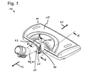
- Fig. 1 is a perspective view of the cleaning device 10th Fig. 2 is an illustration of the cleaning device 10 along the line AA Fig. 1 ,
- the cleaning device 10 has a surface cleaning element 11, which is designed as a wet cleaning nozzle for a vacuum cleaner, so as a vacuum cleaner nozzle for receiving dirt particles.
- the surface cleaning element 11 can be used for wet and dry cleaning of surfaces, eg of floor surfaces.
- a suction channel 17 is formed in each case, can be sucked through the loose dirt.
- a wiping surface is arranged, on which there is a wiper element 19 designed as a wipe.
- the wiping element 19 of the adhering to the surface to be cleaned dirt can be solved by the surface.
- the wiping element 19 is moistened with a cleaning fluid, for example water.
- the cleaning fluid is stored in a liquid container 15 disposed on the surface cleaning member 11, and can be transported to the wiping member 19 through a hose 13.
- the tube 13 first leads from the liquid container 15 to a valve 53 arranged on the surface cleaning element 11 in order to control the flow of the cleaning fluid through the tube.
- the hose 13 leads from the valve 53 to a pump 55 arranged on the surface cleaning element 11, through which the cleaning fluid can be promoted.
- the pump 55 is thus connected downstream of the valve 53 in the transport direction of the cleaning fluid.
- valve 53 of the pump 55 is connected downstream in the transport direction of the cleaning fluid.
- hose 13 carries the cleaning fluid from the valve 53 to the wiper element 19. The operations of the pump 55 and the valve 53 will be discussed in a paragraph below.
- the cleaning device 10 has a guide element 30, which comprises a connecting piece 31 and a suction tube with a handle.
- the connecting piece 31 and the suction pipe are connected to the suction channels 17.
- the connection piece 31 of the guide element 30 is shown in the figures.
- the user grasps the handle of the suction tube and thus the guide element 30.
- the user performs movements to move the surface cleaning element 11 in its main movement directions, namely in a forward direction 71 and to move a backward direction 73 over the surface to be cleaned.
- rollers 21 are arranged, which facilitate a movement in the forward direction 71 and backward direction 73, and whose axes are perpendicular to these two main directions of movement 71, 73.
- the guide element 30 is movably connected to the surface cleaning element 11 via a first 32, a second 33 and a third joint 37.
- the first 32 and second joint 33 which form a double joint 35, are designed as tilting joints arranged in succession with parallel joint axes.
- the axes of the first 32 and second joint 33 run during normal operation of the cleaning device 10, the example in Fig. 1 is shown, parallel to the surface to be cleaned and perpendicular to the main movement directions 71, 73.
- the third joint 37 is designed as a pivot joint, so that a rotatable connection stub 31 is formed.
- the third hinge 37 allows rotation of the guide member 30 with respect to the double hinge 35, allowing the user to more conveniently clean the floor under a bed, for example.
- the guide member 30 is movably connected via the third joint 37 with a second connecting element 43.
- the second connecting element 43 is connected via the second hinge 33 with a first connecting element 41 and this connected via the first joint 32 to the surface cleaning element 11 movable.
- the first joint 32 is arranged on the surface cleaning element 11 and the.
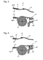
- FIG. 3 and 4 are a sectional view of the cleaning device 10 along the line BB Fig. 1 , Between the first connecting element 41 and the surface cleaning device 11, an elastic element 45 is arranged, through which the first connecting element 41 can be brought into a rest position with respect to the surface cleaning element 11.
- This rest position of the first connecting element 41 is in Fig. 3 shown.
- Fig. 4 a position deviating from the rest position is shown, in which the elastic element 45 exerts a restoring force on the first connecting element 41 in order to bring the first connecting element 41 into the rest position. If this restoring force does not counteract any greater force, the first connecting element 41 is brought into the rest position by the elastic element 45.
- the rest position is taken, for example, when the user turns off the cleaning device after use.
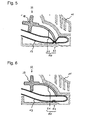
- FIGS. 5 and 6 the detail C turns off Fig. 2 shown.
- the valve 53 is shown, which is formed by a lever 51 and the hose 13.
- the valve 53 and the lever 51 are combined in a work implement 50 of the cleaning apparatus 10 so that the work implement 50 includes the lever 51 and the valve 53.
- This valve 53 is closed by the lever 51, the hose 13 as in Fig. 5 shown disconnected.
- the valve 53 is opened when the lever 51 the Hose 13 as in Fig. 6 shown free, so do not disconnect.
- Such a valve 53 is also referred to as a pinch valve.
- the lever 51 is arranged on a bearing journal 39 of the first connecting element 41, which lies in the articulation axis of the first articulation 32.
- FIGS. 7 and 8 show the pump 55, through which the cleaning fluid can be promoted.
- the pump 55 is part of the Häverrichters 50, so that the Schwarzter 50 also includes the pump 55.
- the pump 55 is not located, like the valve 53, in the right-hand part of the surface-cleaning element 11 viewed in the forward direction 71, but in the left-hand part of the surface-cleaning element 11 viewed in the forward direction 71.
- FIGS. 7 and 8 So do not show detail C.
- Fig. 2 that look like Fig. 1 can be seen on the right side, but show a detail corresponding to the detail C, which is located on the left side of the surface cleaning element 11.
- the pump 55 is actuated by a lever 51 which is arranged on a bearing journal 39 of the first connecting element 41.
- This bearing pin 39 is also located in the hinge axis of the first joint 31.
- the first connecting element 41 thus has a right and left bearing pin 39, on each of which a right and left lever 51 is arranged.
- the pump 55 is actuated by the lever 51, so that a work can be done by the Härichter 50. This work is performed due to a movement of the first articulation 32, so that upon a relative movement of the surface cleaning member 11 and the guide member 30 to each other the Häverrichter 50 can perform a work for actuating the pump 55.
- the cleaning fluid may flow from the hose 13 into a main pumping chamber 57.
- the volume of the main pumping chamber 57 becomes as in FIG Fig. 7 is reduced, so that the cleaning fluid accumulated in the main pumping chamber 57 is transported to the wiping member 19.
- the cleaning device 10 has two additional functions, namely, the pumping of the cleaning fluid by the pump 55 and the control of the flow of the cleaning fluid through the valve 53.
- no additional energy storage such as a spring is needed because the relative movement of guide member 30 and surface cleaning member 11 is used to each other to perform a work for actuating the valve 53 and the pump 55.
- the present invention makes it possible, with simple, constructive and cost-effective means, to provide an improved cleaning device which allows easy cleaning due to the movable connection between the guide element and allow the surface cleaning element.
- a cleaning device can be provided by the invention, which can use a movement during a cleaning process to allow an additional function.
Landscapes
- Engineering & Computer Science (AREA)
- Mechanical Engineering (AREA)
- Cleaning In General (AREA)
Applications Claiming Priority (1)
| Application Number | Priority Date | Filing Date | Title |
|---|---|---|---|
| DE102010030104A DE102010030104A1 (de) | 2010-06-15 | 2010-06-15 | Reinigungsgerät mit Flächenreinigungselement |
Publications (2)
| Publication Number | Publication Date |
|---|---|
| EP2397058A2 true EP2397058A2 (fr) | 2011-12-21 |
| EP2397058A3 EP2397058A3 (fr) | 2015-01-07 |
Family
ID=44508715
Family Applications (1)
| Application Number | Title | Priority Date | Filing Date |
|---|---|---|---|
| EP11169758.7A Withdrawn EP2397058A3 (fr) | 2010-06-15 | 2011-06-14 | Appareil de nettoyage avec élément de nettoyage de surfaces |
Country Status (2)
| Country | Link |
|---|---|
| EP (1) | EP2397058A3 (fr) |
| DE (1) | DE102010030104A1 (fr) |
Families Citing this family (2)
| Publication number | Priority date | Publication date | Assignee | Title |
|---|---|---|---|---|
| DE102012100457B4 (de) | 2012-01-20 | 2023-04-20 | Vorwerk & Co. Interholding Gmbh | Düse für einen Staubsauger |
| DE102019210557B3 (de) * | 2019-07-17 | 2020-11-26 | BSH Hausgeräte GmbH | Nassreinigungsvorrichtung mit einem rotierenden Wischelement |
Citations (3)
| Publication number | Priority date | Publication date | Assignee | Title |
|---|---|---|---|---|
| DE10025447A1 (de) | 2000-05-23 | 2001-11-29 | Bsh Bosch Siemens Hausgeraete | Reinigungsgerät |
| US6655866B1 (en) | 2002-07-12 | 2003-12-02 | Worldwide Integrated Resources, Inc. | Mop with pump action mechanism for dispensing liquid through an elevated spray nozzle |
| WO2008137414A2 (fr) | 2007-05-03 | 2008-11-13 | Johnsondiversey, Inc. | Outil et procédé d'entretien de plancher |
Family Cites Families (3)
| Publication number | Priority date | Publication date | Assignee | Title |
|---|---|---|---|---|
| NL287317A (fr) * | 1961-12-30 | |||
| US7650667B2 (en) * | 2006-07-31 | 2010-01-26 | Euro-Pro Operating, Llc | Actuator for steam mop |
| US8186973B2 (en) * | 2008-08-14 | 2012-05-29 | Euro-Pro Operating Llc | Tubular pump |
-
2010
- 2010-06-15 DE DE102010030104A patent/DE102010030104A1/de not_active Ceased
-
2011
- 2011-06-14 EP EP11169758.7A patent/EP2397058A3/fr not_active Withdrawn
Patent Citations (3)
| Publication number | Priority date | Publication date | Assignee | Title |
|---|---|---|---|---|
| DE10025447A1 (de) | 2000-05-23 | 2001-11-29 | Bsh Bosch Siemens Hausgeraete | Reinigungsgerät |
| US6655866B1 (en) | 2002-07-12 | 2003-12-02 | Worldwide Integrated Resources, Inc. | Mop with pump action mechanism for dispensing liquid through an elevated spray nozzle |
| WO2008137414A2 (fr) | 2007-05-03 | 2008-11-13 | Johnsondiversey, Inc. | Outil et procédé d'entretien de plancher |
Also Published As
| Publication number | Publication date |
|---|---|
| DE102010030104A1 (de) | 2011-12-15 |
| EP2397058A3 (fr) | 2015-01-07 |
Similar Documents
| Publication | Publication Date | Title |
|---|---|---|
| EP3206547B1 (fr) | Machine de nettoyage de surfaces | |
| EP3206550B1 (fr) | Machine de nettoyage de surfaces | |
| EP3206549B1 (fr) | Machine de nettoyage de surfaces dotée d'un dispositif d'humidification | |
| EP2470055B1 (fr) | Appareil de traitement de sol à guidage manuel | |
| DE102014114813A1 (de) | Flächen-Reinigungsmaschine und Verfahren zum Betreiben einer Flächen-Reinigungsmaschine | |
| DE202007017026U1 (de) | Bodenreinigungsgerät mit einer Reinigungswalze | |
| DE102017127131A1 (de) | Regenerierbarer Staubsauger | |
| EP3025626A1 (fr) | Buse de sol pour un appareil d'entretien du sol et procede de fabrication d'une buse de sol pour un appareil d'entretien du sol | |
| EP3547889A1 (fr) | Appareil de nettoyage et procédé de fonctionnement d'un appareil de nettoyage | |
| EP2587977B1 (fr) | Buse pour aspirateur | |
| DE102017208959A1 (de) | Düse für ein Bodenreinigungsgerät | |
| DE202013103571U1 (de) | Boden-Reinigungsmaschine | |
| EP2397058A2 (fr) | Appareil de nettoyage avec élément de nettoyage de surfaces | |
| DE102008008069A1 (de) | Bodenreinigungsgerät | |
| EP3185742A1 (fr) | Buse d'aspiration et appareil d'aspiration de surfaces dures | |
| DE202014000302U1 (de) | Reinigungsgerät | |
| DE102021119016A1 (de) | Bodenreinigungsvorrichtung | |
| EP3048943B1 (fr) | Suceur d'aspirateur pour appareil de nettoyage et appareil de nettoyage | |
| EP3981312B1 (fr) | Dispositif de nettoyage | |
| EP3133972A1 (fr) | Buse d'aspiration et appareil de nettoyage de surfaces dures | |
| EP1068830B1 (fr) | Appareil pour nettoyer les balais | |
| DE102019103651A1 (de) | Bodendüse für ein Reinigungsgerät mit Saugfunktion, Reinigungsgerät und Verfahren zum Absaugen eines Bodenbereichs | |
| EP3185743B1 (fr) | Buse d'aspiration et aspirateur pour surfaces dures | |
| DE10037082A1 (de) | Hochdruckreinigungsgerät für im wesentlichen ebene Flächen | |
| DE102008022178B4 (de) | Kanaluntersuchungssystem |
Legal Events
| Date | Code | Title | Description |
|---|---|---|---|
| AK | Designated contracting states |
Kind code of ref document: A2 Designated state(s): AL AT BE BG CH CY CZ DE DK EE ES FI FR GB GR HR HU IE IS IT LI LT LU LV MC MK MT NL NO PL PT RO RS SE SI SK SM TR |
|
| AX | Request for extension of the european patent |
Extension state: BA ME |
|
| PUAI | Public reference made under article 153(3) epc to a published international application that has entered the european phase |
Free format text: ORIGINAL CODE: 0009012 |
|
| RIC1 | Information provided on ipc code assigned before grant |
Ipc: A47L 9/06 20060101AFI20140812BHEP Ipc: A47L 13/22 20060101ALI20140812BHEP Ipc: A47L 11/40 20060101ALI20140812BHEP |
|
| PUAL | Search report despatched |
Free format text: ORIGINAL CODE: 0009013 |
|
| AK | Designated contracting states |
Kind code of ref document: A3 Designated state(s): AL AT BE BG CH CY CZ DE DK EE ES FI FR GB GR HR HU IE IS IT LI LT LU LV MC MK MT NL NO PL PT RO RS SE SI SK SM TR |
|
| AX | Request for extension of the european patent |
Extension state: BA ME |
|
| RIC1 | Information provided on ipc code assigned before grant |
Ipc: A47L 9/06 20060101AFI20141201BHEP Ipc: A47L 13/22 20060101ALI20141201BHEP Ipc: A47L 11/40 20060101ALI20141201BHEP |
|
| RAP1 | Party data changed (applicant data changed or rights of an application transferred) |
Owner name: BSH HAUSGERAETE GMBH |
|
| STAA | Information on the status of an ep patent application or granted ep patent |
Free format text: STATUS: THE APPLICATION IS DEEMED TO BE WITHDRAWN |
|
| 18D | Application deemed to be withdrawn |
Effective date: 20150708 |