EP2397231B2 - Procédé et dispositif d'application de colle sur des sections - Google Patents
Procédé et dispositif d'application de colle sur des sections Download PDFInfo
- Publication number
- EP2397231B2 EP2397231B2 EP11004562.2A EP11004562A EP2397231B2 EP 2397231 B2 EP2397231 B2 EP 2397231B2 EP 11004562 A EP11004562 A EP 11004562A EP 2397231 B2 EP2397231 B2 EP 2397231B2
- Authority
- EP
- European Patent Office
- Prior art keywords
- glue
- carrier
- valve
- channel
- valves
- Prior art date
- Legal status (The legal status is an assumption and is not a legal conclusion. Google has not performed a legal analysis and makes no representation as to the accuracy of the status listed.)
- Not-in-force
Links
- 239000003292 glue Substances 0.000 title claims description 188
- 238000004026 adhesive bonding Methods 0.000 claims description 8
- 239000012876 carrier material Substances 0.000 claims description 7
- 238000007789 sealing Methods 0.000 claims description 5
- 230000000903 blocking effect Effects 0.000 claims 3
- 230000000694 effects Effects 0.000 claims 3
- 230000000295 complement effect Effects 0.000 claims 1
- 230000037431 insertion Effects 0.000 claims 1
- 238000003780 insertion Methods 0.000 claims 1
- 238000007493 shaping process Methods 0.000 claims 1
- 238000009826 distribution Methods 0.000 description 16
- 230000005540 biological transmission Effects 0.000 description 2
- 235000019504 cigarettes Nutrition 0.000 description 2
- 238000010276 construction Methods 0.000 description 2
- 230000006735 deficit Effects 0.000 description 2
- 238000004519 manufacturing process Methods 0.000 description 2
- 210000000056 organ Anatomy 0.000 description 2
- HUWSZNZAROKDRZ-RRLWZMAJSA-N (3r,4r)-3-azaniumyl-5-[[(2s,3r)-1-[(2s)-2,3-dicarboxypyrrolidin-1-yl]-3-methyl-1-oxopentan-2-yl]amino]-5-oxo-4-sulfanylpentane-1-sulfonate Chemical compound OS(=O)(=O)CC[C@@H](N)[C@@H](S)C(=O)N[C@@H]([C@H](C)CC)C(=O)N1CCC(C(O)=O)[C@H]1C(O)=O HUWSZNZAROKDRZ-RRLWZMAJSA-N 0.000 description 1
- 230000015572 biosynthetic process Effects 0.000 description 1
- 238000006243 chemical reaction Methods 0.000 description 1
- 238000009434 installation Methods 0.000 description 1
- 239000000463 material Substances 0.000 description 1
- 238000012986 modification Methods 0.000 description 1
- 230000004048 modification Effects 0.000 description 1
- 238000004806 packaging method and process Methods 0.000 description 1
- 238000004382 potting Methods 0.000 description 1
- 238000009420 retrofitting Methods 0.000 description 1
- 239000000758 substrate Substances 0.000 description 1
- 239000013589 supplement Substances 0.000 description 1
- 230000007704 transition Effects 0.000 description 1
- 230000001960 triggered effect Effects 0.000 description 1
Images


Classifications
-
- B—PERFORMING OPERATIONS; TRANSPORTING
- B05—SPRAYING OR ATOMISING IN GENERAL; APPLYING FLUENT MATERIALS TO SURFACES, IN GENERAL
- B05C—APPARATUS FOR APPLYING FLUENT MATERIALS TO SURFACES, IN GENERAL
- B05C5/00—Apparatus in which liquid or other fluent material is projected, poured or allowed to flow on to the surface of the work
- B05C5/02—Apparatus in which liquid or other fluent material is projected, poured or allowed to flow on to the surface of the work the liquid or other fluent material being discharged through an outlet orifice by pressure, e.g. from an outlet device in contact or almost in contact, with the work
- B05C5/027—Coating heads with several outlets, e.g. aligned transversally to the moving direction of a web to be coated
- B05C5/0275—Coating heads with several outlets, e.g. aligned transversally to the moving direction of a web to be coated flow controlled, e.g. by a valve
- B05C5/0279—Coating heads with several outlets, e.g. aligned transversally to the moving direction of a web to be coated flow controlled, e.g. by a valve independently, e.g. individually, flow controlled
-
- B—PERFORMING OPERATIONS; TRANSPORTING
- B05—SPRAYING OR ATOMISING IN GENERAL; APPLYING FLUENT MATERIALS TO SURFACES, IN GENERAL
- B05C—APPARATUS FOR APPLYING FLUENT MATERIALS TO SURFACES, IN GENERAL
- B05C5/00—Apparatus in which liquid or other fluent material is projected, poured or allowed to flow on to the surface of the work
- B05C5/02—Apparatus in which liquid or other fluent material is projected, poured or allowed to flow on to the surface of the work the liquid or other fluent material being discharged through an outlet orifice by pressure, e.g. from an outlet device in contact or almost in contact, with the work
- B05C5/0291—Apparatus in which liquid or other fluent material is projected, poured or allowed to flow on to the surface of the work the liquid or other fluent material being discharged through an outlet orifice by pressure, e.g. from an outlet device in contact or almost in contact, with the work the material being discharged on the work through discrete orifices as discrete droplets, beads or strips that coalesce on the work or are spread on the work so as to form a continuous coating
Definitions
- the invention relates to a device for applying glue to carrier material having the features of the preambles of claims 1, 2, 3.
- glue unit is positioned stationary and the carrier material, in particular the blanks are moved past the glue unit, which are guaranteed due to precise control of metering, in particular of closure organs of Leimventile the exact delivery of Leimportionen and positionally accurate transfer to the substrate.
- the invention is intended to open up the possibility of being able to produce different glue images with a device having a plurality of glue outlets, in particular several glue valves, in accordance with the requirement due to the different design of blanks for packs.
- the invention has for its object to form a device for applying glue or a glue unit so that in a simple manner, a conversion can be done to produce different glue images on carrier material, in particular on blanks.
- a special feature of the invention is that a (not used because of Leimsentes) glue valve removed from the glue unit and replaced by a replacement piece or auxiliary piece, due to the design and arrangement of a particular common for all glue valves glue channel or distribution channel in the area the connection to the removed valve shuts off.
- the replacement piece / auxiliary piece is designed so that it - when arranged in the region of the removed glue valve - serves as a carrier for further functional means of the glue valve.
- a preferably leading to each glue valve electrical control line is positioned with end contact on the replacement piece / auxiliary piece, in particular fixed, without significant change in the relative position.
- An innovation relates to the structural design of the glue unit with the aim of easy assembly and removability of single or all glue valves. These are arranged on a preferably common carrier with a rail-like cross-sectional profile, in particular on the underside of the carrier positioned side by side and fastened by simple connection means, in particular by (two) screws. If a glue valve is removed, the replacement piece can be positioned in the same place and fixed with the same or the same connection means.
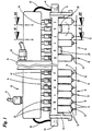
- a glue unit - is used for example for the transmission of glue portions or glue 10 on individual blanks 11 for the production of packages, especially folding boxes for cigarettes.
- glue points 10 there are several juxtaposed glue points 10 to be transferred to each blank 11.
- a complex glue picture ( EP 0 601 411 A2 ) consists of several adjacent rows of dots 12 per blank 11.
- each individual glue points 10 are shown by several adjacent rows of points 12 extending transversely to the plane of the drawing.
- the glue unit comprises a plurality of glue dispensers, in the present case glue valves 13.
- glue valves 13 are juxtaposed and mounted on a common carrier 14.
- the glue valves 13 are positioned so that the glue portions emitted by a valve nozzle 15, namely glue spots 10, exactly on the blank 11 are positioned.
- the glue valve 13 may, for example, substantially according to DE 10 2009 022 496.3 be formed, but with important modifications that facilitate the assembly and removal of the glue valve.
- the arrangement is such that the glue unit is positioned in a stationary manner with a plurality of glue valves 13 arranged next to one another above a movement or conveying path for the blanks 11.
- the blanks 11 transported at a short distance below the glue valves are provided with the respectively required glue pattern consisting of several rows of dots 12 by briefly opening the glue valves 13.
- the structure of the glue unit is chosen in this example so that the transverse support 14 is fixed in the glue station (a packaging machine) with connecting means, here with end flanges 16, to the construction of the machine.
- the glue unit according to Fig. 1 is geared towards two-lane operation. Accordingly, two groups of glue valves 13 are mounted on a common carrier 14, with two adjacent blanks 11 each being transported below the gluing unit (thus formed in a horizontal plane).
- the (six) glue valves 13 of the two working paths are with a to f on the one hand and g to I on the other hand in Fig. 1 characterized.
- glue valves of the glue unit are supplied with glue via a common glue line.
- this is designed as (transverse to the direction of movement of the blanks 11) extending distribution channel 17, preferably in the embodiment as a through hole in the carrier 14 with a suitable (circular) cross-section.
- the distribution channel 17, the glue via a central line (under pressure) is supplied.
- This is preferably connected centrally between the two groups of glue valves 13 with the distribution channel 17.
- the central line 18 connects to a central (upright) support piece 19, which is arranged between the two groups of glue valves 13 and connected to the carrier 14.
- a channel (or conduit) is arranged to connect the mouth of the central conduit 18 to the distribution channel 17.
- the distribution channel 17 is functionally composed of two sections which are supplied together with glue by the central line 18. Depending on a portion of the distribution channel 17 leads to the one and to the other group of glue valves 13 on the carrier 14.
- the (transverse) profile of the carrier 14 is formed so that a sufficiently sized distribution channel recording. For this purpose, an approximately square channel profile 20 (edge) on the carrier 14 is formed. In this runs the distribution channel 17, such that all glue valves 13 can be supplied with glue.
- the channel profile 20 is connected to a flat profile or a support flange 21 of the carrier 14 to form a uniform profile.
- the glue valves 13 are individually detachably connected to the support 14 in the region of the support flange 21.
- the glue valves 13 are arranged on the underside of the carrier 14 and fastened by screws 22, in the present case by two screws 22 to the carrier 14.
- the distribution channel 17 is connected to each glue valve 13 via at least one glue connection.
- a branch channel 23 is provided, which preferably leads as a bore from the distributor channel 17 to the glue valve 13 and adjoins an (upright) glue channel 24 within the glue valve 13.
- the glue valve 13 is positioned and the branch channel 23 is mounted so that the branch channel 23 with the glue channel 24 forms a continuous linear glue line, preferably due to matching dimensions without paragraphs or projections, so a continuous uniform channel up to a valve chamber.
- a seal is arranged, namely a sealing ring 46, which is preferably arranged on the glue valve 13, that is to say on the end region of the glue channel 24.
- the construction and operation of the glue valve correspond in principle to the glue valve DE 10 2009 022 496.3 ,
- the carrier 14 is adapted by further designs to an easy assembly and removal of the glue valves 13.
- One in the preferred used glue valves ( DE 10 2009 022 496.3 ) is arranged - approximately centrally located - on the upper side of the glue valve 13 to be operated adjusting screw 42. This occurs in the present embodiment of the carrier 14 through a recess formed in the support flange 21, which is presently designed as a threaded bore 41.
- the adjusting screw 42 is anchored with corresponding external thread in this threaded hole 41, with the possibility of adjustability of a valve member by means of this exposed adjusting screw 42nd
- FIG. 1 shows the example of the right working or the group of glue valves 13 g to I an embodiment in which two glue valves 13 - in the range of positions h and k - omitted or removed. Accordingly, fewer rows of dots 12 are transmitted accordingly.
- the position of the missing glue valve (s) 13 is supplied so that the operation for the remaining glue valves of the complete group as well as the subgroup with the glue valves g, i, j, l can continue unchanged and without impairment.
- the connection of the distribution channel 17 to the removed glue valve 13 or the glue channel 24 is to be closed first.
- a closure member is provided, preferably in the embodiment of a closure pin 25, which is inserted via the free (lower) side in the branch channel 23 and this closes.
- the closure pin 25 thus has the profile and the dimension of the branch channel 23.
- the closure pin 25 is formed so that a supplement of the cross-sectional profile of the distribution channel 24 takes place.
- the closure pin 25 is provided with a part-circular supplementary surface 26, which due to the shape and dimensions is flush with the (cylindrical) inner surface of the distribution channel 17 in the region of the branch channel 23.
- the glue can thereby be passed through the distribution channel 17 without affecting the flow.
- the closure member or the closure pin 25 is sealed against passage of material, in this case by a sealing ring 28 at the mouth of the branch channel 23rd
- the closure pin 25 is attached to a support member which is connected to the carrier 14 of the glue unit.
- the closure pin 25 is attached to a replacement piece 29, which is attached to the support 14 instead of the removed or missing glue valve 13, preferably by the same or by the same aids - screws 22 - with which the glue valve 13 is attached to the carrier 14.
- the replacement piece 29 is designed essentially as a web directed transversely to the carrier 14, at one end of which is anchored in a corresponding bore closure pin 25 is attached.
- the sealing ring 28 is arranged on the edge profile 20 facing (upper) surface.
- glue valve 13 - positions h and k in Fig. 1 - are more functional organs, which are preferably associated with each glue valve 13, temporarily or permanently secure.
- the control current is preferably supplied to the glue unit via a main line 31 common to all glue valves 13. At this close the individual control lines 30.
- the main line 31 opens into a distributor housing 32. In this connection with the individual control lines 30 is housed.
- the control line 30 passes through a passage opening 33 in a (lower) wall of the distributor housing 32 facing the glue valves 13.
- a short (upright) section of the control line 30 preferably leads in the downward direction to the associated glue valve 13.
- the control lines 30 are provided at their the glue valve 13 associated end with a connecting member, in this case with a plug 34 which is inserted into a trained for power transmission receptacle 35 in or on the housing of the glue valve 13.
- the end of the control line 30 and its plug 34 is held in the receptacle 35 by a nut 36 which is mounted on the plug 34 and cooperates with an external thread of the receptacle 35 on the glue valve 13.
- the plug receptacle 35 is due to the arrangement of the glue valve 13 and the dimension of the carrier 14 outside of the same range, so it is freely accessible by the support 14 without interference.
- the control line 30 together with the plug 34 remains substantially in the position and arrangement corresponding to the connection with a glue valve 13.
- the carrier 14 has a holding piece for the plug 34 with an external thread for the nut attached to the plug 34 36th
- the holding means for the plug 34 is attached to the replacement piece 29, that is on the holder for the closure pin 25.
- the web-shaped replacement piece 29 is provided with an extension.
- the support member for the plug 34 is attached.
- this is a screw bolt 37 which is inserted (from below) into the replacement piece 29 and fixed thereto by a nut 43.
- a plug 34 facing axial recess is formed at the free (upper) end of the screw bolt 37. This is adapted in shape and size to the end of the plug 34.
- the introduced into the recess 38 part of the plug 34 is fixed in this position by the nut 36, which is tuned to the external thread of the screw bolt 37.
- Some or all glue valves 13 are provided with a sensor, which is tuned to the respective gluing program or to the glue pattern. In case of incorrect assembly, so in a wrong replacement of a glue valve 13, an error signal is generated.
- a signal generator 39 is arranged on the replacement piece 29 and effective to trigger an error signal when a replacement piece 29 has been mounted in the wrong place or has failed to remove a glue valve and replace it with a replacement piece 29.
- the signal generator 39 is designed as an electrical aid, namely as an ohmic resistance or as a capacitive load.
- the replacement piece 29 If, however, with the glue valve removed, the replacement piece 29 correctly positioned, but the plug 34 is not seated in the receptacle 35, a faulty (infinite) resistance measured and thus also triggered an error message.
- the signal transmitter 39 or the resistor is arranged in the recess 38 of the bolt 37 and fixed by a potting compound 40. By inserting the plug 34 into the recess 38, the contact with the signal generator 39 or resistance is established.
- the pressure in the glue system is checked by pressure sensors 44. These are preferably arranged at both ends of the distributor channel 17 extending over the full length of the carrier 14.
- the pressure sensors 44 are connected via measuring lines 45 to the electrical control system in the distributor housing 32, such that when a pressure drop in the distribution channel 17, a corresponding signal is generated.
Landscapes
- Coating Apparatus (AREA)
Claims (11)
- Dispositif d'application de colle sur un matériau de support, en particulier sur des pièces découpées (11) pour la fabrication de paquets, au moyen d'un dispositif d'encollage qui présente une pluralité de vannes d'encollage (13) disposées de préférence les unes à côté des autres et retenues par un support (14), auxquelles de la colle peut être acheminée par le biais de conduites de colle conduisant à chaque vanne d'encollage (13), caractérisé par les caractéristiques suivantes :a) toutes les vannes d'encollage ou des vannes d'encollage individuelles (13) sont montées de manière à pouvoir être enlevées sur un support de préférence commun (14) du dispositif d'encollage,b) pour la mise hors service temporaire d'une ou de plusieurs vannes d'encollage (13), la vanne d'encollage concernée peut être enlevée du support (14),c) une pièce de remplacement (29) peut être montée sur le support (13) à la place de la vanne d'encollage enlevée (13),d) la pièce de remplacement (29) est pourvue d'un organe de fermeture pour un canal de distribution (17) pour l'alimentation en colle et/ou, pour un canal de dérivation (23) se raccordant au canal de distribution (17) et conduisant à la vanne d'encollage (13), qui, lors du positionnement de la pièce de remplacement (29) sur le support (13), réalise le blocage,e) l'organe de fermeture (25), en raison de sa forme correspondante, notamment du fait d'une surface complémentaire cintrée (26), est réalisé de telle sorte que dans la position de fermeture dans le canal de dérivation (23) une paroi interne ou une surface interne du canal de distribution (17) soit complétée par engagement par correspondance de forme, sans gradin, dans la région de l'organe de fermeture (25).
- Dispositif d'application de colle sur un matériau de support, en particulier sur des pièces découpées (11) pour la fabrication de paquets, au moyen d'un dispositif d'encollage qui présente une pluralité de vannes d'encollage (13) disposées de préférence les unes à côté des autres et retenues par un support (14), auxquelles de la colle peut être acheminée par le biais de conduites de colle conduisant à chaque vanne d'encollage (13), caractérisé par les caractéristiques suivantes :a) toutes les vannes d'encollage ou des vannes d'encollage individuelles (13) sont montées de manière à pouvoir être enlevées sur un support de préférence commun (14) du dispositif d'encollage,b) pour la mise hors service temporaire d'une ou de plusieurs vannes d'encollage (13), la vanne d'encollage concernée peut être enlevée du support (14),c) une pièce de remplacement (29) peut être montée sur le support (13) à la place de la vanne d'encollage enlevée (13),d) a pièce de remplacement (29) est pourvue d'un organe de fermeture pour un canal de distribution (17) pour alimentation en colle et/ou pour un canal de dérivation (23) se raccordant au canal de distribution (17) et conduisant à la vanne d'encollage (13), qui, lors du positionnement de la pièce de remplacement (29) sur le support (13), réalise le blocage,e) la pièce de remplacement (29) est réalisée sous forme de nervure, s'étend transversalement par rapport au support (14) et est montée de préférence en dessous de celui-ci, une région d'extrémité libre faisant saillie au-delà du support (14) présentant des logements ou des éléments de retenue pour d'autres organes fonctionnels de la vanne d'encollage (13), en particulier un logement ou un élément de retenue pour une extrémité libre - connecteur (34) - d'une conduite de commande (électrique) (30).
- Dispositif d'application de colle sur un matériau de support, en particulier sur des pièces découpées (11) pour la fabrication de paquets, au moyen d'un dispositif d'encollage qui présente une pluralité de vannes d'encollage (13) disposées de préférence les unes à côté des autres et retenues par un support (14), auxquelles de la colle peut être acheminée par le biais de conduites de colle conduisant à chaque vanne d'encollage (13), caractérisé par les caractéristiques suivantes :a) toutes les vannes d'encollage ou des vannes d'encollage individuelles (13) sont montées de manière à pouvoir être enlevées sur un support de préférence commun (14) du dispositif d'encollage,b) pour la mise hors service temporaire d'une ou de plusieurs vannes d'encollage (13), la vanne d'encollage concernée peut être enlevée du support (14),c) une pièce de remplacement (29) peut être montée sur le support (13) à la place de la vanne d'encollage enlevée (13),d) la pièce de remplacement (29) est pourvue d'un organe de fermeture pour un canal de distribution (17) pour l'alimentation en colle et/ou pour un canal de dérivation (23) se raccordant au canal de distribution (17) et conduisant à la vanne d'encollage (13), qui, lors du positionnement de la pièce de remplacement (29) sur le support (13), réalise le blocage,e) au moins un capteur est associé à chaque vanne d'encollage (13), lequel réagit à des remplacements défectueux ou absents de vannes d'encollage (13) et produit un signal d'erreur, un capteur de signal (39) étant de préférence disposé dans le renfoncement (38) d'un boulon fileté (37) de chaque pièce de remplacement (29), lequel coopère avec le connecteur (34) de la conduite de commande (30), en particulier présente une résistance différente de la résistance d'une bobine électrique de la vanne d'encollage et réagit par le biais de la conduite de commande (13) à une résistance coïncidente ou à des différences de résistance.
- Dispositif selon la revendication 1, 2 ou 3, caractérisé en ce que la pièce de remplacement (29), après l'enlèvement d'une vanne d'encollage (13), est fixée essentiellement dans la position de la vanne d'encollage (13) sur le support (14), de préférence avec les mêmes moyens de connexion ou des moyens de connexion identiques à ceux utilisés pour la vanne d'encollage (13) - des vis (22).
- Dispositif selon la revendication 1, 2, 3 ou 4, caractérisé en ce qu'un tourillon de fermeture (25) est disposé du côté (supérieur) de la pièce de remplacement (29) associé au canal de dérivation (23) de telle sorte que lors du positionnement de la pièce de remplacement (29) sur le support (14), le tourillon de fermeture (25) soit positionné dans la position de fermeture à l'intérieur du canal de dérivation (23).
- Dispositif selon la revendication 1, 2, 3 ou selon l'une quelconque des autres revendications, caractérisé en ce que le tourillon de fermeture (25) est étanchéifié dans la position de fermeture par rapport à l'intérieur du canal de distribution (17), en particulier par une bague d'étanchéité (28) disposée sur la pièce de remplacement (29), entourant le tourillon de fermeture (25) au niveau d'un côté (supérieur) tourné vers le support (14).
- Dispositif selon la revendication 2 ou selon l'une quelconque des autres revendications, caractérisé en ce que le logement monté sur la pièce de remplacement (29) pour le connecteur terminal (34) de la conduite de commande (30) présente un renfoncement ouvert vers le haut (38) pour l'insertion du connecteur (34) ou d'une partie de celui-ci, le renfoncement (38) étant de préférence formé dans un boulon fileté dressé (37) et le connecteur (34) étant fixé dans le renfoncement (38) par un sur-écrou (36).
- Dispositif selon la revendication 1, 2, 3 ou selon l'une quelconque des autres revendications, caractérisé en ce que le support (14) de préférence fixé aux deux extrémités par des bridges de support (21) présente un élargissement de profile pour recevoir le canal de distribution réalisé sous forme d'alésage continu, en particulier un profilé en forme de canal (20), auquel se raccorde une bride de support (21), le support (14) présentant des alésages pour le raccordement de la vanne d'encollage (13), en particulier un alésage fileté (41) pour une vis de réglage (42) et pour des (deux) vis (22) pour la fixation de la vanne d'encollage (13) au support (14).
- Dispositif selon la revendication 1, 2, 3 ou selon l'une quelconque des autres revendications, caractérisé en ce que la vanne d'encollage (13) présente un canal de colle de préférence dressé (24) qui débouche dans la région du canal de dérivation (23) pour l'alimentation en colle et qui se termine en affleurement avec le canal de dérivation (23) de telle sorte qu'une conduite de colle soit formée depuis le canal de distribution (17) par le biais du canal de dérivation (23) et du canal de colle (24) jusqu'à une chambre de vanne, de préférence une bague d'étanchéité (46) entourant l'embouchure du canal de colle (24) étant disposée au niveau de la vanne d'encollage (13).
- Dispositif selon la revendication 1, 2, 3 ou selon l'une quelconque des autres revendications, caractérise en ce que le raccord pour la conduite de commande (30) à la vanne d'encollage (13), notamment un logement (35) pour un connecteur (34) de la conduite de commande (30), est disposé de manière librement accessible à l'extérieur de la région du support (14).
- Dispositif selon la revendication 1, 2, 3 ou selon l'une quelconque des autres revendications, caractérisé en ce qu'une conduite principale (31) pour l'alimentation électrique des conduites de commande (30) se raccorde à un boîtier de distribution (32) orienté transversalement, de préférence allongé, depuis lequel partent des conduites de commande individuelles (30) allant aux vannes d'encollage (13).
Priority Applications (1)
| Application Number | Priority Date | Filing Date | Title |
|---|---|---|---|
| PL11004562T PL2397231T5 (pl) | 2010-06-18 | 2011-06-04 | Sposób i urządzenie do nanoszenia kleju na wykroje |
Applications Claiming Priority (1)
| Application Number | Priority Date | Filing Date | Title |
|---|---|---|---|
| DE102010024361A DE102010024361A1 (de) | 2010-06-18 | 2010-06-18 | Verfahren und Vorrichtung zum Auftragen von Leim auf Zuschnitte |
Publications (3)
| Publication Number | Publication Date |
|---|---|
| EP2397231A1 EP2397231A1 (fr) | 2011-12-21 |
| EP2397231B1 EP2397231B1 (fr) | 2014-08-13 |
| EP2397231B2 true EP2397231B2 (fr) | 2018-04-11 |
Family
ID=44785081
Family Applications (1)
| Application Number | Title | Priority Date | Filing Date |
|---|---|---|---|
| EP11004562.2A Not-in-force EP2397231B2 (fr) | 2010-06-18 | 2011-06-04 | Procédé et dispositif d'application de colle sur des sections |
Country Status (3)
| Country | Link |
|---|---|
| EP (1) | EP2397231B2 (fr) |
| DE (1) | DE102010024361A1 (fr) |
| PL (1) | PL2397231T5 (fr) |
Cited By (2)
| Publication number | Priority date | Publication date | Assignee | Title |
|---|---|---|---|---|
| CN110639828A (zh) * | 2019-09-11 | 2020-01-03 | 西南科技大学 | 多层分类法的卷烟条烟多规格一体化分拣方法 |
| CN111071557A (zh) * | 2019-12-28 | 2020-04-28 | 合肥禄正新能源科技有限公司 | 一种obc+dcdc一体机的包装设备 |
Families Citing this family (8)
| Publication number | Priority date | Publication date | Assignee | Title |
|---|---|---|---|---|
| DE202013100352U1 (de) * | 2013-01-25 | 2014-04-28 | Baumer Hhs Gmbh | Auftragseinrichtung zum Auftrag von fluidem Medium auf ein Substrat |
| CN106563617B (zh) * | 2016-11-15 | 2018-10-09 | 安徽养和医疗器械设备有限公司 | 一种用于呼吸卡涂液装置 |
| DE102017207851B4 (de) * | 2017-05-10 | 2023-02-16 | Audi Ag | Vorrichtung und Verfahren zum Auftragen von flüssigem Klebstoff |
| CN107930985B (zh) * | 2017-12-04 | 2021-01-26 | 芜湖华烨新材料有限公司 | 一种上胶装置 |
| CN108405263B (zh) * | 2018-05-09 | 2024-07-02 | 苏州丰川电子科技有限公司 | 用于高精密笔记本上盖冲压件的加工装置 |
| CN113385368A (zh) * | 2021-05-13 | 2021-09-14 | 广东科杰机械自动化有限公司 | 多头喷胶装置、喷胶设备及喷胶方法 |
| DE102023128194A1 (de) * | 2023-10-16 | 2025-04-17 | Khs Gmbh | Verteileinheit für eine Applikationseinrichtung, Applikationseinrichtung mit einer entsprechenden Verteileinheit, Beleimungsstation mit einer Vielzahl von Applikationseinrichtungen und Verfahren zum additiven Fertigen einer Verteileinheit |
| CN117543064B (zh) * | 2024-01-08 | 2024-04-02 | 深圳市铭镭激光设备有限公司 | 一种新能源电池模组全自动生产线 |
Citations (5)
| Publication number | Priority date | Publication date | Assignee | Title |
|---|---|---|---|---|
| US3135628A (en) † | 1961-05-11 | 1964-06-02 | Sunkist Growers Inc | Apparatus for coating with adhesive or other fluent materials |
| US3298353A (en) † | 1963-09-03 | 1967-01-17 | Hamilton Tool Co | Multiple orifice glue applicator |
| DE3506393A1 (de) † | 1985-02-23 | 1986-08-28 | Windmöller & Hölscher, 4540 Lengerich | Leimauftragsvorrichtung |
| US4744330A (en) † | 1985-12-04 | 1988-05-17 | Claassen Henning J | Device for intermittent application of liquids such as adhesive |
| EP0410400B1 (fr) † | 1989-07-28 | 1993-11-03 | PLANATOL - Klebetechnik Gesellschaft mit beschränkter Haftung | Dispositif pour l'alimentation en matériau de plieuses et dispositifs de mouillage dans des machines à imprimer |
Family Cites Families (13)
| Publication number | Priority date | Publication date | Assignee | Title |
|---|---|---|---|---|
| US4488665A (en) * | 1982-05-24 | 1984-12-18 | Spraymation, Inc. | Multiple-outlet adhesive applicator apparatus and method |
| US5172833A (en) * | 1992-01-09 | 1992-12-22 | Slautterback Corporation | Modular applicator having a separate flow loop to prevent stagnant regions |
| DE9201387U1 (de) * | 1992-02-05 | 1992-05-21 | Bierther, Hans-Dietmar, 6200 Wiesbaden | Auftragskopf |
| DE4241176B4 (de) | 1992-12-08 | 2005-12-22 | Focke & Co.(Gmbh & Co. Kg) | Vorrichtung zum Auftragen von Leim auf Zuschnitte für Klappschachteln |
| DE9310427U1 (de) * | 1993-07-13 | 1994-11-10 | ITW Dynatec GmbH Klebetechnik, 40699 Erkrath | Vorrichtung zur Zufuhr von Schmelzklebstoffen o.dgl. zu einer mehrere Auftragsköpfe umfassenden Auftragsvorrichtung |
| US5875922A (en) * | 1997-10-10 | 1999-03-02 | Nordson Corporation | Apparatus for dispensing an adhesive |
| US6012503A (en) * | 1997-11-26 | 2000-01-11 | Riverwood International Corporation | Adjustable gluing apparatus for a packaging machine |
| DE10327646B4 (de) * | 2002-09-13 | 2007-07-12 | Windmöller & Hölscher Kg | Vorrichtung zur Bildung eines Leimprofils für Kreuzbodensäcke |
| DE10303285A1 (de) * | 2003-01-28 | 2004-08-05 | Focke Gmbh & Co. Kg | Verfahren und Vorrichtung zum Beleimen von Verpackungsmaterial |
| US20050015050A1 (en) * | 2003-07-15 | 2005-01-20 | Kimberly-Clark Worldwide, Inc. | Apparatus for depositing fluid material onto a substrate |
| DE102008027259A1 (de) * | 2008-06-06 | 2009-12-17 | Focke & Co.(Gmbh & Co. Kg) | Verfahren und Vorrichtung zur Herstellung von Zigarettenpackungen |
| DE102009022496A1 (de) | 2009-05-25 | 2011-01-05 | Focke & Co.(Gmbh & Co. Kg) | Ventil, insbesondere Leimventil |
| DE102009034687B4 (de) * | 2009-07-24 | 2017-03-30 | Windmöller & Hölscher Kg | Vorrichtung und Verfahren zum Versehen von Werkstücken oder Bahnen mit Leim |
-
2010
- 2010-06-18 DE DE102010024361A patent/DE102010024361A1/de not_active Withdrawn
-
2011
- 2011-06-04 EP EP11004562.2A patent/EP2397231B2/fr not_active Not-in-force
- 2011-06-04 PL PL11004562T patent/PL2397231T5/pl unknown
Patent Citations (5)
| Publication number | Priority date | Publication date | Assignee | Title |
|---|---|---|---|---|
| US3135628A (en) † | 1961-05-11 | 1964-06-02 | Sunkist Growers Inc | Apparatus for coating with adhesive or other fluent materials |
| US3298353A (en) † | 1963-09-03 | 1967-01-17 | Hamilton Tool Co | Multiple orifice glue applicator |
| DE3506393A1 (de) † | 1985-02-23 | 1986-08-28 | Windmöller & Hölscher, 4540 Lengerich | Leimauftragsvorrichtung |
| US4744330A (en) † | 1985-12-04 | 1988-05-17 | Claassen Henning J | Device for intermittent application of liquids such as adhesive |
| EP0410400B1 (fr) † | 1989-07-28 | 1993-11-03 | PLANATOL - Klebetechnik Gesellschaft mit beschränkter Haftung | Dispositif pour l'alimentation en matériau de plieuses et dispositifs de mouillage dans des machines à imprimer |
Cited By (3)
| Publication number | Priority date | Publication date | Assignee | Title |
|---|---|---|---|---|
| CN110639828A (zh) * | 2019-09-11 | 2020-01-03 | 西南科技大学 | 多层分类法的卷烟条烟多规格一体化分拣方法 |
| CN110639828B (zh) * | 2019-09-11 | 2021-09-21 | 西南科技大学 | 多层分类法的卷烟条烟多规格一体化分拣方法 |
| CN111071557A (zh) * | 2019-12-28 | 2020-04-28 | 合肥禄正新能源科技有限公司 | 一种obc+dcdc一体机的包装设备 |
Also Published As
| Publication number | Publication date |
|---|---|
| EP2397231B1 (fr) | 2014-08-13 |
| PL2397231T5 (pl) | 2018-08-31 |
| PL2397231T3 (pl) | 2015-02-27 |
| DE102010024361A1 (de) | 2011-12-22 |
| EP2397231A1 (fr) | 2011-12-21 |
Similar Documents
| Publication | Publication Date | Title |
|---|---|---|
| EP2397231B2 (fr) | Procédé et dispositif d'application de colle sur des sections | |
| EP0601411B1 (fr) | Procédé et dispositif pour appliquer de la colle sur des flans pour boîtes à charnière | |
| EP0920919B1 (fr) | Boíte à couvercle articulé pour cigarettes et méthode et appareil pour l'encollage de matériau d'emballage | |
| EP2363359B1 (fr) | Convoyeur avec un guide | |
| EP0727357B1 (fr) | Machine de formage, de remplissage et de scellement opérant de façon aseptique | |
| EP3104981A2 (fr) | Ensemble de vannes de dépôt de milieux fluides sur des surfaces | |
| WO2012139907A1 (fr) | Dispositif d'ajustement de formats | |
| DE102010039133A1 (de) | Halterungsanordnung zur Halterung von Systemen sowie Luft- oder Raumfahrzeug | |
| WO2022223377A1 (fr) | Module de dosage | |
| DE3509711C2 (de) | Vorrichtung zur Zufuhr von Zigaretten zur Umhüllungsstrecke einer Verpackungsmaschine | |
| EP2948382B1 (fr) | Dispositif pour etaler un liquide sur un substrat | |
| DE60001034T2 (de) | Vorrichtung zum Zuführen von Tabletten in einer Verpackungsmaschine | |
| EP2354563B1 (fr) | Agencement de vannes | |
| DE102006028815B3 (de) | Verfahren zur Herstellung eines elektrischen Hybridbauteils | |
| DE4115544A1 (de) | Einheit zum zufuehren von produkten zu einer herstellungsmaschine | |
| EP1975072A1 (fr) | Dispositif d'alimentation | |
| DE102015106861B4 (de) | Vorrichtung zum Etikettieren von einzelnen Produkten | |
| EP0930130B1 (fr) | Dispositif de serrage | |
| EP0681545A1 (fr) | Dispositif permettant de verifier des cigarettes. | |
| EP3044100A1 (fr) | Pièce de format et fixations pour pièces de format | |
| EP1937560B1 (fr) | Dispositif d'étiquetage de pots formés dans une bande de matériau d'emballage | |
| EP2239469A2 (fr) | Agencement de vannes | |
| DE29905345U1 (de) | Vorrichtung zur dosierten Abgabe von strömenden Medien | |
| DE102017105013B4 (de) | Tintenstrahldrucker für die Beschriftung von Waren mit einem Schreibkopf, einem Vorratsbehälter und einer Halteeinrichtung | |
| WO2025082817A1 (fr) | Unité de distribution pour un dispositif d'application, dispositif d'application doté d'une unité de distribution correspondante, poste d'encollage doté d'une pluralité de dispositifs d'application, dispositif de formation de contenants d'emballage et procédé de fabrication additive d'une unité de distribution |
Legal Events
| Date | Code | Title | Description |
|---|---|---|---|
| AK | Designated contracting states |
Kind code of ref document: A1 Designated state(s): AL AT BE BG CH CY CZ DE DK EE ES FI FR GB GR HR HU IE IS IT LI LT LU LV MC MK MT NL NO PL PT RO RS SE SI SK SM TR |
|
| AX | Request for extension of the european patent |
Extension state: BA ME |
|
| PUAI | Public reference made under article 153(3) epc to a published international application that has entered the european phase |
Free format text: ORIGINAL CODE: 0009012 |
|
| 17P | Request for examination filed |
Effective date: 20111128 |
|
| RIC1 | Information provided on ipc code assigned before grant |
Ipc: B05C 5/02 20060101AFI20131204BHEP |
|
| GRAP | Despatch of communication of intention to grant a patent |
Free format text: ORIGINAL CODE: EPIDOSNIGR1 |
|
| INTG | Intention to grant announced |
Effective date: 20140213 |
|
| GRAS | Grant fee paid |
Free format text: ORIGINAL CODE: EPIDOSNIGR3 |
|
| GRAA | (expected) grant |
Free format text: ORIGINAL CODE: 0009210 |
|
| AK | Designated contracting states |
Kind code of ref document: B1 Designated state(s): AL AT BE BG CH CY CZ DE DK EE ES FI FR GB GR HR HU IE IS IT LI LT LU LV MC MK MT NL NO PL PT RO RS SE SI SK SM TR |
|
| REG | Reference to a national code |
Ref country code: GB Ref legal event code: FG4D Free format text: NOT ENGLISH |
|
| REG | Reference to a national code |
Ref country code: AT Ref legal event code: REF Ref document number: 681872 Country of ref document: AT Kind code of ref document: T Effective date: 20140815 Ref country code: CH Ref legal event code: EP |
|
| REG | Reference to a national code |
Ref country code: IE Ref legal event code: FG4D Free format text: LANGUAGE OF EP DOCUMENT: GERMAN |
|
| REG | Reference to a national code |
Ref country code: DE Ref legal event code: R096 Ref document number: 502011004001 Country of ref document: DE Effective date: 20140925 |
|
| REG | Reference to a national code |
Ref country code: NL Ref legal event code: VDEP Effective date: 20140813 |
|
| REG | Reference to a national code |
Ref country code: LT Ref legal event code: MG4D |
|
| PG25 | Lapsed in a contracting state [announced via postgrant information from national office to epo] |
Ref country code: NO Free format text: LAPSE BECAUSE OF FAILURE TO SUBMIT A TRANSLATION OF THE DESCRIPTION OR TO PAY THE FEE WITHIN THE PRESCRIBED TIME-LIMIT Effective date: 20141113 Ref country code: BG Free format text: LAPSE BECAUSE OF FAILURE TO SUBMIT A TRANSLATION OF THE DESCRIPTION OR TO PAY THE FEE WITHIN THE PRESCRIBED TIME-LIMIT Effective date: 20141113 Ref country code: LT Free format text: LAPSE BECAUSE OF FAILURE TO SUBMIT A TRANSLATION OF THE DESCRIPTION OR TO PAY THE FEE WITHIN THE PRESCRIBED TIME-LIMIT Effective date: 20140813 Ref country code: SE Free format text: LAPSE BECAUSE OF FAILURE TO SUBMIT A TRANSLATION OF THE DESCRIPTION OR TO PAY THE FEE WITHIN THE PRESCRIBED TIME-LIMIT Effective date: 20140813 Ref country code: GR Free format text: LAPSE BECAUSE OF FAILURE TO SUBMIT A TRANSLATION OF THE DESCRIPTION OR TO PAY THE FEE WITHIN THE PRESCRIBED TIME-LIMIT Effective date: 20141114 Ref country code: ES Free format text: LAPSE BECAUSE OF FAILURE TO SUBMIT A TRANSLATION OF THE DESCRIPTION OR TO PAY THE FEE WITHIN THE PRESCRIBED TIME-LIMIT Effective date: 20140813 Ref country code: PT Free format text: LAPSE BECAUSE OF FAILURE TO SUBMIT A TRANSLATION OF THE DESCRIPTION OR TO PAY THE FEE WITHIN THE PRESCRIBED TIME-LIMIT Effective date: 20141215 Ref country code: FI Free format text: LAPSE BECAUSE OF FAILURE TO SUBMIT A TRANSLATION OF THE DESCRIPTION OR TO PAY THE FEE WITHIN THE PRESCRIBED TIME-LIMIT Effective date: 20140813 |
|
| PG25 | Lapsed in a contracting state [announced via postgrant information from national office to epo] |
Ref country code: RS Free format text: LAPSE BECAUSE OF FAILURE TO SUBMIT A TRANSLATION OF THE DESCRIPTION OR TO PAY THE FEE WITHIN THE PRESCRIBED TIME-LIMIT Effective date: 20140813 Ref country code: LV Free format text: LAPSE BECAUSE OF FAILURE TO SUBMIT A TRANSLATION OF THE DESCRIPTION OR TO PAY THE FEE WITHIN THE PRESCRIBED TIME-LIMIT Effective date: 20140813 Ref country code: IS Free format text: LAPSE BECAUSE OF FAILURE TO SUBMIT A TRANSLATION OF THE DESCRIPTION OR TO PAY THE FEE WITHIN THE PRESCRIBED TIME-LIMIT Effective date: 20141213 Ref country code: CY Free format text: LAPSE BECAUSE OF FAILURE TO SUBMIT A TRANSLATION OF THE DESCRIPTION OR TO PAY THE FEE WITHIN THE PRESCRIBED TIME-LIMIT Effective date: 20140813 Ref country code: HR Free format text: LAPSE BECAUSE OF FAILURE TO SUBMIT A TRANSLATION OF THE DESCRIPTION OR TO PAY THE FEE WITHIN THE PRESCRIBED TIME-LIMIT Effective date: 20140813 |
|
| REG | Reference to a national code |
Ref country code: PL Ref legal event code: T3 |
|
| PG25 | Lapsed in a contracting state [announced via postgrant information from national office to epo] |
Ref country code: NL Free format text: LAPSE BECAUSE OF FAILURE TO SUBMIT A TRANSLATION OF THE DESCRIPTION OR TO PAY THE FEE WITHIN THE PRESCRIBED TIME-LIMIT Effective date: 20140813 |
|
| PG25 | Lapsed in a contracting state [announced via postgrant information from national office to epo] |
Ref country code: DK Free format text: LAPSE BECAUSE OF FAILURE TO SUBMIT A TRANSLATION OF THE DESCRIPTION OR TO PAY THE FEE WITHIN THE PRESCRIBED TIME-LIMIT Effective date: 20140813 Ref country code: RO Free format text: LAPSE BECAUSE OF FAILURE TO SUBMIT A TRANSLATION OF THE DESCRIPTION OR TO PAY THE FEE WITHIN THE PRESCRIBED TIME-LIMIT Effective date: 20140813 Ref country code: SK Free format text: LAPSE BECAUSE OF FAILURE TO SUBMIT A TRANSLATION OF THE DESCRIPTION OR TO PAY THE FEE WITHIN THE PRESCRIBED TIME-LIMIT Effective date: 20140813 Ref country code: EE Free format text: LAPSE BECAUSE OF FAILURE TO SUBMIT A TRANSLATION OF THE DESCRIPTION OR TO PAY THE FEE WITHIN THE PRESCRIBED TIME-LIMIT Effective date: 20140813 Ref country code: CZ Free format text: LAPSE BECAUSE OF FAILURE TO SUBMIT A TRANSLATION OF THE DESCRIPTION OR TO PAY THE FEE WITHIN THE PRESCRIBED TIME-LIMIT Effective date: 20140813 |
|
| REG | Reference to a national code |
Ref country code: DE Ref legal event code: R026 Ref document number: 502011004001 Country of ref document: DE |
|
| PLBI | Opposition filed |
Free format text: ORIGINAL CODE: 0009260 |
|
| 26 | Opposition filed |
Opponent name: G.D S.P.A. Effective date: 20150511 |
|
| PLAX | Notice of opposition and request to file observation + time limit sent |
Free format text: ORIGINAL CODE: EPIDOSNOBS2 |
|
| PLAF | Information modified related to communication of a notice of opposition and request to file observations + time limit |
Free format text: ORIGINAL CODE: EPIDOSCOBS2 |
|
| PG25 | Lapsed in a contracting state [announced via postgrant information from national office to epo] |
Ref country code: SI Free format text: LAPSE BECAUSE OF FAILURE TO SUBMIT A TRANSLATION OF THE DESCRIPTION OR TO PAY THE FEE WITHIN THE PRESCRIBED TIME-LIMIT Effective date: 20140813 |
|
| PLBB | Reply of patent proprietor to notice(s) of opposition received |
Free format text: ORIGINAL CODE: EPIDOSNOBS3 |
|
| PG25 | Lapsed in a contracting state [announced via postgrant information from national office to epo] |
Ref country code: MC Free format text: LAPSE BECAUSE OF FAILURE TO SUBMIT A TRANSLATION OF THE DESCRIPTION OR TO PAY THE FEE WITHIN THE PRESCRIBED TIME-LIMIT Effective date: 20140813 |
|
| REG | Reference to a national code |
Ref country code: CH Ref legal event code: PL |
|
| PG25 | Lapsed in a contracting state [announced via postgrant information from national office to epo] |
Ref country code: LU Free format text: LAPSE BECAUSE OF FAILURE TO SUBMIT A TRANSLATION OF THE DESCRIPTION OR TO PAY THE FEE WITHIN THE PRESCRIBED TIME-LIMIT Effective date: 20150604 |
|
| REG | Reference to a national code |
Ref country code: IE Ref legal event code: MM4A |
|
| REG | Reference to a national code |
Ref country code: FR Ref legal event code: ST Effective date: 20160229 |
|
| PG25 | Lapsed in a contracting state [announced via postgrant information from national office to epo] |
Ref country code: LI Free format text: LAPSE BECAUSE OF NON-PAYMENT OF DUE FEES Effective date: 20150630 Ref country code: CH Free format text: LAPSE BECAUSE OF NON-PAYMENT OF DUE FEES Effective date: 20150630 Ref country code: IE Free format text: LAPSE BECAUSE OF NON-PAYMENT OF DUE FEES Effective date: 20150604 |
|
| PG25 | Lapsed in a contracting state [announced via postgrant information from national office to epo] |
Ref country code: FR Free format text: LAPSE BECAUSE OF NON-PAYMENT OF DUE FEES Effective date: 20150630 |
|
| PG25 | Lapsed in a contracting state [announced via postgrant information from national office to epo] |
Ref country code: MT Free format text: LAPSE BECAUSE OF FAILURE TO SUBMIT A TRANSLATION OF THE DESCRIPTION OR TO PAY THE FEE WITHIN THE PRESCRIBED TIME-LIMIT Effective date: 20140813 |
|
| PG25 | Lapsed in a contracting state [announced via postgrant information from national office to epo] |
Ref country code: HU Free format text: LAPSE BECAUSE OF FAILURE TO SUBMIT A TRANSLATION OF THE DESCRIPTION OR TO PAY THE FEE WITHIN THE PRESCRIBED TIME-LIMIT; INVALID AB INITIO Effective date: 20110604 Ref country code: SM Free format text: LAPSE BECAUSE OF FAILURE TO SUBMIT A TRANSLATION OF THE DESCRIPTION OR TO PAY THE FEE WITHIN THE PRESCRIBED TIME-LIMIT Effective date: 20140813 |
|
| PG25 | Lapsed in a contracting state [announced via postgrant information from national office to epo] |
Ref country code: BE Free format text: LAPSE BECAUSE OF NON-PAYMENT OF DUE FEES Effective date: 20150630 |
|
| REG | Reference to a national code |
Ref country code: AT Ref legal event code: MM01 Ref document number: 681872 Country of ref document: AT Kind code of ref document: T Effective date: 20160604 |
|
| PG25 | Lapsed in a contracting state [announced via postgrant information from national office to epo] |
Ref country code: TR Free format text: LAPSE BECAUSE OF FAILURE TO SUBMIT A TRANSLATION OF THE DESCRIPTION OR TO PAY THE FEE WITHIN THE PRESCRIBED TIME-LIMIT Effective date: 20140813 |
|
| PG25 | Lapsed in a contracting state [announced via postgrant information from national office to epo] |
Ref country code: AT Free format text: LAPSE BECAUSE OF NON-PAYMENT OF DUE FEES Effective date: 20160604 |
|
| PUAH | Patent maintained in amended form |
Free format text: ORIGINAL CODE: 0009272 |
|
| STAA | Information on the status of an ep patent application or granted ep patent |
Free format text: STATUS: PATENT MAINTAINED AS AMENDED |
|
| 27A | Patent maintained in amended form |
Effective date: 20180411 |
|
| AK | Designated contracting states |
Kind code of ref document: B2 Designated state(s): AL AT BE BG CH CY CZ DE DK EE ES FI FR GB GR HR HU IE IS IT LI LT LU LV MC MK MT NL NO PL PT RO RS SE SI SK SM TR |
|
| REG | Reference to a national code |
Ref country code: DE Ref legal event code: R102 Ref document number: 502011004001 Country of ref document: DE |
|
| PG25 | Lapsed in a contracting state [announced via postgrant information from national office to epo] |
Ref country code: MK Free format text: LAPSE BECAUSE OF FAILURE TO SUBMIT A TRANSLATION OF THE DESCRIPTION OR TO PAY THE FEE WITHIN THE PRESCRIBED TIME-LIMIT Effective date: 20140813 |
|
| PG25 | Lapsed in a contracting state [announced via postgrant information from national office to epo] |
Ref country code: AL Free format text: LAPSE BECAUSE OF FAILURE TO SUBMIT A TRANSLATION OF THE DESCRIPTION OR TO PAY THE FEE WITHIN THE PRESCRIBED TIME-LIMIT Effective date: 20140813 |
|
| PGFP | Annual fee paid to national office [announced via postgrant information from national office to epo] |
Ref country code: DE Payment date: 20200528 Year of fee payment: 10 |
|
| PGFP | Annual fee paid to national office [announced via postgrant information from national office to epo] |
Ref country code: IT Payment date: 20200527 Year of fee payment: 10 Ref country code: GB Payment date: 20200527 Year of fee payment: 10 |
|
| PGFP | Annual fee paid to national office [announced via postgrant information from national office to epo] |
Ref country code: PL Payment date: 20200605 Year of fee payment: 10 |
|
| REG | Reference to a national code |
Ref country code: DE Ref legal event code: R119 Ref document number: 502011004001 Country of ref document: DE |
|
| GBPC | Gb: european patent ceased through non-payment of renewal fee |
Effective date: 20210604 |
|
| PG25 | Lapsed in a contracting state [announced via postgrant information from national office to epo] |
Ref country code: GB Free format text: LAPSE BECAUSE OF NON-PAYMENT OF DUE FEES Effective date: 20210604 Ref country code: DE Free format text: LAPSE BECAUSE OF NON-PAYMENT OF DUE FEES Effective date: 20220101 |
|
| PG25 | Lapsed in a contracting state [announced via postgrant information from national office to epo] |
Ref country code: IT Free format text: LAPSE BECAUSE OF NON-PAYMENT OF DUE FEES Effective date: 20210604 |
|
| PG25 | Lapsed in a contracting state [announced via postgrant information from national office to epo] |
Ref country code: PL Free format text: LAPSE BECAUSE OF NON-PAYMENT OF DUE FEES Effective date: 20210604 |