EP2397237A2 - Dispositif de nettoyage de récipients - Google Patents
Dispositif de nettoyage de récipients Download PDFInfo
- Publication number
- EP2397237A2 EP2397237A2 EP11450077A EP11450077A EP2397237A2 EP 2397237 A2 EP2397237 A2 EP 2397237A2 EP 11450077 A EP11450077 A EP 11450077A EP 11450077 A EP11450077 A EP 11450077A EP 2397237 A2 EP2397237 A2 EP 2397237A2
- Authority
- EP
- European Patent Office
- Prior art keywords
- containers
- helical
- transport path
- cleaning
- transport
- Prior art date
- Legal status (The legal status is an assumption and is not a legal conclusion. Google has not performed a legal analysis and makes no representation as to the accuracy of the status listed.)
- Withdrawn
Links
- 238000004140 cleaning Methods 0.000 title claims abstract description 60
- 239000007921 spray Substances 0.000 claims description 22
- 238000001035 drying Methods 0.000 claims description 6
- 239000012530 fluid Substances 0.000 claims description 3
- 239000003599 detergent Substances 0.000 claims description 2
- 230000000704 physical effect Effects 0.000 claims description 2
- 239000000126 substance Substances 0.000 claims description 2
- 238000007599 discharging Methods 0.000 abstract 1
- XLYOFNOQVPJJNP-UHFFFAOYSA-N water Substances O XLYOFNOQVPJJNP-UHFFFAOYSA-N 0.000 description 9
- 230000000694 effects Effects 0.000 description 8
- 238000010276 construction Methods 0.000 description 3
- 239000002245 particle Substances 0.000 description 2
- 238000004804 winding Methods 0.000 description 2
- 230000001133 acceleration Effects 0.000 description 1
- 235000013361 beverage Nutrition 0.000 description 1
- 230000015572 biosynthetic process Effects 0.000 description 1
- 239000000969 carrier Substances 0.000 description 1
- 239000012459 cleaning agent Substances 0.000 description 1
- 238000011010 flushing procedure Methods 0.000 description 1
- 238000005755 formation reaction Methods 0.000 description 1
- 238000002347 injection Methods 0.000 description 1
- 239000007924 injection Substances 0.000 description 1
- 238000007689 inspection Methods 0.000 description 1
- 230000003993 interaction Effects 0.000 description 1
- 238000012423 maintenance Methods 0.000 description 1
- 239000000203 mixture Substances 0.000 description 1
- 238000005406 washing Methods 0.000 description 1
Images


Classifications
-
- B—PERFORMING OPERATIONS; TRANSPORTING
- B08—CLEANING
- B08B—CLEANING IN GENERAL; PREVENTION OF FOULING IN GENERAL
- B08B9/00—Cleaning hollow articles by methods or apparatus specially adapted thereto
- B08B9/08—Cleaning containers, e.g. tanks
- B08B9/0861—Cleaning crates, boxes or the like
Definitions
- the invention relates to a device for cleaning containers with a helical transport device whose axis preferably runs horizontally and on which the containers supplied via a feeder are transported by at least one cleaning chamber to an unloading station, wherein the transport means guide elements for guiding the containers along a helical transport path and at least one feed device for advancing the containers on the transport path, and wherein in the cleaning chamber with at least one source of a cleaning medium connectable spray nozzles are arranged.
- the container entrainment consist of four parallel to each other and transverse to the helical guide elements extending rods which are attached via a fork to a centrally mounted within the spiral guide drive shaft.
- the nozzles can only be arranged on co-rotating with the container entrainment tubes, which in turn leads to constructional problems with regard to the connection of the supply lines for the spray nozzles.
- the invention therefore aims to improve a device for cleaning containers with preferably extending in the horizontal direction helical transport device to the effect that the design effort for the leadership of the containers along the helical transport path is reduced and that the arrangement of stationary elements and in particular of stationary spray nozzles in the space enclosed by the helical transport device space is made possible.
- the device of the type mentioned is inventively further developed to the effect that the guide elements comprise at least one radially outer helical guide element with respect to the axis and at least one radially inner helical guide element with respect to the axis, which the containers outside and inside in the radial direction support or guide in the transport route.
- the radial support of the containers in the helical transport path with the aid of helical guide elements, namely at least one radially outer and at least one radially inner helical guide element a much simpler construction is achieved, and it is especially created the possibility of the feed device much easier to train than this in the subject of DE 3315413 A1 the case is. Due to the construction according to the invention, the guide elements and the feed device can be realized structurally separated, so that it is possible to choose the optimum structural design for the respective function.
- At least one lateral helical guide element is arranged radially between the at least one outer and the at least one inner helical guide element, which supports the containers on at least one side in the axial direction in the transport path .
- the at least one lateral helical guide element can preferably be arranged such that one turn of the helical guide element supports or guides the container on one side and the adjoining turn of the helical guide element on the other side. This means that the helical side guide element each successive turns of the helical transport path limited to each other.
- At least two lateral helical guide elements are provided, which support the containers on both sides, i. on opposite sides, support or lead.
- the guide elements are formed by helically bent tubes, rods or profiles.
- at least two guide elements are provided in each case, i. at least two radially outer, at least two radially inner and / or two lateral guide elements, each of which may be formed by tubes, rods or profiles.
- the at least two guide elements preferably run parallel to each other.
- the guide elements are preferably designed and arranged such that they define and limit the receiving cross section for the containers to be cleaned in the transport path.
- the arrangement of the guide elements can take place in a rectangular receiving cross section such that the side edges of the rectangle inclined viewed in axial section run to the spiral axis.
- the driver since the containers are held according to the invention due to the arrangement of at least one outer and at least one inner helical guide member and with the preferably provided at least one lateral helical guide member on all sides in the transport path, the driver only have the task of the containers along the helical transport path to move forward, for which a simple pushing in the circumferential direction is required, wherein only a relative movement in the axial direction must be allowed at the contact point between the driver and the respective container.
- the drivers can therefore be easily formed by running transversely to the feed direction of the transport spiral rods, tubes or profiles.
- the drivers can either be arranged extending in the axial direction of the transport spiral or obliquely to the axial direction. In the case of the oblique arrangement, it may be necessary to form the driving rods or tubes curved.
- the at least one driver of the two opposite axial Ends of the helical transport path arranged around the axis circumferentially drivable support elements is held.
- the support elements may preferably be formed by a support ring which is rotatably mounted at a radial distance from the axis.
- the embodiment is therefore advantageously such that the spray nozzles are arranged on pipes or rods that can be connected to the at least one source of the cleaning medium.
- the fluid outlet from the spray nozzles is preferably oriented in the direction of the helical transport path.
- the distance between the circumferentially offset mutually arranged drivers is chosen to be greater than the circumferential extent of the containers.
- the containers in the helical transport path each jerkily slide downwards after exceeding the highest point, until they abut on the respective next driver in the circumferential direction. Due to this jerky movement, the adhering dirt particles are better solved.
- a similar effect occurs in each case when crossing the lowest point in the helical transport path, due to the jerky movement, for example, an improved flushing out of accumulating in the containers cleaning water and the dissolved dirt particles is observed.
- the spray nozzles can not only radially within the transport path may be arranged, but it may be preferred further spray nozzles are arranged radially outside the transport path.
- at least one nozzle island may preferably be arranged in the cleaning chamber, the nozzles of which have a discharge direction extending essentially in the axial direction of the transport spiral, whereby the lateral surfaces of the containers can also be exposed to cleaning medium in a simple manner.
- a section of the cleaning chamber can be formed as a drying chamber and can have connectable blow-off or drying nozzles with at least one source of a drying medium.
- the cleaning chamber can be divided into a plurality of sections in a simple manner, without, for example, causing a significant mixing of cleaning medium used in adjacent sections.
- This advantage can be achieved even with a slightly inclined to the horizontal orientation.
- the training in this context is further developed such that the spray nozzles are connectable in a first axial portion of the cleaning chamber with a first source of a cleaning medium and the spray nozzles in a second axial portion of the cleaning chamber with a second source of a cleaning medium.
- the cleaning medium of the first source and the cleaning medium of the second source have different chemical and / or physical properties from each other, in particular different temperature, different levels of detergent, different fluid pressures or the like.
- nozzles with different injection angles, Nozzle cross-sections or nozzle geometries are used.
- the transport helix may be slightly inclined so that the axis of the transport helix is e.g. an angle of 5 ° -45 ° with the horizontal.
- the device according to the invention is further developed such that the guide elements are designed as lines for the cleaning medium.
- the spray nozzles can be particularly simple and save space supply with cleaning medium
- the arrangement of the driver elements on the support rings particularly favors the supply of the inner guide elements with cleaning medium.
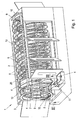
- FIG. 1 a perspective view of the cleaning device according to the invention
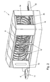
- Fig. 2 another perspective view
- Fig. 3 a sectional view according to the arrows II - II of Fig. 1
- the Fig. 4-10 Axial sections of modified formations of the transport helix
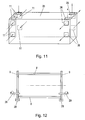
- Fig. 11 a schematic representation of the cleaning chamber
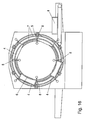
- the Fig. 12-15 schematic representations of the storage of the drivers
- the Figure 16 a cross section through the cleaning device according to the invention.
- a cleaning device 1 is shown, which is used for cleaning containers, such as beverage bottle crates, boxes or the like., Is used.
- the containers for which the device according to the invention is suitable are in particular cubic or cuboid containers which are used for the storage and / or transport of products.
- the cleaning device 1 has a transport path consisting of helical guide elements 2 in a housing 3 surrounding a cleaning chamber 25 in which the containers 4 to be cleaned are guided.
- the guide elements 2 can hereby be distinguished into radially outer guide elements 5 and radially inner guide elements 6 as well as laterally arranged, likewise helical guide elements 7. Between the radially outer guide elements 5 and the radially inner guide elements 6 extend the rod-like drivers 8 of the feed device of the cleaning device 1, which are connected to e.g. annular support elements 9 are attached.
- the support elements 9 are circumferentially or rotationally driven about the axis or helical axis, wherein the drive can be done for example via a tooth, chain or belt drive, not shown, which engages in the toothing 10 of the support members 9.
- the support elements 9 are mounted on at least two, preferably three points, not shown, which are formed for example by support rollers and / or gears, depending on the design inside and / or outside carry the support element, while at least one gear engages in the toothing 10 of the support elements 9.
- the containers to be cleaned 4 are guided at the feed point 11 in the region of the helical transport path, where it is detected by the drivers 8 and through the be moved helical transport route.
- the feed in the axial direction is effected by an interaction of the driver 8 and the lateral guide elements 7, so that the containers to be cleaned run through the cleaning device 1 helically along the axis or helical axis of the cleaning device.
- spray nozzles are arranged in different axial areas, wherein the spray nozzles 12 deliver, for example, cold water in a first axial area and spray nozzles 13 are arranged in a further axial area of the cleaning device, for example, warm water and / or water added with cleaning agents spray on the containers to be cleaned.
- pure water-carrying spray nozzles can be arranged so that the washing medium is in turn removed from the containers.
- the distance between the drivers 8 is chosen to be greater than the length of the containers 4, so that each time it passes through the vertex and the lowest point in the transport path to a slipping and abrupt stopping or to a jerky acceleration of the containers 4, whereby a additional cleaning effect is achieved.
- a nozzle 14 is arranged, for example, for drying air, with which water adhering to the containers to be cleaned can be removed.
- the containers 4 to be cleaned are conveyed by the drivers 8 to a device 15 for the removal of the cleaned containers.
- doors or inspection cover 16 can be seen, which provide a very good access to the interior of the cleaning device 1, whereby a corresponding maintenance of the cleaning device 1 is made possible.
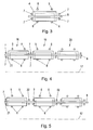
- Fig. 4 shows a modified embodiment of the transport helix in axial section, wherein the axis of the transport helix is denoted by 17.
- the lateral guide elements 7 are always arranged in pairs.
- adjacent turns 18, 19 and 20 of the transport helix can be seen, with a total of only a pair of lateral helical guide elements 7 is provided. It can be seen from the example of the container 21 that the winding 18 corresponding portion of the lateral guide elements 7 which supports one side of the container 21 and the winding 19 corresponding portion of the lateral guide elements 7, the other side of the container 21 is supported.
- two pairs of lateral guide elements are provided, namely a pair of guide elements 7 for guiding the container 21 on one side and another pair of guide elements 22 for guiding the container 21 on the other side.
- Fig. 6 In the modified training according to Fig. 6 is limited by the helical guide elements 5, 6 and 7 rectangular receiving cross section 23 of the transport spiral to the axis 17 inclined. This can lead to a better emptying of the cleaning medium from the containers.
- Fig. 7 a further modified embodiment is shown, in which the rectangular receiving cross-section 23 in the other direction is inclined, ie the open side of the containers pointing against the transport direction 24 of the transport spiral.
- the inclination of the receiving cross-section may be different in the context of the invention and depends in particular on the particular application and on the nature of the containers to be cleaned.
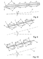
- Fig. 8-10 show modified embodiments in which the axis 17 of the transport spiral to the horizontal is inclined.
- the axis 17 can be tilted to different degrees, in particular, the inclination angle ⁇ is preferably between 5 ° and 45 °.
- the rectangular receiving cross-section 23 of the transport helix can be parallel to the axis 17 ( Fig. 8 ) or inclined ( FIGS. 9 and 10 ) can be arranged.
- the inclination of the rectangular receiving cross-section 23 to the axis 17 is the same as the inclination of the axis 17 to the horizontal, so that the rectangular receiving cross-section 23 is arranged parallel to the horizontal.
- Fig. 16 the outer 5, inner 6 and lateral guide elements 7 are particularly easy to recognize, between which the containers 4 are guided during the passage of the helical transport path.
- the feed takes place with the aid of the driver elements 8, wherein the distance between the driver elements 8 is greater than the length of the containers 4 is selected. This leads to a slipping of the containers 4 when exceeding the top dead center and to an abrupt stopping at each next driver element 8, whereby an additional cleaning effect is achieved.
Landscapes
- Engineering & Computer Science (AREA)
- Mechanical Engineering (AREA)
- Cleaning In General (AREA)
- Feeding Of Articles To Conveyors (AREA)
Priority Applications (1)
| Application Number | Priority Date | Filing Date | Title |
|---|---|---|---|
| EP13003417.6A EP2647443B1 (fr) | 2010-06-16 | 2011-06-16 | Dispositif de nettoyage de récipients |
Applications Claiming Priority (1)
| Application Number | Priority Date | Filing Date | Title |
|---|---|---|---|
| AT9922010A AT510080A1 (de) | 2010-06-16 | 2010-06-16 | Vorrichtung zum reinigen von behältnissen |
Related Child Applications (1)
| Application Number | Title | Priority Date | Filing Date |
|---|---|---|---|
| EP13003417.6A Division EP2647443B1 (fr) | 2010-06-16 | 2011-06-16 | Dispositif de nettoyage de récipients |
Publications (2)
| Publication Number | Publication Date |
|---|---|
| EP2397237A2 true EP2397237A2 (fr) | 2011-12-21 |
| EP2397237A3 EP2397237A3 (fr) | 2013-01-16 |
Family
ID=44514029
Family Applications (2)
| Application Number | Title | Priority Date | Filing Date |
|---|---|---|---|
| EP11450077A Withdrawn EP2397237A3 (fr) | 2010-06-16 | 2011-06-16 | Dispositif de nettoyage de récipients |
| EP13003417.6A Not-in-force EP2647443B1 (fr) | 2010-06-16 | 2011-06-16 | Dispositif de nettoyage de récipients |
Family Applications After (1)
| Application Number | Title | Priority Date | Filing Date |
|---|---|---|---|
| EP13003417.6A Not-in-force EP2647443B1 (fr) | 2010-06-16 | 2011-06-16 | Dispositif de nettoyage de récipients |
Country Status (2)
| Country | Link |
|---|---|
| EP (2) | EP2397237A3 (fr) |
| AT (1) | AT510080A1 (fr) |
Cited By (2)
| Publication number | Priority date | Publication date | Assignee | Title |
|---|---|---|---|---|
| EP2902121A1 (fr) * | 2014-01-30 | 2015-08-05 | Massimo Zanotti | Dispositif de lavage de conteneurs pour le transport de volailles vivantes |
| EP3984659A1 (fr) * | 2020-10-16 | 2022-04-20 | PB Entwicklungs- und Vertriebs GmbH | Dispositif de nettoyage |
Citations (2)
| Publication number | Priority date | Publication date | Assignee | Title |
|---|---|---|---|---|
| DE3315413A1 (de) | 1983-04-28 | 1984-10-31 | Robert 5470 Andernach Mürtz | Vorrichtung zum reinigen von behaeltern |
| DE10116854B4 (de) | 2001-04-04 | 2005-07-07 | Ulrich Klotzki | Waschanlage zum Reinigen von Behältnissen für den Transport und/oder die Aufbewahrung z. B. von Flaschen wie Getränkeflaschen |
Family Cites Families (7)
| Publication number | Priority date | Publication date | Assignee | Title |
|---|---|---|---|---|
| US3032798A (en) * | 1960-02-09 | 1962-05-08 | Lodge & Shipley Co | Case cleaning machine |
| US4104080A (en) * | 1976-03-11 | 1978-08-01 | Sadwith Howard M | Apparatus and method for washing and drying reusable containers |
| SU659211A1 (ru) * | 1976-03-12 | 1979-04-30 | Государственный Всесоюзный Ордена Трудового Красного Знамени Научно-Исследовательский Технологический Институт Ремонта И Эксплуатации Машинно-Тракторного Парка | Моечна машина дл очистки деталей |
| FR2467173B1 (fr) * | 1979-10-10 | 1986-12-19 | Binner Joseph | Machine automatique pour la mise en bouteilles de liquides |
| AT383056B (de) * | 1982-12-22 | 1987-05-11 | Salm O & Co Gmbh | Vorrichtung zum reinigen von wannenfoermigen behaeltern |
| DE9306403U1 (de) * | 1993-04-28 | 1993-08-12 | Wiegleb, Ludwig, 59427 Unna | Rotations-Kastenwascher |
| DE102004022745A1 (de) * | 2004-05-07 | 2005-11-24 | Groninger & Co Gmbh | Verfahren zum Reinigen von insbesondere pharmazeutischen Behältnissen |
-
2010
- 2010-06-16 AT AT9922010A patent/AT510080A1/de not_active Application Discontinuation
-
2011
- 2011-06-16 EP EP11450077A patent/EP2397237A3/fr not_active Withdrawn
- 2011-06-16 EP EP13003417.6A patent/EP2647443B1/fr not_active Not-in-force
Patent Citations (2)
| Publication number | Priority date | Publication date | Assignee | Title |
|---|---|---|---|---|
| DE3315413A1 (de) | 1983-04-28 | 1984-10-31 | Robert 5470 Andernach Mürtz | Vorrichtung zum reinigen von behaeltern |
| DE10116854B4 (de) | 2001-04-04 | 2005-07-07 | Ulrich Klotzki | Waschanlage zum Reinigen von Behältnissen für den Transport und/oder die Aufbewahrung z. B. von Flaschen wie Getränkeflaschen |
Cited By (6)
| Publication number | Priority date | Publication date | Assignee | Title |
|---|---|---|---|---|
| EP2902121A1 (fr) * | 2014-01-30 | 2015-08-05 | Massimo Zanotti | Dispositif de lavage de conteneurs pour le transport de volailles vivantes |
| WO2015114511A1 (fr) * | 2014-01-30 | 2015-08-06 | Massimo Zanotti | Dispositif de lavage de récipients pour le transport de volailles vivantes |
| US10610908B2 (en) | 2014-01-30 | 2020-04-07 | Massimo Zanotti | Device for washing containers for transporting live poultry |
| EP3984659A1 (fr) * | 2020-10-16 | 2022-04-20 | PB Entwicklungs- und Vertriebs GmbH | Dispositif de nettoyage |
| AT524319B1 (de) * | 2020-10-16 | 2022-05-15 | Pb Entw Und Vertriebs Gmbh | Reinigungsvorrichtung |
| AT524319A4 (de) * | 2020-10-16 | 2022-05-15 | Pb Entw Und Vertriebs Gmbh | Reinigungsvorrichtung |
Also Published As
| Publication number | Publication date |
|---|---|
| EP2647443B1 (fr) | 2014-11-12 |
| EP2397237A3 (fr) | 2013-01-16 |
| AT510080A1 (de) | 2012-01-15 |
| EP2647443A1 (fr) | 2013-10-09 |
Similar Documents
| Publication | Publication Date | Title |
|---|---|---|
| EP2279803B1 (fr) | Transporteur hélicoïdal | |
| DE102009053350B4 (de) | Füllelement | |
| EP3105157B1 (fr) | Système de traitement par immersion comportant un moyen pour faire tourner les objets à traiter | |
| WO2012052421A1 (fr) | Dispositif et procédé d'échantillonnage | |
| EP2030942A1 (fr) | Dispositif de répartition d'un milieu sur des récipients | |
| DE10238633B3 (de) | Sterilisiervorrichtung für Kappen von Getränkebehältern | |
| EP2695721B1 (fr) | Dispositif d'étanchéité avec possibilité de compensation pour plusieurs directions de mouvement | |
| EP2647443B1 (fr) | Dispositif de nettoyage de récipients | |
| WO2016050825A1 (fr) | Dispositif de manipulation de récipients | |
| EP3350107A1 (fr) | Transporteur de contenants | |
| DE102010051283B4 (de) | Wendelförderer | |
| EP1544154B1 (fr) | Dispositif de stérilisations pour bouchons de bouteille | |
| DE102021102822A1 (de) | Vorrichtung und Verfahren zum Transport von Behältern | |
| EP2700613B2 (fr) | Installation d'embouteillage comprenant un dispositif de réglage et procédé de nettoyage d'une installation embouteillage | |
| EP1952900A1 (fr) | Dispositif de nettoyage de récipients | |
| DE3713524C2 (de) | Vorrichtung zur Zwischenspeicherung von Gegenständen | |
| DE102008049296A1 (de) | Vorrichtung zum Abblasen oder Trocknen von Kästen oder dergleichen Behältern | |
| DE3333115C2 (fr) | ||
| DE2119267A1 (de) | Kistenwaschmaschine | |
| DE202024105553U1 (de) | Vorrichtung zum Höhentransportieren von Behältern von einem ersten Maschinenabschnitt zu einem zweiten Maschinenabschnitt | |
| DE202013101987U1 (de) | Wendelförderer | |
| EP3189889A1 (fr) | Mélangeur et outil mélangeur | |
| DE20319674U1 (de) | Schwenkbarer Dragierkessel und Lagereinrichtung für Dragierkessel | |
| AT515380B1 (de) | Verfahren zur Sanierung eines Schneckenförderers und Schneckenförderer | |
| DE102008034232A1 (de) | Verfahren und Vorrichtung zum Wenden eines Behältnisses |
Legal Events
| Date | Code | Title | Description |
|---|---|---|---|
| AK | Designated contracting states |
Kind code of ref document: A2 Designated state(s): AL AT BE BG CH CY CZ DE DK EE ES FI FR GB GR HR HU IE IS IT LI LT LU LV MC MK MT NL NO PL PT RO RS SE SI SK SM TR |
|
| AX | Request for extension of the european patent |
Extension state: BA ME |
|
| PUAI | Public reference made under article 153(3) epc to a published international application that has entered the european phase |
Free format text: ORIGINAL CODE: 0009012 |
|
| PUAL | Search report despatched |
Free format text: ORIGINAL CODE: 0009013 |
|
| AK | Designated contracting states |
Kind code of ref document: A3 Designated state(s): AL AT BE BG CH CY CZ DE DK EE ES FI FR GB GR HR HU IE IS IT LI LT LU LV MC MK MT NL NO PL PT RO RS SE SI SK SM TR |
|
| AX | Request for extension of the european patent |
Extension state: BA ME |
|
| RIC1 | Information provided on ipc code assigned before grant |
Ipc: B65G 33/04 20060101ALI20121210BHEP Ipc: B08B 9/08 20060101AFI20121210BHEP |
|
| RIN1 | Information on inventor provided before grant (corrected) |
Inventor name: VOELKER ROLAND Inventor name: PEBOECK, HELMUT |
|
| RIN1 | Information on inventor provided before grant (corrected) |
Inventor name: VOELKER ROLAND Inventor name: PEBOECK, HELMUT |
|
| RIN1 | Information on inventor provided before grant (corrected) |
Inventor name: PEBOECK, HELMUT Inventor name: VOELKER ROLAND |
|
| 17P | Request for examination filed |
Effective date: 20130624 |
|
| RBV | Designated contracting states (corrected) |
Designated state(s): AL AT BE BG CH CY CZ DE DK EE ES FI FR GB GR HR HU IE IS IT LI LT LU LV MC MK MT NL NO PL PT RO RS SE SI SK SM TR |
|
| 17Q | First examination report despatched |
Effective date: 20180822 |
|
| STAA | Information on the status of an ep patent application or granted ep patent |
Free format text: STATUS: THE APPLICATION IS DEEMED TO BE WITHDRAWN |
|
| 18D | Application deemed to be withdrawn |
Effective date: 20190103 |