EP2397247B1 - Vorrichtung und Verfahren zum Einstellen einer Spannzange einer Werkzeugmaschine - Google Patents
Vorrichtung und Verfahren zum Einstellen einer Spannzange einer Werkzeugmaschine Download PDFInfo
- Publication number
- EP2397247B1 EP2397247B1 EP10166525.5A EP10166525A EP2397247B1 EP 2397247 B1 EP2397247 B1 EP 2397247B1 EP 10166525 A EP10166525 A EP 10166525A EP 2397247 B1 EP2397247 B1 EP 2397247B1
- Authority
- EP
- European Patent Office
- Prior art keywords
- collet
- machined
- spindle
- clamp
- rotation
- Prior art date
- Legal status (The legal status is an assumption and is not a legal conclusion. Google has not performed a legal analysis and makes no representation as to the accuracy of the status listed.)
- Active
Links
Images


Classifications
-
- B—PERFORMING OPERATIONS; TRANSPORTING
- B23—MACHINE TOOLS; METAL-WORKING NOT OTHERWISE PROVIDED FOR
- B23B—TURNING; BORING
- B23B31/00—Chucks; Expansion mandrels; Adaptations thereof for remote control
- B23B31/02—Chucks
- B23B31/10—Chucks characterised by the retaining or gripping devices or their immediate operating means
- B23B31/12—Chucks with simultaneously-acting jaws, whether or not also individually adjustable
- B23B31/20—Longitudinally-split sleeves, e.g. collet chucks
- B23B31/201—Characterized by features relating primarily to remote control of the gripping means
- B23B31/207—Characterized by features relating primarily to remote control of the gripping means using mechanical transmission through the spindle
- B23B31/2073—Axially fixed cam, moving jaws
-
- B—PERFORMING OPERATIONS; TRANSPORTING
- B23—MACHINE TOOLS; METAL-WORKING NOT OTHERWISE PROVIDED FOR
- B23B—TURNING; BORING
- B23B2231/00—Details of chucks, toolholder shanks or tool shanks
- B23B2231/20—Collet chucks
- B23B2231/2005—Keys preventing rotation
-
- B—PERFORMING OPERATIONS; TRANSPORTING
- B23—MACHINE TOOLS; METAL-WORKING NOT OTHERWISE PROVIDED FOR
- B23B—TURNING; BORING
- B23B2260/00—Details of constructional elements
- B23B2260/004—Adjustable elements
-
- B—PERFORMING OPERATIONS; TRANSPORTING
- B23—MACHINE TOOLS; METAL-WORKING NOT OTHERWISE PROVIDED FOR
- B23B—TURNING; BORING
- B23B2270/00—Details of turning, boring or drilling machines, processes or tools not otherwise provided for
- B23B2270/60—Prevention of rotation
Definitions
- the invention relates to a device for adjusting a gripper for a machine tool according to the preamble of claim 1.
- the invention also relates to a spindle comprising said adjusting device and to a method of adjusting a such device.
- Known machine tools such as lathe machines, which include multiple pins for receiving the material to be machined. This is usually in the form of bar or slugs.
- the pins are generally arranged to rotate with the material to be machined about an axis.
- the front end (the side where the material to be machined) of the spindle comprises means, such as a clamp, for retaining the workpiece. The function of this clamp is to clamp the material to be machined and thus prevent the workpiece from moving during machining.
- the material to be machined is guided axially through the spindle by a clamping tube.
- the clamp may be an integral part of this tube or the clamp and the tube may be two different parts but assembled to form a unitary entity.
- the pin also includes a fixed prisoner whose function is to guide the clamp and prevent it from turning in its housing.
- Patent US 2,821,404 discloses an example of a solution for a collet chuck. This solution includes a pin that can be inserted in a slot in the clamp to block it. The adjustment of the clamp is done from the back of the clamp.
- the object of the present invention is to overcome the problems of known solutions.
- the present invention therefore proposes a solution for adjusting the pinch of a spindle for a machine tool as explained in more detail below.
- the subject of the invention is a device for adjusting a clamp according to claim 1.
- the proposed device allows all the manipulations from the front of the machine while the current solutions require to do it from the rear. These manipulations include locking / unlocking the clamp, adjusting the clamp and changing the clamp.
- the clamp can be assembled with a clamping tube to form a fixed part. In this case, the clamp is changed together with the clamping tube.
- the present solution therefore guarantees increased accessibility, reduced intervention time and reduced costs.
- the invention also relates to a spindle for a machine tool comprising said adjustment device or said assembly.
- the invention also relates to a method of adjusting a clamp for a machine tool according to claim 13.
- the other aspects of the present invention are in the dependent claims.
- the figure 1 is a sectional and perspective view of a pin 101 comprising the adjusting device 301 (shown in more detail on FIG. figure 3 ) according to an embodiment of the present invention.
- the inner parts of the pin 101 are protected by a pin body 103 and a protective flange 105 on the advancing side of the material to be machined (which is therefore in this figure the right side).
- clamping tube 107 which axially passes through the pin 101.
- This clamping tube 107 is arranged to receive the material (not shown in the figures) to be machined such as a metal bar.
- a clip 109 On the forward side of the bar is a clip 109 which can be changed and / or adjusted as explained later to receive bars with different diameters.
- the clamp 109 is thus arranged to tighten the bar firmly in place during the machining of the bar.
- the clamp 109 and the clamping tube 107 are two different parts assembled by screwing and glued. This principle is chosen for reasons of manufacturing costs.
- An anti-rotation means of the clamp 111 hereinafter called a prisoner 111, is also illustrated on the figure 1 .
- This prisoner 111 is controlled by a control means of the anti-rotation means of the clamp 113, hereinafter called a control axis of the prisoner 113.
- a locking means of the control axis of the prisoner 115 is used to locking / unlocking the prisoner's control shaft 113.
- the rear portion 117 of the spindle comprises inter alia a clamping system for pulling the clamping tube 107 after the adjustment of the clamp 109 has been made from the front. On the figure 1 , the tightening by the clamping system is performed by pulling the clamping tube 107 and consequently the clamp 109 to the left on the figure 1 .
- the present invention is based on the principle that depending on the diameters of bars to be machined, the clamp 109 and possibly the clamping tube 107 must be adapted.
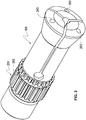
- the figure 2 illustrates in more detail the clip 109 and the figure 3 shows the clamp 109 with the adjusting device 301 of the clamp 109.
- the adjusting device 301 comprises the following elements: the prisoner 111, the control shaft 113 and the locking means of the control pin 115.
- the clamp 109 also comprises a toothed portion 201 around the clamp 109 to receive the prisoner 111 and a groove 202 for sliding therein a seal O-ring type 400 (shown in FIG. figure 4 ). This groove 202 or groove is therefore intended for receive a seal 400 for sealing the rear part of the spindle. This, in order to reduce the frequency of cleaning the clamping tubes 107.
- the prisoner 111 is fixed. Its function is to guide the clamp 109 and prevent it from rotating in its housing.
- the prisoner 111 is movable, actuated by the control pin 113, which allows it to be released from the toothing 201 and to turn the clip 109 together with the clamping tube 107.
- the rotation of the clip 109 is performed with tooling not shown which is taken in the front holes 203 of the clamp 109.
- the rotation of the clamp 109 moves the clamp 109 axially. Depending on the direction of rotation applied, the clamp 109 will enter or leave its housing, which increases or decreases the clamping force.
- the prisoner 111 is therefore removable and controlled from the front.
- the control shaft 113 is controlled from the front by turning it mechanically using a tool which is taken in the hole 205 of the control shaft 113.
- the end of the control shaft 113 which is in contact with the Prisoner 111 comprises a pin 401 whose position is slightly eccentric at the cross-sectional level of the control shaft 113.
- the control pin 113 could be different, for example a spring, operable by a hydraulic pressure, etc.
- the prisoner 111 itself may be a device for releasing and / or locking the clamp 109 in rotation, once the adjustment is made.
- the configuration illustrated on the figure 2 allows the clamp 109 to always move axially, for opening or closing, when the prisoner 111 is in place.
Landscapes
- Engineering & Computer Science (AREA)
- Mechanical Engineering (AREA)
- Gripping On Spindles (AREA)
- Jigs For Machine Tools (AREA)
- Machine Tool Sensing Apparatuses (AREA)
Claims (13)
- Eine Vorrichtung zur Einstellung (301) einer Spannzange (109) für eine Spindel (101) einer Werkzeugmaschine, wobei die Vorrichtung (301) umfasst:• Eine Spannzange (109) zum Halten des zu bearbeitenden Materials;• Ein Mittel zur Drehblockierung (111) der Spannzange (109), welches angeordnet ist, um mit der Spannzange (109) in Eingriff gebracht zu werden, um diese in Rotation zu blockieren oder von der Spannzange (109) zurückgezogen zu werden, um dieser Drehen zu gestatten; und• Ein Steuermittel (113) für das Drehblockierungsmittel (111) der Spannzange (109),dadurch gekennzeichnet, dass die Spannzange (109) einen Zahnabschnitt (201) rund um die Spannzange (109) zur Aufnahme des Drehblockierungsmittels (111) der Spannzange (109) aufweist, und die Spannzange (109) ausgebildet ist, um ihre Einstellung von der Seite der Spannzange (109) zu ermöglichen, an welcher sich der zu bearbeitende Materialabschnitt befindet.
- Die Vorrichtung (301) nach einem der vorhergehenden Ansprüche, wobei das Steuermittel (113) an einer seiner Enden mit dem Drehblockierungsmittel (111) der Spannzange (109) verbunden ist, um das Drehblockierungsmittel (111) der Spannzange (109) zu blockieren/deblockieren und wobei das Steuermittel (113) ausgebildet ist, um von der Seite gesteuert zu werden, an welcher sich das zu bearbeitende Material befindet.
- Die Vorrichtung (301) nach Anspruch 2, wobei das Steuermittel (113) eine Feder oder eine Steuerspindel, welche ausgebildet ist, um pneumatisch oder hydraulisch gesteuert zu werden, oder um durch mechanisches Drehen dieser Steuerspindel gesteuert zu werden.
- Die Vorrichtung (301) nach einem der vorhergehenden Ansprüche, bei welcher die Vorrichtung (301) weiter ein Mittel zum Blockieren/Deblockieren des Steuermittels (113) der Spannzange (109) umfasst.
- Die Vorrichtung (301) nach einem der vorhergehenden Ansprüche, bei welcher in dem entsperrten Zustand, die Spannzange (109) ausgebildet ist, um zu rotieren und auf diese Weise ihre Aufnahme zu verlassen, so dass sich die Klemmkräfte reduzieren, und in dem blockierten Zustand die Spannzange (109) drehblockiert ist.
- Die Vorrichtung nach Anspruch 5, wobei die Spannzange (109) ausgebildet ist, um sich axial in der Spindel (101) zwischen einer deblockierten Position und einer blockierten Position zu bewegen, um gespannt/entspannt zu werden.
- Die Vorrichtung nach einem der Ansprüche 5 bis 6, bei welcher die Spannzange (109) eine Ausnehmung (202) an dem Aussenumfang aufweist, um einen Dichtring (400) aufzunehmen.
- Die Vorrichtung nach einem der Ansprüche 5 bis 7, bei welcher in dem entsperrten Zustand die Spannzange (109) ausgebildet ist, um von einem Werkzeug von der Seite gedreht zu werden, an welcher sich der zu bearbeitende Materialabschnitt befindet, um die Spannzange (109) axial in der Spindel (101) zu bewegen und so die Klemmkraft einzustellen.
- Die Vorrichtung nach einem der Ansprüche 5 bis 8, bei welcher die Vorrichtung (301) weiter ein Klemmrohr (107) umfasst, wobei die Spannzange (109) ausgebildet ist, um mit dem Klemmrohr (107) in dem entsperrten Zustand zu drehen.
- Eine Spindel (101), umfassend die Vorrichtung (301) nach einem der vorhergehenden Ansprüche.
- Die Spindel (101) nach Anspruch 10, bei welcher die Spindel (101) weiter ein Klemmsystem umfasst, um die Spannzange (109) axial in der Spindel (101) nach der Einstellung der Spannzange (109) von der Seite zu bewegen, an welcher sich der zu bearbeitende Materialabschnitt befindet.
- Die Spindel (101) nach einem der Ansprüche 10 bis 11, bei welcher sich das Klemmsystem an der gegenüberliegenden Seite in Bezug zu der Seite befindet, an welcher sich der zu bearbeitende Materialabschnitt befindet.
- Ein Verfahren zur Einstellung einer Spannzange (109) für eine Werkzeugmaschine, umfassend ein Klemmsystem der Spannzange (109), welches an der gegenüberliegenden Seite in Bezug zu der Seite angeordnet ist, an welcher sich der zu bearbeitende Materialabschnitt befindet, wobei das Verfahren umfasst:• das Einführen eines zu bearbeitenden Stücks in die Spannzange (109), welche ausgebildet ist, um das zu bearbeitende Material zu halten, und welche einen Zahnabschnitt um diese (109) umfasst, um ein Mittel zur Drehblockierung (111) der Spannzange (109) aufzunehmen;• das Einstellen der Spannzange derart, dass sich das zu bearbeitende Stück mit Schwierigkeiten in der Spannzange (109) axial bewegt und wobei nach der Einstellung das Drehblockierungsmittel (111) in Eingriff mit der Spannzange (109) steht, um letztere in Rotation zu blockieren; und• das Festklemmen der Spannzange (109) durch das Klemmsystem,bei welchem das Einstellen der Spannzange von der Seite der Spannzange ausgeführt wird, an welcher sich der zu bearbeitende Materialabschnitt befindet.
Priority Applications (2)
| Application Number | Priority Date | Filing Date | Title |
|---|---|---|---|
| ES10166525.5T ES2648898T3 (es) | 2010-06-18 | 2010-06-18 | Dispositivo y procedimiento de ajuste de una pinza para una máquina-herramienta |
| EP10166525.5A EP2397247B1 (de) | 2010-06-18 | 2010-06-18 | Vorrichtung und Verfahren zum Einstellen einer Spannzange einer Werkzeugmaschine |
Applications Claiming Priority (1)
| Application Number | Priority Date | Filing Date | Title |
|---|---|---|---|
| EP10166525.5A EP2397247B1 (de) | 2010-06-18 | 2010-06-18 | Vorrichtung und Verfahren zum Einstellen einer Spannzange einer Werkzeugmaschine |
Publications (2)
| Publication Number | Publication Date |
|---|---|
| EP2397247A1 EP2397247A1 (de) | 2011-12-21 |
| EP2397247B1 true EP2397247B1 (de) | 2017-10-04 |
Family
ID=43063309
Family Applications (1)
| Application Number | Title | Priority Date | Filing Date |
|---|---|---|---|
| EP10166525.5A Active EP2397247B1 (de) | 2010-06-18 | 2010-06-18 | Vorrichtung und Verfahren zum Einstellen einer Spannzange einer Werkzeugmaschine |
Country Status (2)
| Country | Link |
|---|---|
| EP (1) | EP2397247B1 (de) |
| ES (1) | ES2648898T3 (de) |
Families Citing this family (2)
| Publication number | Priority date | Publication date | Assignee | Title |
|---|---|---|---|---|
| GB2577305A (en) * | 2018-09-21 | 2020-03-25 | Edward Houghton Larry | A workpiece holding apparatus |
| CN116673913B (zh) * | 2023-05-05 | 2024-01-09 | 天津市拓达车辆配件有限公司 | 一种电机加工装夹用辅助减震装置 |
Family Cites Families (9)
| Publication number | Priority date | Publication date | Assignee | Title |
|---|---|---|---|---|
| US2821404A (en) * | 1953-10-21 | 1958-01-28 | Cushman Chuck Co | Collet chuck with internal work stop provisions |
| US3583714A (en) * | 1968-11-27 | 1971-06-08 | Gleason Works | Chuck and collet for shank pinions and the like |
| FR2097214A5 (de) * | 1970-05-25 | 1972-03-03 | Dutrey Rene | |
| DE8913330U1 (de) * | 1989-11-11 | 1990-03-22 | Schmidt, Claus, 7120 Bietigheim-Bissingen | Spannfutter |
| DE4025944A1 (de) * | 1990-08-16 | 1992-02-20 | Hainbuch Praez Spannwerkzeug | Einstellbare spannzange |
| GB2279277B (en) * | 1993-06-28 | 1997-03-05 | Crawford Collets Ltd | Collets |
| US5806859A (en) * | 1996-06-24 | 1998-09-15 | Saccomanno, Iii; Matthew | Self-contained collet adaptor |
| US6036415A (en) * | 1998-09-04 | 2000-03-14 | Hardinge, Inc. | Spindle for gripping and closing a mounting member |
| US6257595B1 (en) * | 1998-09-04 | 2001-07-10 | Hardinge Inc. | Collect chuck with quick-change cap |
-
2010
- 2010-06-18 EP EP10166525.5A patent/EP2397247B1/de active Active
- 2010-06-18 ES ES10166525.5T patent/ES2648898T3/es active Active
Non-Patent Citations (1)
| Title |
|---|
| None * |
Also Published As
| Publication number | Publication date |
|---|---|
| ES2648898T3 (es) | 2018-01-08 |
| EP2397247A1 (de) | 2011-12-21 |
Similar Documents
| Publication | Publication Date | Title |
|---|---|---|
| FR2491807A1 (fr) | Dispositif de prise de pieces realisant successivement un serrage et un blocage | |
| FR2611554A1 (fr) | Appareil de serrage d'un outil en particulier dans une broche de machine-outil | |
| FR2565865A1 (fr) | Mandrin de serrage de pieces, et mors rapporte, ensemble de mors et dispositif de fixation de mors pour ce mandrin | |
| EP2397247B1 (de) | Vorrichtung und Verfahren zum Einstellen einer Spannzange einer Werkzeugmaschine | |
| EP1317329B1 (de) | Bohrkopf | |
| FR2468428A1 (fr) | Dispositif de fixation d'outil, notamment pour perceuse a main | |
| FR2612438A1 (fr) | Machine-outil, notamment perceuse ou taraudeuse | |
| FR3132450A1 (fr) | Accessoire d’interface de travail, kit de travail et procédé de soudage par friction-malaxage | |
| EP1796871A1 (de) | Vorrichtung zum einspannen eines werkzeugeinsatzes in eine schleifmaschine | |
| EP0903194A1 (de) | Spannvorrichtung | |
| FR2584959A1 (fr) | Outil de tournage | |
| FR2961730A3 (fr) | Mandrin a serrage combine auto-serrant et a cle. | |
| FR2709260A1 (fr) | Perceuse à main notamment perforateur. | |
| FR2896713A1 (fr) | Mandrin porte-outil pour l'equipement d'une machine tournante | |
| FR2566690A1 (fr) | Taraudeuse | |
| EP1702694B1 (de) | Werkzeugspannfutter für drehende Maschine, mit Verriegelungsmittel | |
| CA2548114A1 (fr) | Dispositif de retenue d'une clavette d'outil pour appareil de demolition a percussion | |
| FR2972664A1 (fr) | Broche a serrage rapide | |
| EP1680258A2 (de) | Dem werkzeug einer schneidwerkzeugmaschine zugeordnete saugvorrichtung | |
| EP0537406B1 (de) | Stangenführungsautomat für Drehautomat | |
| EP2106306B1 (de) | Vorrichtung zum biegen eines metallrohrs durch wickeln auf eine formrolle | |
| EP1726389B1 (de) | Werkzeugmaschine mit mobiler Führungsbuchse für die Herstellung von Teilen durch Abstechen | |
| EP4183505A1 (de) | Spannzange für werkzeugmaschinen | |
| EP0114443B1 (de) | Werkzeug-Support für Werkzeugmaschine | |
| CH623762A5 (de) |
Legal Events
| Date | Code | Title | Description |
|---|---|---|---|
| AK | Designated contracting states |
Kind code of ref document: A1 Designated state(s): AL AT BE BG CH CY CZ DE DK EE ES FI FR GB GR HR HU IE IS IT LI LT LU LV MC MK MT NL NO PL PT RO SE SI SK SM TR |
|
| AX | Request for extension of the european patent |
Extension state: BA ME RS |
|
| PUAI | Public reference made under article 153(3) epc to a published international application that has entered the european phase |
Free format text: ORIGINAL CODE: 0009012 |
|
| 17P | Request for examination filed |
Effective date: 20120615 |
|
| GRAP | Despatch of communication of intention to grant a patent |
Free format text: ORIGINAL CODE: EPIDOSNIGR1 |
|
| INTG | Intention to grant announced |
Effective date: 20170630 |
|
| GRAS | Grant fee paid |
Free format text: ORIGINAL CODE: EPIDOSNIGR3 |
|
| GRAJ | Information related to disapproval of communication of intention to grant by the applicant or resumption of examination proceedings by the epo deleted |
Free format text: ORIGINAL CODE: EPIDOSDIGR1 |
|
| GRAL | Information related to payment of fee for publishing/printing deleted |
Free format text: ORIGINAL CODE: EPIDOSDIGR3 |
|
| GRAA | (expected) grant |
Free format text: ORIGINAL CODE: 0009210 |
|
| GRAR | Information related to intention to grant a patent recorded |
Free format text: ORIGINAL CODE: EPIDOSNIGR71 |
|
| INTC | Intention to grant announced (deleted) | ||
| AK | Designated contracting states |
Kind code of ref document: B1 Designated state(s): AL AT BE BG CH CY CZ DE DK EE ES FI FR GB GR HR HU IE IS IT LI LT LU LV MC MK MT NL NO PL PT RO SE SI SK SM TR |
|
| INTG | Intention to grant announced |
Effective date: 20170830 |
|
| REG | Reference to a national code |
Ref country code: GB Ref legal event code: FG4D Free format text: NOT ENGLISH |
|
| REG | Reference to a national code |
Ref country code: CH Ref legal event code: EP Ref country code: CH Ref legal event code: NV Representative=s name: BOVARD AG PATENT- UND MARKENANWAELTE, CH |
|
| REG | Reference to a national code |
Ref country code: AT Ref legal event code: REF Ref document number: 933534 Country of ref document: AT Kind code of ref document: T Effective date: 20171015 |
|
| REG | Reference to a national code |
Ref country code: IE Ref legal event code: FG4D Free format text: LANGUAGE OF EP DOCUMENT: FRENCH |
|
| REG | Reference to a national code |
Ref country code: DE Ref legal event code: R096 Ref document number: 602010045692 Country of ref document: DE |
|
| REG | Reference to a national code |
Ref country code: ES Ref legal event code: FG2A Ref document number: 2648898 Country of ref document: ES Kind code of ref document: T3 Effective date: 20180108 |
|
| REG | Reference to a national code |
Ref country code: NL Ref legal event code: MP Effective date: 20171004 |
|
| REG | Reference to a national code |
Ref country code: LT Ref legal event code: MG4D |
|
| REG | Reference to a national code |
Ref country code: AT Ref legal event code: MK05 Ref document number: 933534 Country of ref document: AT Kind code of ref document: T Effective date: 20171004 |
|
| PG25 | Lapsed in a contracting state [announced via postgrant information from national office to epo] |
Ref country code: NL Free format text: LAPSE BECAUSE OF FAILURE TO SUBMIT A TRANSLATION OF THE DESCRIPTION OR TO PAY THE FEE WITHIN THE PRESCRIBED TIME-LIMIT Effective date: 20171004 |
|
| PG25 | Lapsed in a contracting state [announced via postgrant information from national office to epo] |
Ref country code: SE Free format text: LAPSE BECAUSE OF FAILURE TO SUBMIT A TRANSLATION OF THE DESCRIPTION OR TO PAY THE FEE WITHIN THE PRESCRIBED TIME-LIMIT Effective date: 20171004 Ref country code: LT Free format text: LAPSE BECAUSE OF FAILURE TO SUBMIT A TRANSLATION OF THE DESCRIPTION OR TO PAY THE FEE WITHIN THE PRESCRIBED TIME-LIMIT Effective date: 20171004 Ref country code: FI Free format text: LAPSE BECAUSE OF FAILURE TO SUBMIT A TRANSLATION OF THE DESCRIPTION OR TO PAY THE FEE WITHIN THE PRESCRIBED TIME-LIMIT Effective date: 20171004 Ref country code: NO Free format text: LAPSE BECAUSE OF FAILURE TO SUBMIT A TRANSLATION OF THE DESCRIPTION OR TO PAY THE FEE WITHIN THE PRESCRIBED TIME-LIMIT Effective date: 20180104 |
|
| PG25 | Lapsed in a contracting state [announced via postgrant information from national office to epo] |
Ref country code: BG Free format text: LAPSE BECAUSE OF FAILURE TO SUBMIT A TRANSLATION OF THE DESCRIPTION OR TO PAY THE FEE WITHIN THE PRESCRIBED TIME-LIMIT Effective date: 20180104 Ref country code: LV Free format text: LAPSE BECAUSE OF FAILURE TO SUBMIT A TRANSLATION OF THE DESCRIPTION OR TO PAY THE FEE WITHIN THE PRESCRIBED TIME-LIMIT Effective date: 20171004 Ref country code: HR Free format text: LAPSE BECAUSE OF FAILURE TO SUBMIT A TRANSLATION OF THE DESCRIPTION OR TO PAY THE FEE WITHIN THE PRESCRIBED TIME-LIMIT Effective date: 20171004 Ref country code: IS Free format text: LAPSE BECAUSE OF FAILURE TO SUBMIT A TRANSLATION OF THE DESCRIPTION OR TO PAY THE FEE WITHIN THE PRESCRIBED TIME-LIMIT Effective date: 20180204 Ref country code: GR Free format text: LAPSE BECAUSE OF FAILURE TO SUBMIT A TRANSLATION OF THE DESCRIPTION OR TO PAY THE FEE WITHIN THE PRESCRIBED TIME-LIMIT Effective date: 20180105 Ref country code: AT Free format text: LAPSE BECAUSE OF FAILURE TO SUBMIT A TRANSLATION OF THE DESCRIPTION OR TO PAY THE FEE WITHIN THE PRESCRIBED TIME-LIMIT Effective date: 20171004 |
|
| REG | Reference to a national code |
Ref country code: FR Ref legal event code: PLFP Year of fee payment: 9 |
|
| REG | Reference to a national code |
Ref country code: DE Ref legal event code: R097 Ref document number: 602010045692 Country of ref document: DE |
|
| PG25 | Lapsed in a contracting state [announced via postgrant information from national office to epo] |
Ref country code: DK Free format text: LAPSE BECAUSE OF FAILURE TO SUBMIT A TRANSLATION OF THE DESCRIPTION OR TO PAY THE FEE WITHIN THE PRESCRIBED TIME-LIMIT Effective date: 20171004 Ref country code: SK Free format text: LAPSE BECAUSE OF FAILURE TO SUBMIT A TRANSLATION OF THE DESCRIPTION OR TO PAY THE FEE WITHIN THE PRESCRIBED TIME-LIMIT Effective date: 20171004 Ref country code: EE Free format text: LAPSE BECAUSE OF FAILURE TO SUBMIT A TRANSLATION OF THE DESCRIPTION OR TO PAY THE FEE WITHIN THE PRESCRIBED TIME-LIMIT Effective date: 20171004 |
|
| PLBE | No opposition filed within time limit |
Free format text: ORIGINAL CODE: 0009261 |
|
| STAA | Information on the status of an ep patent application or granted ep patent |
Free format text: STATUS: NO OPPOSITION FILED WITHIN TIME LIMIT |
|
| PG25 | Lapsed in a contracting state [announced via postgrant information from national office to epo] |
Ref country code: PL Free format text: LAPSE BECAUSE OF FAILURE TO SUBMIT A TRANSLATION OF THE DESCRIPTION OR TO PAY THE FEE WITHIN THE PRESCRIBED TIME-LIMIT Effective date: 20171004 Ref country code: SM Free format text: LAPSE BECAUSE OF FAILURE TO SUBMIT A TRANSLATION OF THE DESCRIPTION OR TO PAY THE FEE WITHIN THE PRESCRIBED TIME-LIMIT Effective date: 20171004 Ref country code: RO Free format text: LAPSE BECAUSE OF FAILURE TO SUBMIT A TRANSLATION OF THE DESCRIPTION OR TO PAY THE FEE WITHIN THE PRESCRIBED TIME-LIMIT Effective date: 20171004 |
|
| 26N | No opposition filed |
Effective date: 20180705 |
|
| PG25 | Lapsed in a contracting state [announced via postgrant information from national office to epo] |
Ref country code: MT Free format text: LAPSE BECAUSE OF FAILURE TO SUBMIT A TRANSLATION OF THE DESCRIPTION OR TO PAY THE FEE WITHIN THE PRESCRIBED TIME-LIMIT Effective date: 20171004 |
|
| PG25 | Lapsed in a contracting state [announced via postgrant information from national office to epo] |
Ref country code: SI Free format text: LAPSE BECAUSE OF FAILURE TO SUBMIT A TRANSLATION OF THE DESCRIPTION OR TO PAY THE FEE WITHIN THE PRESCRIBED TIME-LIMIT Effective date: 20171004 |
|
| GBPC | Gb: european patent ceased through non-payment of renewal fee |
Effective date: 20180618 |
|
| REG | Reference to a national code |
Ref country code: BE Ref legal event code: MM Effective date: 20180630 |
|
| REG | Reference to a national code |
Ref country code: IE Ref legal event code: MM4A |
|
| PG25 | Lapsed in a contracting state [announced via postgrant information from national office to epo] |
Ref country code: MC Free format text: LAPSE BECAUSE OF FAILURE TO SUBMIT A TRANSLATION OF THE DESCRIPTION OR TO PAY THE FEE WITHIN THE PRESCRIBED TIME-LIMIT Effective date: 20171004 Ref country code: LU Free format text: LAPSE BECAUSE OF NON-PAYMENT OF DUE FEES Effective date: 20180618 |
|
| PG25 | Lapsed in a contracting state [announced via postgrant information from national office to epo] |
Ref country code: GB Free format text: LAPSE BECAUSE OF NON-PAYMENT OF DUE FEES Effective date: 20180618 Ref country code: IE Free format text: LAPSE BECAUSE OF NON-PAYMENT OF DUE FEES Effective date: 20180618 |
|
| PG25 | Lapsed in a contracting state [announced via postgrant information from national office to epo] |
Ref country code: BE Free format text: LAPSE BECAUSE OF NON-PAYMENT OF DUE FEES Effective date: 20180630 |
|
| PG25 | Lapsed in a contracting state [announced via postgrant information from national office to epo] |
Ref country code: HU Free format text: LAPSE BECAUSE OF FAILURE TO SUBMIT A TRANSLATION OF THE DESCRIPTION OR TO PAY THE FEE WITHIN THE PRESCRIBED TIME-LIMIT; INVALID AB INITIO Effective date: 20100618 Ref country code: PT Free format text: LAPSE BECAUSE OF FAILURE TO SUBMIT A TRANSLATION OF THE DESCRIPTION OR TO PAY THE FEE WITHIN THE PRESCRIBED TIME-LIMIT Effective date: 20171004 |
|
| PG25 | Lapsed in a contracting state [announced via postgrant information from national office to epo] |
Ref country code: CY Free format text: LAPSE BECAUSE OF FAILURE TO SUBMIT A TRANSLATION OF THE DESCRIPTION OR TO PAY THE FEE WITHIN THE PRESCRIBED TIME-LIMIT Effective date: 20171004 Ref country code: MK Free format text: LAPSE BECAUSE OF NON-PAYMENT OF DUE FEES Effective date: 20171004 |
|
| PG25 | Lapsed in a contracting state [announced via postgrant information from national office to epo] |
Ref country code: AL Free format text: LAPSE BECAUSE OF FAILURE TO SUBMIT A TRANSLATION OF THE DESCRIPTION OR TO PAY THE FEE WITHIN THE PRESCRIBED TIME-LIMIT Effective date: 20171004 |
|
| PGFP | Annual fee paid to national office [announced via postgrant information from national office to epo] |
Ref country code: ES Payment date: 20220829 Year of fee payment: 13 |
|
| P01 | Opt-out of the competence of the unified patent court (upc) registered |
Effective date: 20230630 |
|
| REG | Reference to a national code |
Ref country code: ES Ref legal event code: FD2A Effective date: 20240731 |
|
| PG25 | Lapsed in a contracting state [announced via postgrant information from national office to epo] |
Ref country code: ES Free format text: LAPSE BECAUSE OF NON-PAYMENT OF DUE FEES Effective date: 20230619 |
|
| PG25 | Lapsed in a contracting state [announced via postgrant information from national office to epo] |
Ref country code: ES Free format text: LAPSE BECAUSE OF NON-PAYMENT OF DUE FEES Effective date: 20230619 |
|
| PGFP | Annual fee paid to national office [announced via postgrant information from national office to epo] |
Ref country code: DE Payment date: 20250618 Year of fee payment: 16 |
|
| PGFP | Annual fee paid to national office [announced via postgrant information from national office to epo] |
Ref country code: FR Payment date: 20250624 Year of fee payment: 16 |
|
| PGFP | Annual fee paid to national office [announced via postgrant information from national office to epo] |
Ref country code: TR Payment date: 20250611 Year of fee payment: 16 |
|
| PGFP | Annual fee paid to national office [announced via postgrant information from national office to epo] |
Ref country code: CZ Payment date: 20250610 Year of fee payment: 16 |
|
| PGFP | Annual fee paid to national office [announced via postgrant information from national office to epo] |
Ref country code: IT Payment date: 20250619 Year of fee payment: 16 |
|
| PGFP | Annual fee paid to national office [announced via postgrant information from national office to epo] |
Ref country code: CH Payment date: 20250701 Year of fee payment: 16 |