EP2397441A1 - Vorrichtung zur herstellung eines ausgerichteten kohlenstoffnanoröhrchenaggregats - Google Patents
Vorrichtung zur herstellung eines ausgerichteten kohlenstoffnanoröhrchenaggregats Download PDFInfo
- Publication number
- EP2397441A1 EP2397441A1 EP10741067A EP10741067A EP2397441A1 EP 2397441 A1 EP2397441 A1 EP 2397441A1 EP 10741067 A EP10741067 A EP 10741067A EP 10741067 A EP10741067 A EP 10741067A EP 2397441 A1 EP2397441 A1 EP 2397441A1
- Authority
- EP
- European Patent Office
- Prior art keywords
- catalyst
- gas
- raw material
- furnace
- substrate
- Prior art date
- Legal status (The legal status is an assumption and is not a legal conclusion. Google has not performed a legal analysis and makes no representation as to the accuracy of the status listed.)
- Granted
Links
Images

Classifications
-
- C—CHEMISTRY; METALLURGY
- C01—INORGANIC CHEMISTRY
- C01B—NON-METALLIC ELEMENTS; COMPOUNDS THEREOF; METALLOIDS OR COMPOUNDS THEREOF NOT COVERED BY SUBCLASS C01C
- C01B32/00—Carbon; Compounds thereof
- C01B32/15—Nano-sized carbon materials
- C01B32/158—Carbon nanotubes
-
- B—PERFORMING OPERATIONS; TRANSPORTING
- B01—PHYSICAL OR CHEMICAL PROCESSES OR APPARATUS IN GENERAL
- B01J—CHEMICAL OR PHYSICAL PROCESSES, e.g. CATALYSIS OR COLLOID CHEMISTRY; THEIR RELEVANT APPARATUS
- B01J15/00—Chemical processes in general for reacting gaseous media with non-particulate solids, e.g. sheet material; Apparatus specially adapted therefor
- B01J15/005—Chemical processes in general for reacting gaseous media with non-particulate solids, e.g. sheet material; Apparatus specially adapted therefor in the presence of catalytically active bodies, e.g. porous plates
-
- B—PERFORMING OPERATIONS; TRANSPORTING
- B01—PHYSICAL OR CHEMICAL PROCESSES OR APPARATUS IN GENERAL
- B01J—CHEMICAL OR PHYSICAL PROCESSES, e.g. CATALYSIS OR COLLOID CHEMISTRY; THEIR RELEVANT APPARATUS
- B01J19/00—Chemical, physical or physico-chemical processes in general; Their relevant apparatus
- B01J19/08—Processes employing the direct application of electric or wave energy, or particle radiation; Apparatus therefor
- B01J19/087—Processes employing the direct application of electric or wave energy, or particle radiation; Apparatus therefor employing electric or magnetic energy
- B01J19/088—Processes employing the direct application of electric or wave energy, or particle radiation; Apparatus therefor employing electric or magnetic energy giving rise to electric discharges
-
- B—PERFORMING OPERATIONS; TRANSPORTING
- B01—PHYSICAL OR CHEMICAL PROCESSES OR APPARATUS IN GENERAL
- B01J—CHEMICAL OR PHYSICAL PROCESSES, e.g. CATALYSIS OR COLLOID CHEMISTRY; THEIR RELEVANT APPARATUS
- B01J19/00—Chemical, physical or physico-chemical processes in general; Their relevant apparatus
- B01J19/08—Processes employing the direct application of electric or wave energy, or particle radiation; Apparatus therefor
- B01J19/12—Processes employing the direct application of electric or wave energy, or particle radiation; Apparatus therefor employing electromagnetic waves
- B01J19/122—Incoherent waves
- B01J19/126—Microwaves
-
- B—PERFORMING OPERATIONS; TRANSPORTING
- B01—PHYSICAL OR CHEMICAL PROCESSES OR APPARATUS IN GENERAL
- B01J—CHEMICAL OR PHYSICAL PROCESSES, e.g. CATALYSIS OR COLLOID CHEMISTRY; THEIR RELEVANT APPARATUS
- B01J19/00—Chemical, physical or physico-chemical processes in general; Their relevant apparatus
- B01J19/18—Stationary reactors having moving elements inside
- B01J19/22—Stationary reactors having moving elements inside in the form of endless belts
-
- B—PERFORMING OPERATIONS; TRANSPORTING
- B82—NANOTECHNOLOGY
- B82Y—SPECIFIC USES OR APPLICATIONS OF NANOSTRUCTURES; MEASUREMENT OR ANALYSIS OF NANOSTRUCTURES; MANUFACTURE OR TREATMENT OF NANOSTRUCTURES
- B82Y30/00—Nanotechnology for materials or surface science, e.g. nanocomposites
-
- C—CHEMISTRY; METALLURGY
- C01—INORGANIC CHEMISTRY
- C01B—NON-METALLIC ELEMENTS; COMPOUNDS THEREOF; METALLOIDS OR COMPOUNDS THEREOF NOT COVERED BY SUBCLASS C01C
- C01B32/00—Carbon; Compounds thereof
- C01B32/15—Nano-sized carbon materials
- C01B32/158—Carbon nanotubes
- C01B32/159—Carbon nanotubes single-walled
-
- C—CHEMISTRY; METALLURGY
- C01—INORGANIC CHEMISTRY
- C01B—NON-METALLIC ELEMENTS; COMPOUNDS THEREOF; METALLOIDS OR COMPOUNDS THEREOF NOT COVERED BY SUBCLASS C01C
- C01B32/00—Carbon; Compounds thereof
- C01B32/15—Nano-sized carbon materials
- C01B32/158—Carbon nanotubes
- C01B32/16—Preparation
-
- C—CHEMISTRY; METALLURGY
- C01—INORGANIC CHEMISTRY
- C01B—NON-METALLIC ELEMENTS; COMPOUNDS THEREOF; METALLOIDS OR COMPOUNDS THEREOF NOT COVERED BY SUBCLASS C01C
- C01B32/00—Carbon; Compounds thereof
- C01B32/15—Nano-sized carbon materials
- C01B32/158—Carbon nanotubes
- C01B32/16—Preparation
- C01B32/164—Preparation involving continuous processes
-
- C—CHEMISTRY; METALLURGY
- C23—COATING METALLIC MATERIAL; COATING MATERIAL WITH METALLIC MATERIAL; CHEMICAL SURFACE TREATMENT; DIFFUSION TREATMENT OF METALLIC MATERIAL; COATING BY VACUUM EVAPORATION, BY SPUTTERING, BY ION IMPLANTATION OR BY CHEMICAL VAPOUR DEPOSITION, IN GENERAL; INHIBITING CORROSION OF METALLIC MATERIAL OR INCRUSTATION IN GENERAL
- C23C—COATING METALLIC MATERIAL; COATING MATERIAL WITH METALLIC MATERIAL; SURFACE TREATMENT OF METALLIC MATERIAL BY DIFFUSION INTO THE SURFACE, BY CHEMICAL CONVERSION OR SUBSTITUTION; COATING BY VACUUM EVAPORATION, BY SPUTTERING, BY ION IMPLANTATION OR BY CHEMICAL VAPOUR DEPOSITION, IN GENERAL
- C23C16/00—Chemical coating by decomposition of gaseous compounds, without leaving reaction products of surface material in the coating, i.e. chemical vapour deposition [CVD] processes
- C23C16/22—Chemical coating by decomposition of gaseous compounds, without leaving reaction products of surface material in the coating, i.e. chemical vapour deposition [CVD] processes characterised by the deposition of inorganic material, other than metallic material
- C23C16/26—Deposition of carbon only
-
- C—CHEMISTRY; METALLURGY
- C23—COATING METALLIC MATERIAL; COATING MATERIAL WITH METALLIC MATERIAL; CHEMICAL SURFACE TREATMENT; DIFFUSION TREATMENT OF METALLIC MATERIAL; COATING BY VACUUM EVAPORATION, BY SPUTTERING, BY ION IMPLANTATION OR BY CHEMICAL VAPOUR DEPOSITION, IN GENERAL; INHIBITING CORROSION OF METALLIC MATERIAL OR INCRUSTATION IN GENERAL
- C23C—COATING METALLIC MATERIAL; COATING MATERIAL WITH METALLIC MATERIAL; SURFACE TREATMENT OF METALLIC MATERIAL BY DIFFUSION INTO THE SURFACE, BY CHEMICAL CONVERSION OR SUBSTITUTION; COATING BY VACUUM EVAPORATION, BY SPUTTERING, BY ION IMPLANTATION OR BY CHEMICAL VAPOUR DEPOSITION, IN GENERAL
- C23C16/00—Chemical coating by decomposition of gaseous compounds, without leaving reaction products of surface material in the coating, i.e. chemical vapour deposition [CVD] processes
- C23C16/44—Chemical coating by decomposition of gaseous compounds, without leaving reaction products of surface material in the coating, i.e. chemical vapour deposition [CVD] processes characterised by the method of coating
- C23C16/46—Chemical coating by decomposition of gaseous compounds, without leaving reaction products of surface material in the coating, i.e. chemical vapour deposition [CVD] processes characterised by the method of coating characterised by the method used for heating the substrate
-
- B—PERFORMING OPERATIONS; TRANSPORTING
- B01—PHYSICAL OR CHEMICAL PROCESSES OR APPARATUS IN GENERAL
- B01J—CHEMICAL OR PHYSICAL PROCESSES, e.g. CATALYSIS OR COLLOID CHEMISTRY; THEIR RELEVANT APPARATUS
- B01J2219/00—Chemical, physical or physico-chemical processes in general; Their relevant apparatus
- B01J2219/00049—Controlling or regulating processes
- B01J2219/00051—Controlling the temperature
- B01J2219/00074—Controlling the temperature by indirect heating or cooling employing heat exchange fluids
- B01J2219/00087—Controlling the temperature by indirect heating or cooling employing heat exchange fluids with heat exchange elements outside the reactor
- B01J2219/0009—Coils
-
- B—PERFORMING OPERATIONS; TRANSPORTING
- B01—PHYSICAL OR CHEMICAL PROCESSES OR APPARATUS IN GENERAL
- B01J—CHEMICAL OR PHYSICAL PROCESSES, e.g. CATALYSIS OR COLLOID CHEMISTRY; THEIR RELEVANT APPARATUS
- B01J2219/00—Chemical, physical or physico-chemical processes in general; Their relevant apparatus
- B01J2219/00049—Controlling or regulating processes
- B01J2219/00051—Controlling the temperature
- B01J2219/00074—Controlling the temperature by indirect heating or cooling employing heat exchange fluids
- B01J2219/00087—Controlling the temperature by indirect heating or cooling employing heat exchange fluids with heat exchange elements outside the reactor
- B01J2219/00094—Jackets
-
- B—PERFORMING OPERATIONS; TRANSPORTING
- B01—PHYSICAL OR CHEMICAL PROCESSES OR APPARATUS IN GENERAL
- B01J—CHEMICAL OR PHYSICAL PROCESSES, e.g. CATALYSIS OR COLLOID CHEMISTRY; THEIR RELEVANT APPARATUS
- B01J2219/00—Chemical, physical or physico-chemical processes in general; Their relevant apparatus
- B01J2219/00049—Controlling or regulating processes
- B01J2219/00051—Controlling the temperature
- B01J2219/00121—Controlling the temperature by direct heating or cooling
- B01J2219/00123—Controlling the temperature by direct heating or cooling adding a temperature modifying medium to the reactants
-
- B—PERFORMING OPERATIONS; TRANSPORTING
- B01—PHYSICAL OR CHEMICAL PROCESSES OR APPARATUS IN GENERAL
- B01J—CHEMICAL OR PHYSICAL PROCESSES, e.g. CATALYSIS OR COLLOID CHEMISTRY; THEIR RELEVANT APPARATUS
- B01J2219/00—Chemical, physical or physico-chemical processes in general; Their relevant apparatus
- B01J2219/00049—Controlling or regulating processes
- B01J2219/00051—Controlling the temperature
- B01J2219/00132—Controlling the temperature using electric heating or cooling elements
- B01J2219/00135—Electric resistance heaters
-
- B—PERFORMING OPERATIONS; TRANSPORTING
- B01—PHYSICAL OR CHEMICAL PROCESSES OR APPARATUS IN GENERAL
- B01J—CHEMICAL OR PHYSICAL PROCESSES, e.g. CATALYSIS OR COLLOID CHEMISTRY; THEIR RELEVANT APPARATUS
- B01J2219/00—Chemical, physical or physico-chemical processes in general; Their relevant apparatus
- B01J2219/00049—Controlling or regulating processes
- B01J2219/00051—Controlling the temperature
- B01J2219/00139—Controlling the temperature using electromagnetic heating
-
- B—PERFORMING OPERATIONS; TRANSPORTING
- B01—PHYSICAL OR CHEMICAL PROCESSES OR APPARATUS IN GENERAL
- B01J—CHEMICAL OR PHYSICAL PROCESSES, e.g. CATALYSIS OR COLLOID CHEMISTRY; THEIR RELEVANT APPARATUS
- B01J2219/00—Chemical, physical or physico-chemical processes in general; Their relevant apparatus
- B01J2219/00049—Controlling or regulating processes
- B01J2219/00051—Controlling the temperature
- B01J2219/00139—Controlling the temperature using electromagnetic heating
- B01J2219/00148—Radiofrequency
-
- B—PERFORMING OPERATIONS; TRANSPORTING
- B01—PHYSICAL OR CHEMICAL PROCESSES OR APPARATUS IN GENERAL
- B01J—CHEMICAL OR PHYSICAL PROCESSES, e.g. CATALYSIS OR COLLOID CHEMISTRY; THEIR RELEVANT APPARATUS
- B01J2219/00—Chemical, physical or physico-chemical processes in general; Their relevant apparatus
- B01J2219/00049—Controlling or regulating processes
- B01J2219/00051—Controlling the temperature
- B01J2219/00159—Controlling the temperature controlling multiple zones along the direction of flow, e.g. pre-heating and after-cooling
-
- B—PERFORMING OPERATIONS; TRANSPORTING
- B01—PHYSICAL OR CHEMICAL PROCESSES OR APPARATUS IN GENERAL
- B01J—CHEMICAL OR PHYSICAL PROCESSES, e.g. CATALYSIS OR COLLOID CHEMISTRY; THEIR RELEVANT APPARATUS
- B01J2219/00—Chemical, physical or physico-chemical processes in general; Their relevant apparatus
- B01J2219/00049—Controlling or regulating processes
- B01J2219/00164—Controlling or regulating processes controlling the flow
-
- B—PERFORMING OPERATIONS; TRANSPORTING
- B01—PHYSICAL OR CHEMICAL PROCESSES OR APPARATUS IN GENERAL
- B01J—CHEMICAL OR PHYSICAL PROCESSES, e.g. CATALYSIS OR COLLOID CHEMISTRY; THEIR RELEVANT APPARATUS
- B01J2219/00—Chemical, physical or physico-chemical processes in general; Their relevant apparatus
- B01J2219/08—Processes employing the direct application of electric or wave energy, or particle radiation; Apparatus therefor
- B01J2219/0894—Processes carried out in the presence of a plasma
-
- B—PERFORMING OPERATIONS; TRANSPORTING
- B82—NANOTECHNOLOGY
- B82Y—SPECIFIC USES OR APPLICATIONS OF NANOSTRUCTURES; MEASUREMENT OR ANALYSIS OF NANOSTRUCTURES; MANUFACTURE OR TREATMENT OF NANOSTRUCTURES
- B82Y40/00—Manufacture or treatment of nanostructures
-
- C—CHEMISTRY; METALLURGY
- C01—INORGANIC CHEMISTRY
- C01B—NON-METALLIC ELEMENTS; COMPOUNDS THEREOF; METALLOIDS OR COMPOUNDS THEREOF NOT COVERED BY SUBCLASS C01C
- C01B2202/00—Structure or properties of carbon nanotubes
- C01B2202/08—Aligned nanotubes
Definitions
- the present invention relates to apparatuses for producing aligned carbon nanotube aggregates and, in particular, to an apparatus for producing aligned carbon nanotube aggregates, the apparatus being capable of remarkably improving production efficiency without entailing deterioration in quality during serial production.
- Carbon nanotubes are carbon structures each structured such that a carbon sheet composed of carbon atoms arranged hexagonally on its plane is looped into a cylindrical shape.
- the CNTs are classified into single-walled CNTs and multiwall CNTs. Regardless of whether being single-walled or multiwall, the CNTs are expected to develop into functional materials such as electronic device materials, optical element materials, and conducting materials because of their mechanical strength, optical properties, electrical properties, thermal properties, and molecular-adsorbing functions, etc.
- the single-walled CNTs are excellent in various properties such as electrical properties (extremely high in current density), heat properties (comparable in specific thermal conductivity to diamonds), optical properties (emit light in an optical communication band of wavelengths), hydrogen storage capability, and metal catalyst supporting capability.
- the single-walled CNTs exhibit the properties of both semiconductors and metals, and therefore have drawn attention as materials for nanoelectronics devices, nanooptical elements, energy storage bodies and the like.
- a plurality of CNTs be aligned along a particular direction to form an aggregate in the form of a bundle, a film, or a mass, and that the CNT aggregate exhibit functionalities such as electric/electronic functionalities and optical functionalities. Further, it is preferable that the CNT aggregate be larger in height (length). It is predicted that creation of such an aligned CNT aggregate will lead to a dramatic expansion in the field of application of the CNTs.
- a known method for producing such CNTs is a chemical vapor deposition method (hereinafter referred to also as “CVD method”) (e.g., see Patent Literature 1).
- CVD method a chemical vapor deposition method
- This method is characterized in bringing a carbon-containing gas (hereinafter referred to as “raw material gas”) into contact with a catalyst, i.e., fine metal particles in a hot atmosphere of approximately 500°C to 1000°C, and as such, makes it possible to produce the CNTs with variations in aspects such as the kind and arrangement of the catalyst or the kind and condition of reaction of the carbon compound.
- the CVD method is, therefore highly expected as being suitable to mass production of the CNTs.
- the CVD method has the advantages of: being capable of producing both single-walled carbon nanotubes (SWCNTs) and multiwall carbon nanotubes (MWCNTs); and being capable of, by use of a substrate supporting a catalyst, producing a large number of CNTs aligned perpendicularly to a surface of the substrate.
- SWCNTs single-walled carbon nanotubes
- MWCNTs multiwall carbon nanotubes
- the CVD method includes a CNT synthesis step.
- This CNT synthesis step may be divided into a formation step and a growth step, in which case a metal catalyst supported by a substrate is reduced by being exposed to a hot hydrogen gas (hereinafter referred to as "reducing gas") in the formation step, and then in the growth step the CNTs are synthesized by bringing the catalyst into contact with a raw material gas containing a catalyst activation material.
- the formation step and the growth step are executed in a single furnace to avoid exposure of the reduced catalyst to the outside air between the formation step and the growth step.
- Non-Patent Literature 1 A catalyst activation material is believed to have an effect of cleansing the outer layer of a catalyst by removing carbonaceous impurities covering fine catalyst particles, and such an effect is believed to remarkably increase the activity and a life of the catalyst.
- CNTs that are synthesized by applying the super-growth method to a substrate supporting a catalyst have the features of: being large in specific surface area, forming an aggregate of CNTs each aligned along a regular direction; and being low in bulk density (such an aggregate being hereinafter referred to as "aligned CNT aggregate").
- CNT aggregates are very high in aspect ratio and one-dimensional elongated flexible substances, and because of their strong van der Waals' force, are likely to constitute random and non-aligned aggregates that are small in specific surface area. Because it is extremely difficult to restructure the orientation of an aggregate that is once random and non-aligned, it has been difficult to produce a CNT aggregate that is large in specific surface area with moldability and processability.
- the super-growth method has made it possible to produce aligned CNT aggregates that are large in specific surface area, have orientation, and can be molded and processed into various forms and shapes, and such aligned CNT aggregates are believed to be applicable as substance/energy storage materials for various uses such as super-capacitor electrodes and directional heat-transfer/heat-dissipation materials.
- Such heated air cleaning is effective when the furnace wall is composed of quartz, but impracticably causes problems when the furnace wall is composed of a metal such as a heat-resistant alloy, because the heated air cleaning oxidizes the furnace wall surface and therefore causes generation of metal-oxide scale.
- a heat-resistant alloy that is once carburized shows a remarkable decrease in oxidation resistance. Since the condition for the growth step of the super-growth method is a high-carbon environment, the furnace wall surface is more likely to be carburized, and shows a remarkable decrease in oxidation resistance.
- Heated air cleaning of a carburized furnace wall causes carbonaceous by-products such as amorphous carbon and graphite to be gasified and therefore removed, but the furnace wall surface is oxidized, whereby metal-oxide scale is generated on and peels off from the furnace wall surface. It has been found that production in an oxidized furnace causes a large amount of carbon to adhere to the oxidized wall surface and the metal-oxide scale, thus leading markedly to the decrease in production quantity and deterioration in quality of the aligned CNT aggregates.
- Quartz is stable at high temperatures and less likely to emit impurities, and as such, is often used as a wall material for a CNT synthesis furnace.
- quartz is not high in processing precision and degree of flexibility in processing and is vulnerable to shock.
- One effective way of further improving the efficiency in the production of the CNTs is to increase the size of the synthesis furnace.
- it is very difficult to use a larger apparatus in its size.
- heated air cleaning cannot be applied when a metal is used as the wall material, it is impossible to solve problems with the decrease in production quantity and deterioration in quality of the aligned CNT aggregates.
- the present invention has been devised to solve such inconveniences as caused by the conventional techniques, and it is a main object of the present invention to provide a production apparatus capable of improving an efficiency in the production of the aligned CNT aggregates by preventing the decrease in production quantity and deterioration in quality of the aligned CNT aggregates in serial production and by making it easy to use a larger apparatus in its size.
- an apparatus in one exemplary aspect of the present invention for producing aligned carbon nanotube aggregates the apparatus being configured to grow the aligned carbon nanotube aggregate by: causing a catalyst formed on a surface of a substrate to be surrounded by a reducing gas environment constituted by a reducing gas; heating at least either the catalyst or the reducing gas; causing the catalyst to be surrounded by a raw material gas environment constituted by a raw material gas; and heating at least either the catalyst or the raw material gas, at least either an apparatus component exposed to the reducing gas or an apparatus component exposed to the raw material gas being made from a heat-resistant alloy, and having a surface plated with molten aluminum.
- an apparatus in another exemplary aspect of the present invention for producing aligned carbon nanotube aggregates the apparatus being configured to grow the aligned carbon nanotube aggregate by: causing a catalyst formed on a surface of a substrate to be surrounded by a reducing gas environment constituted by a reducing gas; heating at least either the catalyst or the reducing gas; causing the catalyst to be surrounded by a raw material gas environment constituted by a raw material gas; and heating at least either the catalyst or the raw material gas, at least either an apparatus component exposed to the reducing gas or an apparatus component exposed to the raw material gas being made from a heat-resistant alloy, and having a surface polished so as to have an arithmetic average roughness Ra equal to or smaller than 2 ⁇ m.
- An apparatus of the present invention for producing aligned carbon nanotube aggregates the apparatus being configured to grow the aligned carbon nanotube aggregate by: causing a catalyst formed on a surface of a substrate to be surrounded by a reducing gas environment constituted by a reducing gas; heating at least either the catalyst or the reducing gas; causing the catalyst to be surrounded by a raw material gas environment constituted by a raw material gas; and heating at least either the catalyst or the raw material gas, at least either an apparatus component exposed to the reducing gas or an apparatus component exposed to the raw material gas being made from a heat-resistant alloy, and having a surface plated with molten aluminum.
- the apparatus of the present invention decreases quantity of carbon contaminants that adhere to the surface of the apparatus component thereby decreasing quantity of hydrocarbon gas (mainly methane gas) generated by chemical reaction of the carbon contaminants with the reducing gas in a formation step and therefore preventing the formation step from being inhibited. Further, the apparatus of the present invention decreases quantity of a catalyst activation material that chemically reacts with the carbon contaminants in a growth step thereby retaining an optimal condition for gas composition of the environment of the raw material gas in the growth step. It is accordingly possible to prevent a decrease in production quantity and deterioration in quality of the aligned CNT aggregate. Further, either the apparatus component exposed to the reducing gas or the apparatus component exposed to the raw material gas can be made from the heat-resistant alloy whereby the larger apparatus in its size can be easily used and therefore an efficiency in the production of the aligned CNT aggregate can be improved.
- hydrocarbon gas mainly methane gas
- individually providing a formation unit and a growth unit in the apparatus makes it possible to further prevent the carbon contaminants from adhering to an inner wall of a formation furnace. It is accordingly possible to further prevent the decrease in production quantity and deterioration in quality of the aligned CNT aggregate.
- an apparatus of the present invention for producing aligned carbon nanotube aggregates the apparatus being configured to grow the aligned carbon nanotube aggregate by: causing a catalyst formed on a surface of a substrate to be surrounded by a reducing gas environment constituted by a reducing gas; heating at least either the catalyst or the reducing gas; causing the catalyst to be surrounded by a raw material gas environment constituted by a raw material gas; and heating at least either the catalyst or the raw material gas, at least either an apparatus component exposed to the reducing gas or an apparatus component exposed to the raw material gas being made from a heat-resistant alloy, and having a surface polished so as to have an arithmetic average roughness Ra equal to or smaller than 2 ⁇ m.
- the apparatus of the present invention decreases quantity of carbon contaminants that adhere to the surface of the apparatus component thereby decreasing quantity of hydrocarbon gas (mainly methane gas) generated by chemical reaction of the carbon contaminants with the reducing gas in a formation step and therefore preventing the formation step from being inhibited. Further, the apparatus of the present invention decreases quantity of a catalyst activation material that chemically reacts with the carbon contaminants in a growth step thereby retaining an optimal condition for gas composition of the environment of the raw material gas in the growth step. It is accordingly possible to prevent a decrease in production quantity and deterioration in quality of the aligned CNT aggregate.
- hydrocarbon gas mainly methane gas
- either the apparatus component exposed to the reducing gas or the apparatus component exposed to the raw material gas can be made from the heat-resistant alloy whereby the apparatus can be easily increased in its size and therefore an efficiency in the production of the aligned CNT aggregate can be improved.
- individually providing a formation unit and a growth unit in the apparatus makes it possible to further prevent the carbon contaminants from adhering to an inner wall of a formation furnace. It is accordingly possible to further prevent the decrease in production quantity and deterioration in quality of the aligned CNT aggregate.
- An aligned CNT aggregate that is produced in the present invention refers to a structure in which a large number of CNTs having grown from a substrate are aligned along a particular direction.
- a preferred specific surface area of the aligned CNT aggregate is not less than 600 m 2 /g when the CNTs are mostly unopened, or is not less than 1,300 m 2 /g when the CNTs are mostly opened.
- aligned CNT aggregate having a specific surface area of not less than 600 m 2 /g with the CNTs unopened, and the aligned CNT aggregate having a specific surface area of not less than 1,300 m 2 /g with the CNTs opened are preferable because such aligned CNT aggregates contain less impurities such as metals or less carbon impurities (e.g., less than several tens of percent [approximately 40%] of the weight).
- a weight density of the aligned CNT aggregate be not less than 0.002 g/cm 3 but not more than 0.2 g/cm 3 .
- the weight density is not more than 0.2 g/cm 3 .
- Such a weakening renders the aligned CNT aggregate likely to be homogenously dispersed when stirred into a solvent or the like.
- the weight density is not less than 0.002 g/cm 3
- an integrity of the aligned CNT aggregate is not decreased, and prevented from being unbound whereby the aligned CNT aggregate is easily handled.
- the aligned CNT aggregate aligned along the particular direction have a great orientation. What is meant by the great orientation is:
- the orientation of the aligned CNT aggregate can be evaluated by at least any one of the above methods 1 to 3. Further, according to the X-ray diffraction method, (i) diffraction intensities of a (CP) diffraction peak and a (002) peak based on packing between the single-walled CNTs, and (ii) a diffraction peak intensity in a direction of X-rays that enter parallel and perpendicular to (100) and (110) peaks based on a six-membered carbon ring constituting the single-walled CNTs are different from each other.
- a height of the aligned CNT aggregate be in a range of not less than 10 ⁇ m but not more than 10 cm.
- the height of not less than 10 ⁇ m leads to an improvement in orientation.
- the height of not more than 10 cm makes it possible to improve the specific surface area, because such a height makes rapid generation possible, and adhesion of carbonaceous impurities is therefore prevented.
- the substrate is a member capable of supporting a catalyst for carbon nanotubes on a surface thereof, and can maintain its shape even at a high temperature of not lower than 400°C.
- Any type of substrates that is usable for production of the CNTs can be used.
- materials include: metals such as iron, nickel, chromium, molybdenum, tungsten, titanium, aluminum, manganese, cobalt, copper, silver, gold, platinum, niobium, tantalum, lead, zinc, gallium, indium, gallium, germanium, arsenic, indium, phosphor and antimony; alloys and oxides containing any of these metals; nonmetals such as silicon, quartz, glass, mica, graphite, and diamond; and ceramic.
- the metal materials are preferable because the metal materials are lower in cost than silicon and ceramic.
- a Fe-Cr (iron-chromium) alloy, a Fe-Ni (iron-nickel) alloy, a Fe-Cr-Ni (iron-chromium-nickel) alloy, and the like are suitable.
- the substrate may take the form of a thin film, a block, or a powder, as well as a flat plate.
- a thin film a block, or a powder
- a flat plate a flat plate
- the substrate may have a carburizing prevention layer formed on either a front or back surface thereof.
- a carburizing prevention layer formed on each of the front and back surfaces thereof.
- the carburizing prevention layer is a protecting layer for preventing the substrate from being carburized and therefore deformed in the step of generating the carbon nanotubes.
- the carburizing prevention layer be composed of a metal or ceramic material, or especially preferably the ceramic material, which is highly effective in preventing carburizing.
- the metal include copper and aluminum.
- the ceramic material include: oxides such as aluminum oxide, silicon oxide, zirconium oxide, magnesium oxide, titanium oxide, silica alumina, chromium oxide, boron oxide, calcium oxide, and zinc oxide; and nitrides such as aluminum nitride and silicon nitride. Among them, aluminum oxide and silicon oxide are preferable because they are highly effective in preventing carburizing.
- the substrate or the carburizing prevention layer has a catalyst supported thereon.
- Any type of catalysts that is usable for production of the CNTs can be used.
- the catalyst include iron, nickel, cobalt, molybdenum, a chloride thereof, an alloy thereof, and a complex or layer thereof with aluminum, alumina, titania, titanium nitride, or silicon oxide.
- Examples that can be given are an iron-molybdenum thin film, an alumina-iron thin film, an alumina-cobalt thin film, an alumina-iron-molybdenum thin film, an aluminum-iron thin film, and an aluminum-iron-molybdenum thin film.
- the catalyst can be used in a range of existential quantities that is usable for production of the CNTs.
- the thickness of a layer formed be not less than 0.1 nm but not greater than 100 nm, more preferably not less than 0.5 nm but not greater than 5 nm, or especially preferably not less than 0.8 nm but not greater than 2 nm.
- a production method of the present invention makes it possible to arbitrarily control the shape of the aligned CNT aggregate, according to the catalyst patterning formed on a base substrate and the growth time for the CNTs, so that the aligned CNT aggregate takes a thin-film shape, a cylindrical shape, a prismatic shape, or any other complicated shape.
- the aligned CNT aggregate has an extremely small thickness (height) as compared with its length and width; however, the length and width can be arbitrarily controlled according to the catalyst patterning, and the thickness can be arbitrarily controlled according to the growth time for the CNTs that constitute the aligned CNT aggregate.
- a reducing gas is a gas that has at least one of the effects of reducing a catalyst, stimulating the catalyst to become fine particles suitable for the growth of the CNTs, and improving the activity of the catalyst, and that is in a gaseous state at a growth temperature.
- Any type of reducing gases that is usable for production of the CNTs can be used.
- a typically applicable example of the reducing gas is a gas having a reducing ability, such as hydrogen gas, ammonium, water vapor, or a mixture thereof.
- the reducing gas is generally used in a formation step, but may be used in a growth step as appropriate.
- any type of raw materials that is usable for production of the CNTs can be used.
- gasses having raw-material carbon sources at the growth temperature can be used.
- hydrocarbons such as methane, ethane, ethylene, propane, butane, pentane, hexane, heptanepropylene, and acetylene are suitable.
- lower alcohols such as methanol and ethanol, acetone, oxygen-containing compounds having small numbers of carbon atom such as carbon monoxide, and mixtures thereof can be used.
- the raw material gas may be diluted with an inert gas.
- the inert gas only needs to be a gas that is inert at the temperature at which the CNTs grow, and that does not react with the growing CNTs.
- Any type of inert gases that is usable for production of the CNTs can be used. Examples that can be given are helium, argon, nitrogen, neon, krypton, hydrogen, chlorine, and mixtures thereof. In particular, nitrogen, helium, argon, and mixtures thereof are suitable.
- Some raw material gases possibly react chemically with hydrogen. In this case, it is necessary to reduce the amount of hydrogen to be used but it is necessary that the reduction of the amount of hydrogen do not inhibit the growth of the CNTs. In the case of use of ethylene as the raw material gas, it is preferable that a hydrogen concentration be not more than 1%.
- the catalyst activation material used here only needs to be an oxygen-containing substance that does no significant damage to the CNTs at the growth temperature.
- Effective examples other than water include: hydrogen sulfide; oxygen-containing compounds having small numbers of carbon atom such as oxygen, ozone, acidic gases, nitrogen oxide, carbon monoxide, and carbon dioxide; alcohols such as ethanol and methanol; ethers such as tetrahydrofuran; ketones such as acetone; aldehydes; esters; nitrogen oxide; and mixtures thereof.
- water, oxygen, carbon dioxide, carbon monoxide, and ethers such as tetrahydrofuran are preferable. In particular, water is suitable.
- the catalyst activation material is not particularly limited in amount to be added. However, the catalyst activation material only needs to be added in minute amounts. For example, when the catalyst activation material is water, the catalyst activation material only needs to be added in a range of not less than 10 ppm but not greater than 10,000 ppm, preferably not less than 50 ppm but not greater than 1,000 ppm, more preferably not less than 100 ppm but not greater than 700 ppm.
- the mechanism by which the catalyst activation material functions is deduced at this stage as follows: In the process of growth of the CNTs, adhesion of by-products such as amorphous carbon and graphite to the catalyst causes deactivation of the catalyst, and the growth of the CNTs is therefore inhibited. However, the presence of the catalyst activation material causes amorphous carbon, graphite and the like to be oxidized into carbon monoxide, carbon dioxide and the like, and therefore gasified. Therefore, the catalyst activation material is believed to cleanse the catalyst and express the function (catalyst activation function) of enhancing the activity of the catalyst and extending an active life of the catalyst.
- the activity of the catalyst is enhanced and the life of the catalyst is extended.
- the catalyst activation material is added, the growth of the CNTs, which would continue for approximately two minutes at longest if the catalyst activation material were not added, continues for several tens of minutes, and a growth rate of the CNTs increases by a factor of not less than 100 or, furthermore, a factor of 1,000. As a result, an aligned CNT aggregate with a marked increase in height is obtained.
- An environment of high-carbon concentration means a growth atmosphere in which the proportion of the raw material gas to the total flow is approximately 2% to 20%.
- an increase in carbon concentration causes fine catalyst particles to be covered with carbonaceous impurities generated in the process of synthesis of the CNTs; therefore, the catalyst is easily deactivated, and the CNTs cannot grow efficiently. For this reason, the CNTs are synthesized in a growth atmosphere (environment of low-carbon concentration) in which the proportion of the raw material gas to the total flow is approximately 0.1% to 1%.
- the activity of the catalyst is remarkably improved in the presence of the catalyst activation material, the catalyst is not deactivated even in an environment of high-carbon concentration.
- long-term growth of the CNTs is made possible, and the growth rate of the CNTs is remarkably improved.
- a large amount of carbon contaminants adhere to a furnace wall and the like, as compared with an environment of low-carbon concentration.
- a furnace pressure be not lower than 10 2 Pa but not higher than 10 7 Pa (100 atm), or more preferably not lower than 10 4 Pa but not higher than 3 ⁇ 10 5 Pa (3 atm).
- a reaction temperature at which the CNTs grow is appropriately determined in consideration of a metal catalyst, the raw-material carbon source, and a reaction pressure.
- the reaction temperature be set in such a temperature range that the catalyst activation material sufficiently expresses its effect. That is, the most desirable temperature range has a lower-limit temperature at or above which the catalyst activation material can remove by-products such as amorphous carbon and graphite and a higher-limit temperature at or below which the CNTs, which are main products, are not oxidized by the catalyst activation material.
- the reaction temperature be not less than 400°C but not more than 1000°C. At 400°C or higher, the catalyst activation material sufficiently expresses its effect. At 1000°C or lower, it is possible to prevent the catalyst activation material from reacting with the CNTs.
- the reaction temperature be not less than 400°C but not more than 1100°C. At 400°C or higher, the catalyst activation material sufficiently expresses its effect. At 1100°C or lower, it is possible to prevent the catalyst activation material from reacting with the CNTs.
- the formation step is a step of causing an environment surrounding the catalyst supported by the substrate to be an environment of the reducing gas and heating at least either the catalyst or the reducing gas.
- This step brings about at least one of the effects of reducing the catalyst, stimulating the catalyst to become fine particles suitable for the growth of the CNTs, and improving the activity of the catalyst.
- the catalyst is an alumina-iron thin film
- the iron catalyst is reduced to become fine particles, whereby a large number of fine iron particles in nanometer size are formed on the alumina layer.
- the catalyst is prepared to be a catalyst suitable to production of the aligned CNT aggregate.
- the growth step is a step of growing the aligned CNT aggregate by causing the catalyst, which in the formation step has been put in a state suitable to production of the aligned CNT aggregate, to be surrounded by a raw material gas environment constituted by a raw material gas and by heating at least either the catalyst or the raw material gas.
- a cooling step is a step of, after the growth step, cooling down the aligned CNT aggregate, the catalyst and the substrate in the presence of an inert gas.
- the aligned CNT aggregate, the catalyst and the substrate are high in temperature, and as such, are oxidized when placed in the presence of oxygen. This is prevented by cooling down the aligned CNT aggregate, the catalyst and the substrate to, for example, not more than 400°C, or more preferably not more than 200°C.
- a production apparatus used in the present invention essentially includes a synthesizing furnace that accommodates the substrate supporting the catalyst and heating means. Meanwhile, other mechanisms and configurations of sections other than the synthesizing furnace and the heating means of the production apparatus are not particularly limited.
- the production apparatus encompass conventionally well-known apparatuses such as a thermal CVD furnace, a thermally heating furnace, an electric furnace, a drying furnace, a constant temperature bath, an atmospheric furnace, a gas replacement furnace, a muffle furnace, an oven, a vacuum heating furnace, a plasma reactor, a microplasma reactor, an RF plasma reactor, an electromagnetic heating reactor, a microwave reactor, an infrared heating furnace, an ultraviolet heating reactor, an MBE reactor, an MOCVD reactor, and a laser heater.
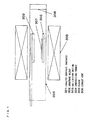
- Fig. 1 shows, as an example, a production apparatus used in the present invention.
- the production apparatus includes a tubular synthesizing furnace 304 that accommodates a substrate 301 supporting a catalyst, and a heater 305 provided around the synthesizing furnace 304.
- the heater preferably heats at not less than 400°C but not more than 1100°C. Examples of the heater encompass a resistance heater, an infrared heater and an electromagnetic induction heater.
- a substrate holder 302 for holding the substrate 301 thereon is provided in a lower part of the synthesizing furnace 304, and a gas ejection section 303 is provided above the substrate holder 302.
- the gas ejection section 303 ejects the reducing gas, the raw material gas, the inert gas, the catalyst activation material and the like to the substrate.
- a non-return valve, a flow control valve, a flow sensor and the like are provided in a part through which gases flow toward the gas ejection section 303. Opening and closing of the flow control valve are controlled as appropriate by a control device. This makes it possible to control flow volume of the reducing gas, the raw material gas, the invert gas, the catalyst activation material and the like.
- a mixture of these gases is ejected from the gas ejection section 303.
- the gas ejected from the gas ejection section 303 is naturally discharged outside the synthesizing furnace from an outlet.
- the aligned CNT aggregate is produced as follows: Firstly, the substrate 301 supporting the catalyst thereon is placed on the substrate holder 302 in the synthesizing furnace 304. Thereafter, the inert gas is ejected from the gas ejection section 303 whereby air in the synthesizing furnace 304 is replaced by the inert gas. Subsequently, in a formation step, the reducing gas is ejected from the gas ejection section 303 while the synthesizing furnace 304 is heated by the heater 305. Subsequently, in a growth step, the raw material gas and the catalyst activation material are ejected from the gas ejection section 303 while the synthesizing furnace 304 is further heated by the heater 305.
- the aligned CNT aggregate is produced on the substrate 301.
- the inert gas is ejected from the gas ejection section 303, and the heater 305 stops heating the synthesizing furnace 304.
- the synthesizing furnace 304 is cooled down to not more than 200°C.
- Means for supplying the catalyst activation material is not particularly limited. Examples of the means include supplying the catalyst activation material by use of a bubbler, supplying the catalyst activation material by vaporizing a solution containing a catalyst activation agent, supplying the catalyst activation material as it is in a gaseous state, and supplying the catalyst activation material by liquefying or vaporizing a solid catalyst activation agent. It is possible to build a supply system using various devices such as a vaporizer, a mixer, a stirrer, a diluter, a spray, a pump, and a compressor, so as to supply the catalyst activation material.
- a measurement device for measuring a concentration of the catalyst activation material may be provided in a supply tube or the like for supplying the catalyst activation material.
- a feedback control is carried out on the basis of an output obtained by the measurement device. Through feedback control using values outputted from the measuring device, stable supply of the catalyst activation material with a small number of changes over time can be ensured.
- the gas ejection section 303 is not particularly limited.
- a shower head having a plurality of nozzles formed so as to face a catalyst layer formation surface of the substrate can be used as the gas ejection section 303.
- What is meant by "so as to face” is that the nozzles are formed such that an angle made by ejection axis lines of the nozzles and a normal line of the substrate ranges from not less than 0° to less than 90°. That is, gas flow ejected from the nozzles provided in the shower head directs substantially orthogonally to the substrate.
- Fig. 2 shows an aligned CNT aggregate production apparatus in accordance with the present invention.
- the production apparatus of present invention basically includes an inlet purge section, a formation unit, a growth unit, a transfer unit, gas mixing prevention means, connection sections, a cooling unit, and an outlet purge section. The following describes how these are arranged in the production apparatus.
- the inlet purge section is a set of devices for preventing the outside air from flowing into a furnace of the apparatus through a substrate inlet, and has a function of replacing with a purge gas an environment surrounding the substrate transferred into the apparatus.
- Examples of the inlet purge section include a furnace or chamber in which the purge gas is retained, and a gas ejection section for ejecting the purge gas.
- the purge gas be an inert gas.
- the purge gas be nitrogen.
- the substrate inlet is always open as in the case where the transfer unit is a belt-conveyor type, it is preferable to use, as a purge gas ejection section, a gas curtain device that ejects the purge gas from top and bottom in the form of a shower, in order to prevent the outside air from flowing in through an inlet of the apparatus.
- a gas curtain device that ejects the purge gas from top and bottom in the form of a shower, in order to prevent the outside air from flowing in through an inlet of the apparatus.
- the formation unit is a set of devices for carrying out a formation step, and has a function of causing the catalyst formed on the surface of the substrate to be surrounded by the reducing gas environment constituted by the reducing gas, and heating at least either the catalyst or the reducing gas.
- the formation unit include a formation furnace in which the reducing gas is retained, a reducing gas ejection section for ejecting the reducing gas, and a heater for heating at least either the catalyst or the reducing gas. It is preferable that the heater be capable of heating to a temperature of 400°C to 1100°C. Examples of the heater include a resistance heater, an infrared heater, and an electromagnetic induction heater.
- the growth unit is a set of devices for carrying out a growth step, and has a function of synthesizing the aligned CNT aggregate by causing the catalyst, which has been put into a state suitable to production of the aligned CNT aggregate in the formation step, to be surrounded by the raw material environment constituted by the raw material gas, and by heating at least either the catalyst or the raw material gas.
- Specific examples of the growth unit include a growth furnace in which the environment of the raw material gas is retained, a raw material gas ejection section for ejecting the raw material gas, and a heater for heating at least either the catalyst or the raw material gas.
- the heater may be any heaters that are capable of heating at a temperature of 400°C to 1,100°C, examples of which include a resistance heater, an infrared heater, and an electromagnetic induction heater. It is preferable that the growth unit further include a section for adding the catalyst activation material.
- the section for adding the catalyst activation material is a set of devices for either adding the catalyst activation material into the raw material gas, or adding the catalyst activation material directly to the environment surrounding the catalyst in the growth furnace.
- Means for supplying the catalyst activation material is not particularly limited. Examples of the means include supplying the catalyst activation material through a bubbler, supplying the catalyst activation material by vaporizing a solution containing a catalyst activation agent, supplying the catalyst activation material as it is in a gaseous state, and supplying the catalyst activation material by liquefying or vaporizing a solid catalyst activation agent.
- the transfer unit is a set of devices necessary for transferring the substrate at least from the formation unit to the growth unit.
- An example of the transfer unit is a mesh belt and a drive device driven by a reducer-equipped electric motor in the case of a belt-conveyor type.
- the gas mixing prevention means is a set of devices that is installed at the connection sections, via which the respective inner parts of the units are spatially connected, and that performs a function of preventing gas from flowing out of a furnace space of one of the units into that of another.
- the gas mixing prevention means include a gate valve device that mechanically disconnects the spatial connection between one unit and another except when the substrate moves from one unit to another, a gas curtain device that disconnects the spatial connection by ejecting an inert gas, and an exhaust device through which gasses in the connection sections and/or those areas in the units which are near the connection sections are exhausted out of the system.
- a shutter and/or a gas curtain be used in combination with the exhaust device.
- the gas mixing prevention means needs to function such that a concentration of carbon atoms in the environment of the reducing gas in the formation furnace is kept preferably smaller than or equal to 5 ⁇ 10 22 atoms/m 3 , or more preferably smaller than or equal to 1 ⁇ 10 22 atoms/m 3 .
- each exhaust quantity Q of a plurality of exhaust sections cannot be independently determined, and need to be adjusted according to the amount of gas supplied to the whole apparatus (e.g., the flow rate of the reducing gas, the flow rate of the raw material gas, and the flow rate of a coolant gas).
- a necessary condition for gas mixing prevention to be satisfied can be represented by the following equation: Q ⁇ 4 ⁇ DS / L where D is a diffusion coefficient of a gas that needs to be prevented from flowing in, S is a sectional area of a boundary at which the gas is prevented from flowing in, and L is a length of each exhaust section (along a length of the furnace).
- the exhaust quantity of each exhaust section is set such that the conditional equation is satisfied and a balance between gas supply and gas exhaust in the whole apparatus is kept.
- Inflow of the raw material gas into the formation furnace exerts a harmful influence on the growth of the CNTs. It is preferable that the inflow of the raw material gas into the formation furnace be prevented by the gas mixing prevention means so that the concentration of carbon atoms in the environment of the reducing gas in the formation unit is kept preferably smaller than or equal to 5 ⁇ 10 22 atoms/m 3 , or more preferably smaller than or equal to 1 ⁇ 10 22 atoms/m 3 .
- the "concentration of carbon atoms" here is calculated according to Eq. (1): Eq .
- Production quantity and quality of the CNTs can be satisfactorily maintained by keeping the concentration of carbon atoms in the environment of the reducing gas in the formation furnace at not greater than 5 ⁇ 10 22 atoms/m 3 . That is, the concentration of carbon atoms of 5 ⁇ 10 22 atoms/m 3 or smaller makes it possible, in the formation step, to satisfactorily exhibit the effects of reducing the catalyst, stimulating the catalyst to become fine particles suitable for the growth of the CNTs, and improving the activity of the catalyst, whereby the production quantity and quality of the CNTs during the growth step can be satisfactorily improved.
- connection sections are a set of devices via which the respective furnace spaces of the units are spatially connected and which serve to prevent the substrate from being exposed to the outside air when it is transferred from one unit to another.
- connection sections include a furnace or chamber capable of shielding the environment surrounding the substrate from the outside air and passing the substrate from one unit to another.
- the cooling unit is a set of devices necessary for cooling down the substrate on which the aligned CNT aggregate has grown.
- the cooling unit has a function of preventing oxidation and cooling effects on the aligned CNT aggregate, the catalyst and the substrate after the growth step.
- Examples of the cooling unit include: a cooling furnace in which an inert gas is retained; a water-cooled cooling tube disposed to surround an internal space of the cooling furnace in the case of a water-cooled type; and an ejection section that ejects an inert gas into the cooling furnace in the case of an air-cooled type. Further, the water-cooled type and the air-cooled type may be used in combination.
- the outlet purge section is a set of devices for preventing the outside air from flowing into a furnace of the apparatus through a substrate outlet.
- the outlet purge section has a function of causing the environment surrounding the substrate to be an environment of a purge gas.
- Specific examples of the outlet purge section include a furnace or chamber in which the environment of the purge gas is retained, and an ejection section for ejecting the purge gas.
- the purge gas be an inert gas.
- the purge gas be nitrogen.
- the transfer unit is a belt-conveyor type
- a gas curtain device that ejects the purge gas from top and bottom in the form of a shower, in order to prevent the outside air from flowing in through an outlet of the apparatus.
- shower heads each including a plurality of nozzles provided so as to face the catalyst layer formation surface of the substrate may be used.
- face is that each of the nozzles is provided such that its ejection axis line forms an angle of not less than 0° to less than 90° with a line normal to the surface of the substrate, i.e., such that the flow direction of gas as ejected from the nozzles provided in the shower head is substantially orthogonal to the surface of the substrate.
- a formation unit 102, a growth unit 104 and a cooling unit 105 include a formation furnace 102a, a growth furnace 104a and a cooling furnace 105a, respectively.
- a transfer unit 107 includes a mesh belt 107a and a belt driving section 107b. These furnaces are spatially connected to one another via connection sections. The transfer unit 107 transfers a substrate (catalyst substrate) 111 into the formation furnace, the growth furnace and the cooling furnace in this order.
- an inlet purge section 101 which ejects the purge gas from top and bottom in the form of a shower thereby preventing the outside air from flowing into the furnace of the apparatus through the inlet.
- the inlet purge section 101 and the formation unit 102 are spatially connected to each other via the connection section in which an exhaust section 103a of the gas mixing prevention means is disposed, and through the exhaust section 103a, a mixture of the purge gas ejected from the inlet purge section 101 and the reducing gas ejected from a reducing gas ejection section 102b is discharged.
- the exhaust section 103a prevents the purge gas from flowing into the formation furnace and the reducing gas from flowing into the inlet purge section.
- the formation unit 102 and the growth unit 104 are spatially connected to each other via the connection section in which an exhaust section 103b of the gas mixing prevention means is disposed, and through the exhaust section 103b, a mixture of the reducing gas inside of the formation furnace and the raw material gas inside of the growth furnace is discharged.
- the exhaust section 103b prevents the raw material gas from flowing into the formation furnace and the reducing gas from flowing into the growth furnace.
- the growth unit 104 and the cooling unit 105 are spatially connected to each other via the connection section in which an exhaust section 103c of the gas mixing prevention means is disposed, and through the exhaust section 103c, a mixture of the raw material gas inside of the growth furnace and the inert gas inside of the cooling furnace is discharged.
- the exhaust section 103c prevents the raw material gas from flowing into the cooling furnace and the inert gas from flowing into the growth furnace.
- an outlet purge section 106 substantially identical in structure to the inlet purge section 101.
- the outlet purge section 106 ejects the purge gas from top and bottom in the form of a shower thereby preventing the outside air from flowing into the cooling furnace through the outlet.
- the transfer unit 107 is of a belt-conveyor type in which the substrate on which surface the catalyst is formed is transferred out of the formation furnace into the cooling furnace through the growth furnace by the mesh belt 107a driven by the belt driving section (driving device) 107b, for example, with use of a reducer-equipped electric motor.
- the formation furnace and the growth furnace have their respective internal spaces spatially connected via the connection section, and the growth furnace and the cooling furnace have their respective internal spaces spatially connected via the connection section, in order that the mesh belt 107a, on which the substrate has been placed, can pass out of the formation furnace into the cooling furnace through the growth furnace.
- the exhaust sections of the gas mixing prevention means described above are provided, so as to prevent gas from flowing out of one of the furnaces into another.
- a series of substrates each having the catalyst on a surface thereof is transferred by the transfer unit 107 to pass through the inlet purge section 101, the formation unit 102, the growth unit 104, the cooling unit 105, and the outlet purge section in this order.
- the catalyst is reduced in the environment of the reducing gas in the formation unit 102, and the CNTs grow on the surfaces of the substrates in the environment of the raw material gas in the growth unit 104, and then the CNTs are cooled down in the cooling unit 105.
- a material for those components of the production apparatuses is preferably heat-resistant alloys in terms of heat resistance, precision of processing, degree of flexibility of processing and cost.
- the heat-resistant alloys include heat-resistant steel, stainless steel, and nickel-based alloys.
- a heat-resistant steel refers to a steel that contains Fe in major proportions and other alloys in concentrations of not greater than 50%
- a stainless steel refers to a steel that contains Fe in major proportions, other alloys in concentrations of not greater than 50%, and approximately not less than 12% of Cr.
- the nickel-based alloys include alloys obtained by adding Mo, Cr, Fe, and the like to Ni. Specifically, SUS 310, Inconel 600, Inconel 601, Inconel 625, Incoloy 800, MC Alloy, and Haynes 230 Alloy are preferable in terms of heat resistance, mechanical strength, chemical stability, low cost and the like.
- Carbon contaminants that adhere to the wall surfaces and the like when the CNTs are synthesized in a high-carbon environment can be decreased by forming the inner walls of the furnaces and/or the components for use in the furnaces with a heat-resistant alloy and by either plating a surface of the heat-resistant alloy with molten aluminum or polishing the surface such that the surface has an arithmetic average roughness Ra ⁇ 2 ⁇ m. This favorably makes it possible to prevent a decrease in production quantity and deterioration in quality of the aligned CNT aggregates.
- Molten aluminum plating means a process of forming an aluminum or aluminum alloy layer on a surface of an object by dipping the object into a bath of molten aluminum. More specifically, the process is carried out as follows: a surface of an object (base metal) is washed (preprocessed), and then the object is dipped into a bath of molten aluminum at approximately 700°C, thereby causing the molten aluminum to disperse into the surface of the base metal so as to form an alloy of the base metal and aluminum, so that the aluminum is adhered to the alloy layer when the base metal is withdrawn from the bath. Furthermore, the molten aluminum plating also encompasses a post-dipping process in which a Fe-Al alloy layer under the surface layer (the alumina layer and aluminum surface layer) is exposed by subjecting the surface layer to low-temperature thermal diffusion.
- Examples of the method for polishing the heat-resistant alloy such that an arithmetic average roughness of the heat-resistant alloy is Ra ⁇ 2 ⁇ m include: mechanical polishing, which is typified by buffing; chemical polishing, which involves the use of a chemical; electrolytic polishing, which is carried out while passing an electric current through an electrolyte; and complex electrolytic polishing, which is a combination of mechanical polishing and electrolytic polishing.
- the present invention is not limited to the description of the preferred embodiments above, but may be applied in many variations within the scope of gist thereof.
- reaction conditions such as raw material gas and heating temperature
- the catalyst is formed onto the surface of the substrate by a film-forming apparatus provided separately from the production apparatus
- the production apparatus may be configured such that a catalyst layer-forming unit is provided upstream of the formation unit so that a base substrate passes through the catalyst layer-forming unit before it passes through the formation unit.
- the formation, growth and cooling units are arranged in this order and have their respective furnace spaces spatially connected via the connection sections, a plurality of units that process steps other than the formation, growth and cooling steps may be further provided somewhere and have their respective furnace spaces spatially connected via connection sections.
- the belt-conveyor type has been described as a type of transfer unit, the present invention is not limited to this.
- a robot-arm type, a turntable type or a lifting-and-lowering type may be employed.
- the term "specific surface area” means a value obtained from an adsorption and desorption isotherm of liquid nitrogen at 77K using the Brunauer-Emmett-Teller equation. The specific surface area was measured by use of a BET specific surface area measuring apparatus (HM model-1210; manufactured by MOUNTECH Co., Ltd.).
- G/D ratio means an index that is commonly used to evaluate the quality of CNTs.
- vibration modes called “G band” (near 1,600 cm -1 ) and “D band” (near 1,350 cm -1 ) are observed.
- the G band is a vibration mode based on hexagonal lattice structures of graphite appearing as cylindrical surfaces of the CNTs
- the D band is a vibration mode based on crystal defects. Therefore, with a higher peak intensity ratio of the G band to the D band (G/D ratio), the CNTs can be evaluated to be higher in quality and lower in defect rate.
- the G/D ratio was calculated by peeling off a part of an aligned CNT aggregate located near the center of a substrate and measuring a raman spectrum through irradiation with a laser of that surface of the aligned CNT aggregate which had been peeled off from the substrate, by use of a microscopic laser raman system (Nicolet Almega XR; manufactured by Thermo Fisher Scientific K.K.).
- a surface roughness of the present invention is an arithmetic average roughness Ra.
- the value of Ra was calculated under the following measurement condition by use of a laser microscope (VK-9710 manufactured by
- a base substrate used was Fe-Ni-Cr alloy YEF 426 (Ni 42%, Cr 6%; manufactured by Hitachi Metals, Ltd.) having a size of 40 mm ⁇ 40 mm with a thickness of 0.3 mm.
- a surface roughness of the base substrate was measured by use of a laser microscope, and it was found that an arithmetic average roughness of the base substrate was Ra ⁇ 2.1 ⁇ m.
- Alumina layers with a thickness of 100 nm were formed on both front and back surfaces of the base substrate by use of a sputtering apparatus. Then, an iron layer (catalyst metal layer) with a thickness of 1.0 nm was formed only on the front surface of the base substrate by use of the sputtering apparatus.
- Fig. 1 shows a production apparatus of the present example.
- the substrate supporting the catalyst thereon was placed on a substrate holder in a synthesizing furnace adjusted to have a room temperature and a furnace pressure of 1.02E+5.
- 4000 sccm of nitrogen was introduced into the synthesizing furnace from a gas ejection section for 4 minutes, so that air in the synthesizing furnace was replaced by nitrogen.
- 400 sccm of nitrogen and 3600 sccm of hydrogen were introduced into the synthesizing furnace from the gas ejection section for 30 minutes while the synthesizing furnace was heated up to 800°C at a heating-up rate of 26°C/minute (formation step).
- a mixed gas of 880 sccm of nitrogen, 100 sccm of ethylene, and 20 sccm of water-containing nitrogen (moisture content 12,000 ppmv) was ejected from the gas ejection section for 10 minutes into the synthesizing furnace adjusted to constantly have a temperature of 800°C and the furnace pressure of 1.02E+5 (growth process).
- 4000 sccm of nitrogen was introduced into the synthesizing furnace from the gas ejection section while the synthesizing furnace was naturally cooled down to not more than 200°C (cooling step).
- the synthesizing furnace, the substrate holder and the gas ejection section were made from SUS310S, and surfaces thereof were plated with molten aluminum.
- the surfaces had an arithmetic average roughness Ra of 3.4 ⁇ m to 8.0 ⁇ m (the surface roughness was measured within 236 ⁇ m in z direction).
- the surfaces were plated with molten aluminum as follows:
- An aligned CNT aggregate was continuously produced under the above-described conditions. Although properties of the aligned CNT aggregate that is produced according to the present example depends on the details of production conditions, the aligned CNT aggregate typically had a density of 0.03 g/cm 3 , a BET-specific surface area of 1,100 m 2 /g, an average external diameter of 2.9 nm, a half width of 2 nm, a carbon purity of 99.9%, and a Herman's orientation factor of 0.7. Table 1 shows results of production quantity, specific surface area and G/D ratio of the continuously produced aligned CNT aggregates.
- a base substrate used was Fe-Ni-Cr alloy YEF 426 (Ni 42%, Cr 6%; manufactured by Hitachi Metals, Ltd.) having a size of 90 mm ⁇ 90 mm with a thickness of 0.3 mm.
- a surface roughness of the base substrate was measured by use of the laser microscope, and it was found that an arithmetic average roughness of the base substrate was Ra ⁇ 2.1 ⁇ m.
- Alumina layers with a thickness of 20 nm were formed on both front and back surfaces of the base substrate by use of the sputtering apparatus. Then, an iron layer (catalyst metal layer) with a thickness of 1.0 nm was formed only on the front surface of the base substrate by use of the sputtering apparatus.
- Fig. 2 shows a production apparatus of the present example.
- the production apparatus included an inlet purge section 101, a formation unit 102, gas mixing prevention means 103, a growth unit 104, a cooling unit 105, an outlet purge section 106, a transfer unit 107, and connection sections 108 to 110.
- the catalyst substrate thus prepared was placed on a mesh belt in the production apparatus, and transferred at various transfer rates by the mesh belt to be subjected to the formation, growth, and cooling steps in this order, whereby the aligned CNT aggregates were produced.
- Furnaces and ejection sections of the formation and growth units, the exhaust sections of the gas mixing prevention means, the mesh belt, the connection sections were made from SUS310, and surfaces thereof were plated with molten aluminum.
- the surfaces had an arithmetic average roughness Ra of 3.4 ⁇ m to 8.0 ⁇ m (the surface roughness was measured within 316 ⁇ m in z direction). Plating the surfaces with molten aluminum was carried out in the same manner as in Example 1.
- the aligned CNT aggregate typically had a density of 0.03 g/cm 3 , a BET-specific surface area of 1,100 m 2 /g, an average external diameter of 2.9 nm, a half width of 2 nm, a carbon purity of 99.9%, and a Herman's orientation factor of 0.7.
- Table 2 shows results of production quantity, specific surface area and G/D ratio of the continuously produced aligned CNT aggregates.
- the reducing gas was sampled through a gas sampling port installed near the reducing gas ejection section, and the constitution of the sample was analyzed by an FTIR analyzer (Nicolet 6700 FT-IR; manufactured by Thermo Fisher Scientific K.K.). As a result, it was confirmed that the concentration of ethylene in the formation furnace was kept at 50 ppm by the gas mixing prevention means. This concentration is translated into a concentration of carbon atoms of approximately 3 ⁇ 10 21 atoms/m 3 .
- the conditions for producing a substrate supporting a catalyst is identical to those in Example 1. Further, the production device and the production conditions of the present example are identical to those in Example 1 except materials of the synthesizing furnace, the substrate holder and the gas ejection section, and surface treatment thereof.
- the synthesizing furnace, the substrate holder and the gas ejection section of the present example were made from Inconel 601, and surfaces thereof were sandblasted, and polished by a sand paper or a polishing agent so as to have an arithmetic average roughness Ra of 1.4 ⁇ m to 1.9 ⁇ m (the surface roughness was measured within 293 ⁇ m in z direction).
- An aligned CNT aggregate was continuously produced under the above conditions. Although properties of the aligned CNT aggregate that is produced according to the present example depends on the details of production conditions, a typical aligned CNT aggregate had a density of 0.03 g/cm 3 , a BET-specific surface area of 1,100 m 2 /g, an average external diameter of 2.9 nm, a half width of 2 nm, a carbon purity of 99.9%, and a Herman's orientation factor of 0.7. Table 3 shows results of production quantity, specific surface area and G/D ratio of the continuously produced aligned CNT aggregates.
- the conditions for producing a substrate supporting a catalyst is identical to those in Example 2. Further, the production device and the production conditions of the present example are identical to those in Example 2 except materials of the furnaces and the ejection sections of the formation and growth units, the exhaust sections of the gas mixing prevention means, the mesh belt and the connection sections, and surface treatment thereof.
- the furnaces and the ejection sections of the formation and growth units, the exhaust sections of the gas mixing prevention means, the mesh belt, and the connection sections of the present example were made from Inconel 601, and surfaces thereof were sandblasted, and polished by a sand paper or a polishing agent so as to have an arithmetic average roughness Ra of 1.4 ⁇ m to 1.9 ⁇ m (the surface roughness was measured within 293 ⁇ m in z direction).
- An aligned CNT aggregate was continuously produced under the above conditions. Although properties of the aligned CNT aggregate that is produced according to the present example depends on the details of production conditions, a typical aligned CNT aggregate had a density of 0.03 g/cm 3 , a BET-specific surface area of 1,100 m 2 /g, an average external diameter of 2.9 nm, a half width of 2 nm, a carbon purity of 99.9%, and a Herman's orientation factor of 0.7. Table 4 shows results of production quantity, specific surface area and G/D ratio of the continuously produced aligned CNT aggregates.
- the reducing gas was sampled through a gas sampling port installed near the reducing gas ejection section, and the constitution of the sample was analyzed by an FTIR analyzer (Nicolet 6700 FT-IR; manufactured by Thermo Fisher Scientific K.K.). As a result, it was confirmed that the concentration of ethylene in the formation furnace was kept at 50 ppm by the gas mixing prevention means. This concentration is translated into a concentration of carbon atoms of approximately 3 ⁇ 10 21 atoms/m 3 .
- the conditions for producing a substrate supporting a catalyst is identical to those in Example 1.
- the production device and the production conditions of the present comparative example are identical to those in Example 1 except materials of the synthesizing furnace, the substrate holder and the gas ejection section, and surface treatment thereof.
- the synthesizing furnace, the substrate holder and the gas ejection section of the present comparative example were made from Inconel 601, and surfaces thereof were sandblasted so as to have an arithmetic average roughness Ra of 3.2 ⁇ m to 4.1 ⁇ m (the surface roughness was measured within 364 ⁇ m in z direction).
- Table 5 shows results of production quantity, specific surface area and G/D ratio of the continuously produced aligned CNT aggregates.
- the apparatus of the present invention for producing the aligned carbon nanotube aggregates may include: a formation unit for causing the catalyst to be surrounded by the reducing gas environment constituted by the reducing gas, and heating at least either the catalyst or the reducing gas; a growth unit for growing the aligned carbon nanotube aggregate by causing the catalyst to be surrounded by the raw material gas environment constituted by the raw material gas, and heating at least either the catalyst or the raw material gas; and a transfer unit for transferring the substrate at least from the formation unit to the growth unit.
- the apparatus of the present invention for producing the aligned carbon nanotube aggregates may include a formation unit for causing the catalyst to be surrounded by the reducing gas environment constituted by the reducing gas, and heating at least either the catalyst or the reducing gas; a growth unit for growing the aligned carbon nanotube aggregate by causing the catalyst to be surrounded by the raw material gas environment constituted by the raw material gas, and heating at least either the catalyst or the raw material gas; and a transfer unit for transferring the substrate at least from the formation unit to the growth unit.
- the present invention makes it possible to prevent a decrease in production quantity and deterioration in quality of aligned CNT aggregates in serial production, and makes it easy to increase the size of a production apparatus, thereby being suitably applicable to fields of electronic device materials, optical element materials, conducting materials and like materials.
Landscapes
- Chemical & Material Sciences (AREA)
- Engineering & Computer Science (AREA)
- Organic Chemistry (AREA)
- Nanotechnology (AREA)
- Materials Engineering (AREA)
- Chemical Kinetics & Catalysis (AREA)
- Inorganic Chemistry (AREA)
- Physics & Mathematics (AREA)
- General Health & Medical Sciences (AREA)
- Toxicology (AREA)
- Health & Medical Sciences (AREA)
- Crystallography & Structural Chemistry (AREA)
- General Physics & Mathematics (AREA)
- Condensed Matter Physics & Semiconductors (AREA)
- Electromagnetism (AREA)
- General Chemical & Material Sciences (AREA)
- Mechanical Engineering (AREA)
- Metallurgy (AREA)
- Manufacturing & Machinery (AREA)
- Composite Materials (AREA)
- Carbon And Carbon Compounds (AREA)
Applications Claiming Priority (2)
| Application Number | Priority Date | Filing Date | Title |
|---|---|---|---|
| JP2009029128 | 2009-02-10 | ||
| PCT/JP2010/000743 WO2010092787A1 (ja) | 2009-02-10 | 2010-02-08 | カーボンナノチューブ配向集合体の製造装置 |
Publications (3)
| Publication Number | Publication Date |
|---|---|
| EP2397441A1 true EP2397441A1 (de) | 2011-12-21 |
| EP2397441A4 EP2397441A4 (de) | 2015-12-02 |
| EP2397441B1 EP2397441B1 (de) | 2022-11-09 |
Family
ID=42561637
Family Applications (1)
| Application Number | Title | Priority Date | Filing Date |
|---|---|---|---|
| EP10741067.2A Active EP2397441B1 (de) | 2009-02-10 | 2010-02-08 | Vorrichtung zur herstellung eines ausgerichteten kohlenstoffnanoröhrchenaggregats |
Country Status (6)
| Country | Link |
|---|---|
| US (2) | US9598285B2 (de) |
| EP (1) | EP2397441B1 (de) |
| JP (1) | JP5574265B2 (de) |
| KR (1) | KR101711676B1 (de) |
| CN (1) | CN102307808B (de) |
| WO (1) | WO2010092787A1 (de) |
Cited By (2)
| Publication number | Priority date | Publication date | Assignee | Title |
|---|---|---|---|---|
| EP2716600A4 (de) * | 2011-05-31 | 2015-03-04 | Zeon Corp | Vorrichtung zur herstellung eines orientieren kohlenstoffnanoröhrchenaggregats |
| FR3050449A1 (fr) * | 2016-04-25 | 2017-10-27 | Nawatechnologies | Installation pour la fabrication d'un materiau composite comprenant des nanotubes de carbone, et procede de mise en oeuvre de cette installation |
Families Citing this family (14)
| Publication number | Priority date | Publication date | Assignee | Title |
|---|---|---|---|---|
| NO2749379T3 (de) | 2012-04-16 | 2018-07-28 | ||
| EP2838837A4 (de) | 2012-04-16 | 2015-12-23 | Seerstone Llc | Verfahren und strukturen zur reduzierung von kohlenstoffoxiden mit eisenlosen katalysatoren |
| CN104321274B (zh) * | 2012-04-16 | 2017-04-26 | 赛尔斯通股份有限公司 | 用于在碳氧化物催化转化器中使用金属催化剂的方法 |
| EP2838844A4 (de) | 2012-04-16 | 2015-10-28 | Seerstone Llc | Verfahren zur behandlung abgashaltiger kohlenstoffoxide |
| US9815698B2 (en) * | 2012-12-20 | 2017-11-14 | Zeon Corporation | Method of manufacturing carbon nanotubes |
| KR20160024871A (ko) * | 2013-06-27 | 2016-03-07 | 니폰 제온 가부시키가이샤 | 카본 나노튜브의 제조 방법 |
| JP6422149B2 (ja) * | 2014-07-01 | 2018-11-14 | 国立大学法人静岡大学 | カーボンナノチューブの表面処理方法 |
| JP6476759B2 (ja) * | 2014-10-31 | 2019-03-06 | 日本ゼオン株式会社 | カーボンナノチューブ配向集合体の製造方法 |
| CN107381538B (zh) * | 2016-05-17 | 2019-10-25 | 北京睿曼科技有限公司 | 一种碳纳米管的制备方法 |
| CN107381539B (zh) * | 2016-05-17 | 2019-10-25 | 北京睿曼科技有限公司 | 一种阵列碳纳米薄膜的制备方法 |
| WO2018022999A1 (en) | 2016-07-28 | 2018-02-01 | Seerstone Llc. | Solid carbon products comprising compressed carbon nanotubes in a container and methods of forming same |
| JP6912904B2 (ja) * | 2017-03-09 | 2021-08-04 | 大陽日酸株式会社 | カーボンナノチューブの製造方法、カーボンナノチューブ、及び配向カーボンナノチューブ付き基材 |
| JP7015641B2 (ja) * | 2017-04-26 | 2022-02-15 | 大陽日酸株式会社 | 炭素系微細構造物、及び炭素系微細構造物の製造方法 |
| CA3053093A1 (en) * | 2017-03-09 | 2018-09-13 | Taiyo Nippon Sanso Corporation | Carbon nanotube, carbon-based fine structure, and substrate having carbon nanotube, and method respectively for producing these products |
Family Cites Families (19)
| Publication number | Priority date | Publication date | Assignee | Title |
|---|---|---|---|---|
| US5747119A (en) * | 1993-02-05 | 1998-05-05 | Kabushiki Kaisha Toshiba | Vapor deposition method and apparatus |
| US5711821A (en) * | 1995-04-13 | 1998-01-27 | Texas Instruments Incorporated | Cleansing process for wafer handling implements |
| US6303501B1 (en) * | 2000-04-17 | 2001-10-16 | Applied Materials, Inc. | Gas mixing apparatus and method |
| JP4717179B2 (ja) * | 2000-06-21 | 2011-07-06 | 日本電気株式会社 | ガス供給装置及び処理装置 |
| JP2002222767A (ja) * | 2001-01-26 | 2002-08-09 | Seiko Epson Corp | 真空装置用治具の形成方法 |
| JP3768867B2 (ja) | 2001-12-03 | 2006-04-19 | 株式会社リコー | カーボンナノチューブの作製方法 |
| US20040089237A1 (en) * | 2002-07-17 | 2004-05-13 | Pruett James Gary | Continuous chemical vapor deposition process and process furnace |
| GB0329460D0 (en) * | 2003-12-19 | 2004-01-28 | Oxford Instr Plasma Technology | Apparatus and method for plasma processing |
| US20050238810A1 (en) * | 2004-04-26 | 2005-10-27 | Mainstream Engineering Corp. | Nanotube/metal substrate composites and methods for producing such composites |
| JP4548014B2 (ja) | 2004-06-30 | 2010-09-22 | 日立造船株式会社 | カーボンナノチューブの連続製造方法およびその装置 |
| US20080274036A1 (en) | 2005-06-28 | 2008-11-06 | Resasco Daniel E | Microstructured catalysts and methods of use for producing carbon nanotubes |
| JP5443756B2 (ja) * | 2005-06-28 | 2014-03-19 | ザ ボード オブ リージェンツ オブ ザ ユニバーシティ オブ オクラホマ | カーボンナノチューブを成長および収集するための方法 |
| JP4832046B2 (ja) | 2005-09-30 | 2011-12-07 | 日立造船株式会社 | 連続熱cvd装置 |
| JP2007091556A (ja) | 2005-09-30 | 2007-04-12 | Hitachi Zosen Corp | カーボン系薄膜の連続製造装置 |
| GB0611485D0 (en) * | 2006-06-09 | 2006-07-19 | Statoil Asa | Method |
| JP5339281B2 (ja) | 2007-02-05 | 2013-11-13 | 独立行政法人産業技術総合研究所 | 配向カーボンナノチューブの製造装置 |
| US8128750B2 (en) * | 2007-03-29 | 2012-03-06 | Lam Research Corporation | Aluminum-plated components of semiconductor material processing apparatuses and methods of manufacturing the components |
| US8568555B2 (en) * | 2007-03-30 | 2013-10-29 | Tokyo Electron Limited | Method and apparatus for reducing substrate temperature variability |
| US8016945B2 (en) * | 2007-12-21 | 2011-09-13 | Applied Materials, Inc. | Hafnium oxide ALD process |
-
2010
- 2010-02-08 JP JP2010550447A patent/JP5574265B2/ja active Active
- 2010-02-08 CN CN2010800071399A patent/CN102307808B/zh active Active
- 2010-02-08 WO PCT/JP2010/000743 patent/WO2010092787A1/ja not_active Ceased
- 2010-02-08 KR KR1020117018653A patent/KR101711676B1/ko active Active
- 2010-02-08 US US13/148,619 patent/US9598285B2/en active Active
- 2010-02-08 EP EP10741067.2A patent/EP2397441B1/de active Active
-
2016
- 2016-03-30 US US15/085,586 patent/US20160207771A1/en not_active Abandoned
Non-Patent Citations (1)
| Title |
|---|
| See references of WO2010092787A1 * |
Cited By (4)
| Publication number | Priority date | Publication date | Assignee | Title |
|---|---|---|---|---|
| EP2716600A4 (de) * | 2011-05-31 | 2015-03-04 | Zeon Corp | Vorrichtung zur herstellung eines orientieren kohlenstoffnanoröhrchenaggregats |
| FR3050449A1 (fr) * | 2016-04-25 | 2017-10-27 | Nawatechnologies | Installation pour la fabrication d'un materiau composite comprenant des nanotubes de carbone, et procede de mise en oeuvre de cette installation |
| WO2017187080A1 (fr) | 2016-04-25 | 2017-11-02 | Nawatechnologies | Installation pour la fabrication d'un matériau composite comprenant des nanotubes de carbone, et procédé de mise en oeuvre de cette installation |
| US11358867B2 (en) | 2016-04-25 | 2022-06-14 | Nawatechnologies | Facility for producing a composite material comprising carbon nanotubes, and method for implementing said facility |
Also Published As
| Publication number | Publication date |
|---|---|
| KR20110116028A (ko) | 2011-10-24 |
| CN102307808A (zh) | 2012-01-04 |
| EP2397441A4 (de) | 2015-12-02 |
| US9598285B2 (en) | 2017-03-21 |
| JPWO2010092787A1 (ja) | 2012-08-16 |
| WO2010092787A1 (ja) | 2010-08-19 |
| EP2397441B1 (de) | 2022-11-09 |
| US20110308462A1 (en) | 2011-12-22 |
| US20160207771A1 (en) | 2016-07-21 |
| JP5574265B2 (ja) | 2014-08-20 |
| KR101711676B1 (ko) | 2017-03-02 |
| CN102307808B (zh) | 2013-07-10 |
Similar Documents
| Publication | Publication Date | Title |
|---|---|---|
| US9598285B2 (en) | Apparatus for producing aligned carbon nanotube aggregates | |
| EP2263974B1 (de) | Vorrichtung und verfahren zur herstellung ausgerichteter kohlenstoffnanoröhrchenaggregate | |
| US9682863B2 (en) | Method for producing aligned carbon nanotube assembly | |
| EP2397440B1 (de) | Substrat zur herstellung ausgerichteter kohlenstoffnanoröhrchenaggregate sowie verfahren zur herstellung ausgerichteter kohlenstoffnanoröhrchenaggregate | |
| JP5590603B2 (ja) | カーボンナノチューブ配向集合体の製造装置 | |
| EP2716600A1 (de) | Vorrichtung zur herstellung eines orientieren kohlenstoffnanoröhrchenaggregats | |
| EP2937312B1 (de) | Verfahren zur herstellung von kohlenstoffnanoröhrchen | |
| JP5700819B2 (ja) | カーボンナノチューブ配向集合体の製造方法 | |
| JP5622101B2 (ja) | カーボンナノチューブ配向集合体の製造方法 | |
| JP2012218953A (ja) | カーボンナノチューブ配向集合体の製造方法 |
Legal Events
| Date | Code | Title | Description |
|---|---|---|---|
| PUAI | Public reference made under article 153(3) epc to a published international application that has entered the european phase |
Free format text: ORIGINAL CODE: 0009012 |
|
| 17P | Request for examination filed |
Effective date: 20110907 |
|
| AK | Designated contracting states |
Kind code of ref document: A1 Designated state(s): AT BE BG CH CY CZ DE DK EE ES FI FR GB GR HR HU IE IS IT LI LT LU LV MC MK MT NL NO PL PT RO SE SI SK SM TR |
|
| DAX | Request for extension of the european patent (deleted) | ||
| RA4 | Supplementary search report drawn up and despatched (corrected) |
Effective date: 20151030 |
|
| RIC1 | Information provided on ipc code assigned before grant |
Ipc: B01J 19/02 20060101ALI20151026BHEP Ipc: C01B 31/02 20060101AFI20151026BHEP |
|
| STAA | Information on the status of an ep patent application or granted ep patent |
Free format text: STATUS: EXAMINATION IS IN PROGRESS |
|
| 17Q | First examination report despatched |
Effective date: 20210604 |
|
| REG | Reference to a national code |
Ref country code: DE Ref legal event code: R079 Ref document number: 602010068566 Country of ref document: DE Free format text: PREVIOUS MAIN CLASS: C01B0031020000 Ipc: B01J0019020000 |
|
| GRAP | Despatch of communication of intention to grant a patent |
Free format text: ORIGINAL CODE: EPIDOSNIGR1 |
|
| RIC1 | Information provided on ipc code assigned before grant |
Ipc: C01B 32/158 20170101ALI20220629BHEP Ipc: B01J 19/02 20060101AFI20220629BHEP |
|
| STAA | Information on the status of an ep patent application or granted ep patent |
Free format text: STATUS: GRANT OF PATENT IS INTENDED |
|
| INTG | Intention to grant announced |
Effective date: 20220804 |
|
| GRAS | Grant fee paid |
Free format text: ORIGINAL CODE: EPIDOSNIGR3 |
|
| GRAA | (expected) grant |
Free format text: ORIGINAL CODE: 0009210 |
|
| STAA | Information on the status of an ep patent application or granted ep patent |
Free format text: STATUS: THE PATENT HAS BEEN GRANTED |
|
| AK | Designated contracting states |
Kind code of ref document: B1 Designated state(s): AT BE BG CH CY CZ DE DK EE ES FI FR GB GR HR HU IE IS IT LI LT LU LV MC MK MT NL NO PL PT RO SE SI SK SM TR |
|
| REG | Reference to a national code |
Ref country code: GB Ref legal event code: FG4D |
|
| REG | Reference to a national code |
Ref country code: CH Ref legal event code: EP Ref country code: AT Ref legal event code: REF Ref document number: 1529998 Country of ref document: AT Kind code of ref document: T Effective date: 20221115 |
|
| REG | Reference to a national code |
Ref country code: DE Ref legal event code: R096 Ref document number: 602010068566 Country of ref document: DE |
|
| REG | Reference to a national code |
Ref country code: IE Ref legal event code: FG4D |
|
| REG | Reference to a national code |
Ref country code: LT Ref legal event code: MG9D |
|
| REG | Reference to a national code |
Ref country code: AT Ref legal event code: MK05 Ref document number: 1529998 Country of ref document: AT Kind code of ref document: T Effective date: 20221109 |
|
| PG25 | Lapsed in a contracting state [announced via postgrant information from national office to epo] |
Ref country code: SE Free format text: LAPSE BECAUSE OF FAILURE TO SUBMIT A TRANSLATION OF THE DESCRIPTION OR TO PAY THE FEE WITHIN THE PRESCRIBED TIME-LIMIT Effective date: 20221109 Ref country code: PT Free format text: LAPSE BECAUSE OF FAILURE TO SUBMIT A TRANSLATION OF THE DESCRIPTION OR TO PAY THE FEE WITHIN THE PRESCRIBED TIME-LIMIT Effective date: 20230309 Ref country code: NO Free format text: LAPSE BECAUSE OF FAILURE TO SUBMIT A TRANSLATION OF THE DESCRIPTION OR TO PAY THE FEE WITHIN THE PRESCRIBED TIME-LIMIT Effective date: 20230209 Ref country code: LT Free format text: LAPSE BECAUSE OF FAILURE TO SUBMIT A TRANSLATION OF THE DESCRIPTION OR TO PAY THE FEE WITHIN THE PRESCRIBED TIME-LIMIT Effective date: 20221109 Ref country code: FI Free format text: LAPSE BECAUSE OF FAILURE TO SUBMIT A TRANSLATION OF THE DESCRIPTION OR TO PAY THE FEE WITHIN THE PRESCRIBED TIME-LIMIT Effective date: 20221109 Ref country code: ES Free format text: LAPSE BECAUSE OF FAILURE TO SUBMIT A TRANSLATION OF THE DESCRIPTION OR TO PAY THE FEE WITHIN THE PRESCRIBED TIME-LIMIT Effective date: 20221109 Ref country code: AT Free format text: LAPSE BECAUSE OF FAILURE TO SUBMIT A TRANSLATION OF THE DESCRIPTION OR TO PAY THE FEE WITHIN THE PRESCRIBED TIME-LIMIT Effective date: 20221109 |
|
| PG25 | Lapsed in a contracting state [announced via postgrant information from national office to epo] |
Ref country code: PL Free format text: LAPSE BECAUSE OF FAILURE TO SUBMIT A TRANSLATION OF THE DESCRIPTION OR TO PAY THE FEE WITHIN THE PRESCRIBED TIME-LIMIT Effective date: 20221109 Ref country code: LV Free format text: LAPSE BECAUSE OF FAILURE TO SUBMIT A TRANSLATION OF THE DESCRIPTION OR TO PAY THE FEE WITHIN THE PRESCRIBED TIME-LIMIT Effective date: 20221109 Ref country code: IS Free format text: LAPSE BECAUSE OF FAILURE TO SUBMIT A TRANSLATION OF THE DESCRIPTION OR TO PAY THE FEE WITHIN THE PRESCRIBED TIME-LIMIT Effective date: 20230309 Ref country code: HR Free format text: LAPSE BECAUSE OF FAILURE TO SUBMIT A TRANSLATION OF THE DESCRIPTION OR TO PAY THE FEE WITHIN THE PRESCRIBED TIME-LIMIT Effective date: 20221109 Ref country code: GR Free format text: LAPSE BECAUSE OF FAILURE TO SUBMIT A TRANSLATION OF THE DESCRIPTION OR TO PAY THE FEE WITHIN THE PRESCRIBED TIME-LIMIT Effective date: 20230210 |
|
| P01 | Opt-out of the competence of the unified patent court (upc) registered |
Effective date: 20230504 |
|
| PG25 | Lapsed in a contracting state [announced via postgrant information from national office to epo] |
Ref country code: NL Free format text: LAPSE BECAUSE OF FAILURE TO SUBMIT A TRANSLATION OF THE DESCRIPTION OR TO PAY THE FEE WITHIN THE PRESCRIBED TIME-LIMIT Effective date: 20221109 |
|
| PG25 | Lapsed in a contracting state [announced via postgrant information from national office to epo] |
Ref country code: SM Free format text: LAPSE BECAUSE OF FAILURE TO SUBMIT A TRANSLATION OF THE DESCRIPTION OR TO PAY THE FEE WITHIN THE PRESCRIBED TIME-LIMIT Effective date: 20221109 Ref country code: RO Free format text: LAPSE BECAUSE OF FAILURE TO SUBMIT A TRANSLATION OF THE DESCRIPTION OR TO PAY THE FEE WITHIN THE PRESCRIBED TIME-LIMIT Effective date: 20221109 Ref country code: EE Free format text: LAPSE BECAUSE OF FAILURE TO SUBMIT A TRANSLATION OF THE DESCRIPTION OR TO PAY THE FEE WITHIN THE PRESCRIBED TIME-LIMIT Effective date: 20221109 Ref country code: DK Free format text: LAPSE BECAUSE OF FAILURE TO SUBMIT A TRANSLATION OF THE DESCRIPTION OR TO PAY THE FEE WITHIN THE PRESCRIBED TIME-LIMIT Effective date: 20221109 Ref country code: CZ Free format text: LAPSE BECAUSE OF FAILURE TO SUBMIT A TRANSLATION OF THE DESCRIPTION OR TO PAY THE FEE WITHIN THE PRESCRIBED TIME-LIMIT Effective date: 20221109 |
|
| REG | Reference to a national code |
Ref country code: DE Ref legal event code: R097 Ref document number: 602010068566 Country of ref document: DE |
|
| PG25 | Lapsed in a contracting state [announced via postgrant information from national office to epo] |
Ref country code: SK Free format text: LAPSE BECAUSE OF FAILURE TO SUBMIT A TRANSLATION OF THE DESCRIPTION OR TO PAY THE FEE WITHIN THE PRESCRIBED TIME-LIMIT Effective date: 20221109 |
|
| PLBE | No opposition filed within time limit |
Free format text: ORIGINAL CODE: 0009261 |
|
| STAA | Information on the status of an ep patent application or granted ep patent |
Free format text: STATUS: NO OPPOSITION FILED WITHIN TIME LIMIT |
|
| PG25 | Lapsed in a contracting state [announced via postgrant information from national office to epo] |
Ref country code: MC Free format text: LAPSE BECAUSE OF FAILURE TO SUBMIT A TRANSLATION OF THE DESCRIPTION OR TO PAY THE FEE WITHIN THE PRESCRIBED TIME-LIMIT Effective date: 20221109 |
|
| REG | Reference to a national code |
Ref country code: CH Ref legal event code: PL |
|
| 26N | No opposition filed |
Effective date: 20230810 |
|
| REG | Reference to a national code |
Ref country code: BE Ref legal event code: MM Effective date: 20230228 |
|
| PG25 | Lapsed in a contracting state [announced via postgrant information from national office to epo] |
Ref country code: LU Free format text: LAPSE BECAUSE OF NON-PAYMENT OF DUE FEES Effective date: 20230208 Ref country code: LI Free format text: LAPSE BECAUSE OF NON-PAYMENT OF DUE FEES Effective date: 20230228 Ref country code: CH Free format text: LAPSE BECAUSE OF NON-PAYMENT OF DUE FEES Effective date: 20230228 |
|
| PG25 | Lapsed in a contracting state [announced via postgrant information from national office to epo] |
Ref country code: SI Free format text: LAPSE BECAUSE OF FAILURE TO SUBMIT A TRANSLATION OF THE DESCRIPTION OR TO PAY THE FEE WITHIN THE PRESCRIBED TIME-LIMIT Effective date: 20221109 |
|
| REG | Reference to a national code |
Ref country code: IE Ref legal event code: MM4A |
|
| PG25 | Lapsed in a contracting state [announced via postgrant information from national office to epo] |
Ref country code: IE Free format text: LAPSE BECAUSE OF NON-PAYMENT OF DUE FEES Effective date: 20230208 |
|
| PG25 | Lapsed in a contracting state [announced via postgrant information from national office to epo] |
Ref country code: BE Free format text: LAPSE BECAUSE OF NON-PAYMENT OF DUE FEES Effective date: 20230228 |
|
| PG25 | Lapsed in a contracting state [announced via postgrant information from national office to epo] |
Ref country code: IT Free format text: LAPSE BECAUSE OF FAILURE TO SUBMIT A TRANSLATION OF THE DESCRIPTION OR TO PAY THE FEE WITHIN THE PRESCRIBED TIME-LIMIT Effective date: 20221109 |
|
| PG25 | Lapsed in a contracting state [announced via postgrant information from national office to epo] |
Ref country code: BG Free format text: LAPSE BECAUSE OF FAILURE TO SUBMIT A TRANSLATION OF THE DESCRIPTION OR TO PAY THE FEE WITHIN THE PRESCRIBED TIME-LIMIT Effective date: 20221109 |
|
| PG25 | Lapsed in a contracting state [announced via postgrant information from national office to epo] |
Ref country code: BG Free format text: LAPSE BECAUSE OF FAILURE TO SUBMIT A TRANSLATION OF THE DESCRIPTION OR TO PAY THE FEE WITHIN THE PRESCRIBED TIME-LIMIT Effective date: 20221109 |
|
| PG25 | Lapsed in a contracting state [announced via postgrant information from national office to epo] |
Ref country code: CY Free format text: LAPSE BECAUSE OF FAILURE TO SUBMIT A TRANSLATION OF THE DESCRIPTION OR TO PAY THE FEE WITHIN THE PRESCRIBED TIME-LIMIT; INVALID AB INITIO Effective date: 20100208 |
|
| PG25 | Lapsed in a contracting state [announced via postgrant information from national office to epo] |
Ref country code: HU Free format text: LAPSE BECAUSE OF FAILURE TO SUBMIT A TRANSLATION OF THE DESCRIPTION OR TO PAY THE FEE WITHIN THE PRESCRIBED TIME-LIMIT; INVALID AB INITIO Effective date: 20100208 |
|
| PG25 | Lapsed in a contracting state [announced via postgrant information from national office to epo] |
Ref country code: TR Free format text: LAPSE BECAUSE OF FAILURE TO SUBMIT A TRANSLATION OF THE DESCRIPTION OR TO PAY THE FEE WITHIN THE PRESCRIBED TIME-LIMIT Effective date: 20221109 |
|
| PGFP | Annual fee paid to national office [announced via postgrant information from national office to epo] |
Ref country code: FR Payment date: 20251231 Year of fee payment: 17 |
|
| PGFP | Annual fee paid to national office [announced via postgrant information from national office to epo] |
Ref country code: GB Payment date: 20260106 Year of fee payment: 17 |
|
| PGFP | Annual fee paid to national office [announced via postgrant information from national office to epo] |
Ref country code: DE Payment date: 20251230 Year of fee payment: 17 |