EP2397703A2 - Agrégat hydrophile - Google Patents
Agrégat hydrophile Download PDFInfo
- Publication number
- EP2397703A2 EP2397703A2 EP11004749A EP11004749A EP2397703A2 EP 2397703 A2 EP2397703 A2 EP 2397703A2 EP 11004749 A EP11004749 A EP 11004749A EP 11004749 A EP11004749 A EP 11004749A EP 2397703 A2 EP2397703 A2 EP 2397703A2
- Authority
- EP
- European Patent Office
- Prior art keywords
- pressure medium
- consumer
- medium pump
- hydraulic
- delivery volume
- Prior art date
- Legal status (The legal status is an assumption and is not a legal conclusion. Google has not performed a legal analysis and makes no representation as to the accuracy of the status listed.)
- Withdrawn
Links
Images

Classifications
-
- F—MECHANICAL ENGINEERING; LIGHTING; HEATING; WEAPONS; BLASTING
- F15—FLUID-PRESSURE ACTUATORS; HYDRAULICS OR PNEUMATICS IN GENERAL
- F15B—SYSTEMS ACTING BY MEANS OF FLUIDS IN GENERAL; FLUID-PRESSURE ACTUATORS, e.g. SERVOMOTORS; DETAILS OF FLUID-PRESSURE SYSTEMS, NOT OTHERWISE PROVIDED FOR
- F15B15/00—Fluid-actuated devices for displacing a member from one position to another; Gearing associated therewith
- F15B15/20—Other details, e.g. assembly with regulating devices
- F15B15/26—Locking mechanisms
-
- F—MECHANICAL ENGINEERING; LIGHTING; HEATING; WEAPONS; BLASTING
- F15—FLUID-PRESSURE ACTUATORS; HYDRAULICS OR PNEUMATICS IN GENERAL
- F15B—SYSTEMS ACTING BY MEANS OF FLUIDS IN GENERAL; FLUID-PRESSURE ACTUATORS, e.g. SERVOMOTORS; DETAILS OF FLUID-PRESSURE SYSTEMS, NOT OTHERWISE PROVIDED FOR
- F15B11/00—Servomotor systems without provision for follow-up action; Circuits therefor
- F15B11/16—Servomotor systems without provision for follow-up action; Circuits therefor with two or more servomotors
- F15B11/17—Servomotor systems without provision for follow-up action; Circuits therefor with two or more servomotors using two or more pumps
Definitions
- the invention relates to a hydraulic unit in the manner of a modular system constructed as a multi-unit with at least two sub-units, each having a drivable pressure medium pump with different delivery volume to which hydraulic consumers with different consumption or displacement can be connected.
- Hydraulic power units are used in a variety of stationary, hydraulic systems or in vehicles, especially commercial vehicles, such as agricultural or construction machinery.
- a hydraulic unit fulfills the function of bringing pressure medium, such as hydraulic oil, to a required working pressure and of providing a consumer, such as a working cylinder or hydraulic motor, with a required amount of pressure medium, either stepwise or continuously.
- pressure medium such as hydraulic oil
- a consumer such as a working cylinder or hydraulic motor
- Hydraulic power units known in the prior art include a motor for driving a pressure medium pump whose speed and torque are set to an operating point at which a pressure medium pump driven by the motor supplies a displacement that is the highest, at any one Time required volume flow corresponds.
- excess compressed pressure medium is in the Usually relaxed via a pressure control valve and returned to the pressure medium pump circuit. Since a not inconsiderable part of the energy used such hydraulic units is converted by the relaxation in the pressure control valve into heat, the efficiency of such hydraulic units is low.
- the engine speed is variably selected, whereby the delivery volume of the driven by this engine pressure medium pump is such that it corresponds to the respective currently required level.
- a control unit predefines a setpoint speed with the control unit, for example via a boost connection, and changes this when the volume flow required by the load changes.
- the efficiency of hydraulic units of this type is reduced over time by the fact that the efficiency of the engine over its predetermined speed range is known not to be constant and is therefore operated at least during part of the operating time with an unfavorable efficiency.
- the present invention seeks to provide a hydraulic unit whose efficiency is improved in a simple manner. This object is achieved with a hydraulic unit having the features of claim 1 in its entirety.
- the partial aggregates are operated individually and / or in such a way that a parallel or serial operation with the partial aggregates is achieved.
- the total hydraulic power unit according to the invention is therefore divided into individual hydraulic sub-assemblies of different performance categories and delivery volume.
- Hydraulic unit consists as part of the kit at least a first sub-unit with a first motor which drives a first pressure medium pump, and a second sub-unit with a second motor which drives a second pressure medium pump.
- the delivery volume of the first and second pressure medium pump are different from each other, in particular, the delivery volume of the first pressure medium pump is greater than the delivery volume of the second pressure medium pump.
- the pressure medium pumps are pumps with non-variable delivery volume.
- the subaggregates thus formed from the first motor and a first pressure medium pump and a second motor and a second pressure medium pump are used to supply pressure medium of a first consumer and a second consumer.
- the first consumer for example a control or hydraulic cylinder for a working tool or a device, has a larger displacement than the second consumer.
- the delivery volume of the first sub-assembly and the second sub-assembly can be combined as desired by a control unit in response to a requested pressure medium requirement.
- the pressure medium requirement depends in particular on the desired mode of operation of the consumer, for example, whether a fine control or an accelerated operation (boost mode) is desired.
- control unit can optionally set the first or second pressure medium pump in operation, so that as far as possible only the pressure medium required for the current operating situation is provided and otherwise unneeded components of the hydraulic power unit are put out of operation. This results in a minimized use of energy during operation of the hydraulic unit.
- a high positioning speed and thus a kind of boost operation can be effected, for example, by the control unit receiving the second consumer acted with a smaller displacement volume with pressure medium from the first pressure medium pump with a larger delivery volume.
- control unit supplies the first consumer with a large displacement volume with pressure medium from the second pressure medium pump with a smaller delivery volume.
- a parallel-connected operation of the entire hydraulic unit can take place in such a way that approximately pressure medium from the first pressure medium pump is provided for fine control of the first consumer, wherein the pressure medium is supplied in the manner of a power split both the first consumer and the second pressure medium pump , which can participate in the shift operation as a hydraulic motor thereby.
- a boost operation of the second consumer with compared to the operation of the second consumer by pressurization with the pressure medium pressure of the first pressure medium pump lower actuating speed can be effected that the second consumer is supplied with pressure medium from the first pressure medium pump, which then assigned the second pressure medium pump in parallel is.
- the pressure medium flow from the first pressure medium pump is thereby distributed to the second consumer and the second pressure medium pump, which serves as a hydraulic motor for energy recovery.
- both pressure medium pumps may also be advantageous to connect both pressure medium pumps in parallel to the effect that both are provided for supplying pressure medium to the first or second consumer. This results in each case a maximum actuating speed for the consumer concerned.
- the partial units can be operated with constant-speed motors, whereby a large number of energy-optimally adjustable actuating speeds can result solely from the illustrated binary mode of operation of the partial units and consumers.
- the driven by the hydraulic unit consumers can be designed not only as a hydraulic actuating cylinder, but also hydraulic motors or other types of hydraulic consumers are operable.
- the hydraulic unit according to the invention can be used both in a vehicle and in a stationary hydraulic system, for example in a production line for serial parts or the like.
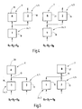
- FIG.1 is a schematic diagram of a total hydraulic power unit for operating a first consumer 6 and a second consumer 7 is shown.
- the hydraulic unit is formed of two partial units 1,2.
- a first partial unit 1 has a motor 2a, which has a first pressure medium pump 3 drives to promote from a pressure medium tank 12 (tank) pressure medium 9 and supply a pressure medium outlet 13.
- a second partial unit 2 is formed by a second motor 4, which drives a second pressure medium pump 5, the pressure medium 9, such as hydraulic oil, promotes from the pressure fluid reservoir 14 to a pressure medium outlet 15.
- the motors 2a, 4, preferably formed in the form of electric motors, have constant speeds.
- a pressure limiting valve 16,17 limits the pressure medium pressure at the pressure medium outlets 13,15.
- the first pressure medium pump 3 has a first delivery volume Q 1 , which is greater than the delivery volume Q 2 of the second pressure medium pump 5.
- the first consumer 6 is designed as a double-acting actuating cylinder 10.
- the second consumer 7 is also formed as a double-acting actuator cylinder 11.
- the first consumer 6 has a larger displacement than the second consumer 7. Due to the different size of the swallow volume, the two consumers should be able to move 6.7 different masses m A , m B , where m A > m B should be.
- a replacement circuit diagram 18 represents the first sub-assembly 1 and a replacement circuit diagram 19, the second sub-assembly 2.
- a replacement circuit diagram 20 represents the first consumer 6 and a replacement circuit diagram 21 the second consumer 7, wherein the information A, B to give an indication of the different sized, to be operated masses m A , m B.
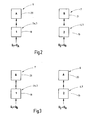
- Fig.2 is shown on the left side in the viewing direction, an energy-optimal operation of the first consumer 6 using basic replacement circuit diagrams.
- the first consumer 6 has the same operating volume as the first partial unit 1 and the delivery volume Q 1 of the first pressure medium pump 3 in the illustrated operating point.
- An energy-optimal operation of the second consumer 7 is shown on the right side.
- control unit 8 ensures, by the allocation of the various deliverable volume flows of pressure medium to the desired consumer 6,7, of which only two copies are shown, for the lowest possible energy loss of the entire arrangement of total hydraulic power unit and the consumers 6,7 or possibly other, not shown consumers. There are also other sub-aggregates in the overall hydraulic unit can be arranged if necessary.
- the second pressure medium pump 5 drives in the in Figure 4 illustrated modes of the entire hydraulic power unit to the second motor 4, whereby electrical energy is obtained.
- FIG. 5 3 shows a parallel operation of the two pressure medium pumps 3, 5 which jointly provide their respective delivery volumes Q 1 and Q 2 for operating the first or second consumers 6, 7 on the input side 13, 15 thereof. This results in each case a maximum possible actuating speed of the consumer 6,7 in terms of Q 1 + Q 2 > Q A concerning the consumer 6 and Q 1 + Q 2 >> Q B for the consumer. 7
- both partial units 1, 2 can be supplied from a common tank with filtered and cooled fluid.
- a cross or parallel connection and a series circuit is conceivable in which an increase in pressure takes place;
- an extension in the context of a feed station as a central energy source is possible.
Landscapes
- Engineering & Computer Science (AREA)
- Physics & Mathematics (AREA)
- Fluid Mechanics (AREA)
- Mechanical Engineering (AREA)
- General Engineering & Computer Science (AREA)
- Fluid-Pressure Circuits (AREA)
- Operation Control Of Excavators (AREA)
- Reciprocating Pumps (AREA)
Applications Claiming Priority (1)
| Application Number | Priority Date | Filing Date | Title |
|---|---|---|---|
| DE201010024025 DE102010024025A1 (de) | 2010-06-16 | 2010-06-16 | Hydraulikaggregat |
Publications (2)
| Publication Number | Publication Date |
|---|---|
| EP2397703A2 true EP2397703A2 (fr) | 2011-12-21 |
| EP2397703A3 EP2397703A3 (fr) | 2014-06-18 |
Family
ID=44675008
Family Applications (1)
| Application Number | Title | Priority Date | Filing Date |
|---|---|---|---|
| EP11004749.5A Withdrawn EP2397703A3 (fr) | 2010-06-16 | 2011-06-10 | Agrégat hydrophile |
Country Status (2)
| Country | Link |
|---|---|
| EP (1) | EP2397703A3 (fr) |
| DE (1) | DE102010024025A1 (fr) |
Citations (1)
| Publication number | Priority date | Publication date | Assignee | Title |
|---|---|---|---|---|
| JPH0483729U (fr) * | 1990-11-30 | 1992-07-21 |
Family Cites Families (6)
| Publication number | Priority date | Publication date | Assignee | Title |
|---|---|---|---|---|
| JPS57177407A (en) * | 1981-04-21 | 1982-11-01 | Toshiba Mach Co Ltd | Flow regulation valve and hydraulic control valve for injection molding machine employing said valve |
| DE59611324D1 (de) * | 1996-01-10 | 2006-04-06 | Eaton Fluid Power Gmbh | Verlustarmer Antrieb für einen hydraulischen Aktuator |
| DE19831828B4 (de) * | 1998-07-15 | 2008-05-08 | Linde Material Handling Gmbh | Hydrauliksystem für ein Flurförderzeug |
| DE10312417A1 (de) * | 2003-03-20 | 2004-09-30 | Henschel Recycling Technik Gmbh | Hydraulikaggregat, insbesondere für Schrottscheren ud Schrottpressen |
| US7559197B2 (en) * | 2005-08-31 | 2009-07-14 | Caterpillar Inc. | Combiner valve control system and method |
| EP2022990B1 (fr) * | 2007-08-07 | 2016-10-12 | HAWE Hydraulik SE | Machine outil et unité d'alimentation |
-
2010
- 2010-06-16 DE DE201010024025 patent/DE102010024025A1/de not_active Withdrawn
-
2011
- 2011-06-10 EP EP11004749.5A patent/EP2397703A3/fr not_active Withdrawn
Patent Citations (1)
| Publication number | Priority date | Publication date | Assignee | Title |
|---|---|---|---|---|
| JPH0483729U (fr) * | 1990-11-30 | 1992-07-21 |
Also Published As
| Publication number | Publication date |
|---|---|
| EP2397703A3 (fr) | 2014-06-18 |
| DE102010024025A1 (de) | 2011-12-22 |
Similar Documents
| Publication | Publication Date | Title |
|---|---|---|
| EP2503160B1 (fr) | Système d'entraînement hydraulique | |
| DE102015007479B4 (de) | Aktive aufhängungsvorrichtung für ein fahrzeug | |
| EP2676036B1 (fr) | Système d'entraînement hydraulique sans accumulateur de pression pour un consommateur et comprenant un consommateur, en particulier pour des presses, et procédé permettant de faire fonctionner un tel système d'entraînement hydraulique sans accumulateur de pression | |
| EP2024140B1 (fr) | Pompe à lubrifiant automatique avec piston d'entraînement à double action | |
| DE102006060351B3 (de) | Hydraulische Schaltungsanordnung mit Energierückgewinnung | |
| DE102015007460B4 (de) | Aktive aufhängungsvorrichtung für ein fahrzeug und eine dafür verwendete pumpe | |
| WO2015185644A1 (fr) | Système hydraulique | |
| DE102014213264A1 (de) | Hydraulische Anordnung zur Versorgung eines Verbrauchers | |
| EP2846942B1 (fr) | Presse à filer hydraulique et procédé de fonctionnement d'une presse à filer hydraulique | |
| WO2006102948A1 (fr) | Pompe hydraulique pour véhicule à moteur | |
| DE102006058802A1 (de) | Hydrostatischer Mehrmotorenatrieb | |
| AT518192B1 (de) | Hydraulikvorrichtung für eine Formgebungsmaschine | |
| DE102016011900A1 (de) | Hydraulische Antriebsvorrichtung für eine Formgebungsmaschine | |
| DE102010024246A1 (de) | Verfahren und Vorrichtung zum Betrieb einer angetriebenen Achse bei einer Werkzeugmaschine | |
| DE102009025707B4 (de) | Vorrichtung zur Steuerung einer Anlage mit Hydraulikkreisen | |
| EP2397703A2 (fr) | Agrégat hydrophile | |
| EP2280197A1 (fr) | Entraînement hydrostatique de plusieurs moteurs | |
| AT524891B1 (de) | Hydraulische Antriebsvorrichtung für eine Formgebungsmaschine | |
| DE102021212305A1 (de) | Elektronische Steuereinheit für einen hydraulischen Antrieb, hydraulischer Antrieb und Verfahren mit einem hydraulischen Antrieb | |
| DE102008002386A1 (de) | Antriebsstrang für ein Kraftfahrzeug und Verfahren zum Betreiben des Antriebsstrangs | |
| EP0771639A2 (fr) | Entraînement hybride hydraulique et électrique d'une machine de moulage avec un convertisseur de fréquence commun | |
| AT519817B1 (de) | Hydrauliksystem | |
| AT525047B1 (de) | Hydraulische Antriebsvorrichtung für eine Formgebungsmaschine | |
| EP0952354B1 (fr) | Circuit pour le mouvement rapide des moteurs et des cylindres hydrauliques | |
| EP4190978A1 (fr) | Dispositif d'entraînement d'une machine de travail mobile, en particulier électrique |
Legal Events
| Date | Code | Title | Description |
|---|---|---|---|
| AK | Designated contracting states |
Kind code of ref document: A2 Designated state(s): AL AT BE BG CH CY CZ DE DK EE ES FI FR GB GR HR HU IE IS IT LI LT LU LV MC MK MT NL NO PL PT RO RS SE SI SK SM TR |
|
| AX | Request for extension of the european patent |
Extension state: BA ME |
|
| PUAI | Public reference made under article 153(3) epc to a published international application that has entered the european phase |
Free format text: ORIGINAL CODE: 0009012 |
|
| PUAL | Search report despatched |
Free format text: ORIGINAL CODE: 0009013 |
|
| AK | Designated contracting states |
Kind code of ref document: A3 Designated state(s): AL AT BE BG CH CY CZ DE DK EE ES FI FR GB GR HR HU IE IS IT LI LT LU LV MC MK MT NL NO PL PT RO RS SE SI SK SM TR |
|
| AX | Request for extension of the european patent |
Extension state: BA ME |
|
| RIC1 | Information provided on ipc code assigned before grant |
Ipc: F15B 15/26 20060101AFI20140515BHEP |
|
| 17P | Request for examination filed |
Effective date: 20140708 |
|
| STAA | Information on the status of an ep patent application or granted ep patent |
Free format text: STATUS: EXAMINATION IS IN PROGRESS |
|
| 17Q | First examination report despatched |
Effective date: 20171113 |
|
| STAA | Information on the status of an ep patent application or granted ep patent |
Free format text: STATUS: THE APPLICATION IS DEEMED TO BE WITHDRAWN |
|
| 18D | Application deemed to be withdrawn |
Effective date: 20210907 |