EP2397775A2 - Dispositif d'aspiration - Google Patents
Dispositif d'aspiration Download PDFInfo
- Publication number
- EP2397775A2 EP2397775A2 EP11004914A EP11004914A EP2397775A2 EP 2397775 A2 EP2397775 A2 EP 2397775A2 EP 11004914 A EP11004914 A EP 11004914A EP 11004914 A EP11004914 A EP 11004914A EP 2397775 A2 EP2397775 A2 EP 2397775A2
- Authority
- EP
- European Patent Office
- Prior art keywords
- hob
- suction
- flow path
- air flow
- deduction device
- Prior art date
- Legal status (The legal status is an assumption and is not a legal conclusion. Google has not performed a legal analysis and makes no representation as to the accuracy of the status listed.)
- Withdrawn
Links
Images


Classifications
-
- F—MECHANICAL ENGINEERING; LIGHTING; HEATING; WEAPONS; BLASTING
- F24—HEATING; RANGES; VENTILATING
- F24C—DOMESTIC STOVES OR RANGES ; DETAILS OF DOMESTIC STOVES OR RANGES, OF GENERAL APPLICATION
- F24C15/00—Details
- F24C15/20—Removing cooking fumes
- F24C15/2042—Devices for removing cooking fumes structurally associated with a cooking range e.g. downdraft
-
- F—MECHANICAL ENGINEERING; LIGHTING; HEATING; WEAPONS; BLASTING
- F24—HEATING; RANGES; VENTILATING
- F24C—DOMESTIC STOVES OR RANGES ; DETAILS OF DOMESTIC STOVES OR RANGES, OF GENERAL APPLICATION
- F24C15/00—Details
- F24C15/10—Tops, e.g. hot plates; Rings
- F24C15/102—Tops, e.g. hot plates; Rings electrically heated
- F24C15/103—Tops, e.g. hot plates; Rings electrically heated being movable or rotatable
Definitions
- the invention relates to a trigger device for removing vapors, stews or the like from a hob according to the preamble of claim 1.
- the present invention has the object to increase the effectiveness of such a take-off device.
- the effectiveness of a take-off device is determined inter alia, which suction is possible. In addition to the performance of the suction fan, this also depends on the air resistance, which counteract suction. These can be reduced by an enlargement of the cross-section of the lines, but above all, the air resistance of the filter elements has a decisive influence.
- the filter elements are now arranged over a large area under the hob, so that on the one hand a good filtering effect is achieved, on the other hand, however, the air resistance is reduced.
- the arrangement of the filter elements with a large cross-sectional area under the hob can be facilitated by the fact that the hob can be flipped up to change the filter and clean or to maintain and clean the air flow path or the housing of the trigger.
- the large filter area thus significantly reduces the backpressure conditions and thus the air resistance.
- the filter elements are preferably arranged diagonally in the air flow path and mirror-symmetrically in order to achieve this large air passage area.
- the suction openings are covered by closable flaps, so that a reliable cover is ensured in the idle state.
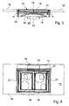
- the figures show a take-off device, as used in particular for removing fumes, stews or the like in private kitchens or in commercial workplaces via stoves or cooking zones.
- the exhaust device has filter elements 16 and is connected via an air flow path 20, which is formed by air ducts, to a drawing not shown suction fan.
- the air ducts are in the embodiment by the side suction ducts 11, the rear suction duct 14, the collection duct 17 and formed the common suction.
- the suction shafts 11, 14 are arranged along the hob 10, which is embedded in the embodiment in a countertop 18, and have along the hob extending elongated suction openings 12, 15, which are closed with flaps 21. In the operating state, the flaps 21 open and release the suction openings 12, 15 of the suction shafts 11, 14.
- the extraction chutes are arranged both laterally and behind the hob 10, with several cooktops can also optionally be provided between the cooktops forming cooking hobs extraction ducts.
- the suction openings 12, 15 preferably surround the hob 10 fluidically at least three sides, so that the fumes and vapors can be sucked reliable and efficient.
- the windrows are received in a complete frame / channel system that lays individually around the hob 10.
- a corresponding suction duct can also be arranged between the hob cooking modules.
- the dimensions of the extraction ducts depend on the hobs used, i. their width, depth and edge profile and can be set individually.
- the filter elements 16 are preferably arranged as removable cassettes under the hob 10.
- the hob can from a position lm operating state according to Fig. 1 in a position according to Fig. 2 be unfolded.
- a folding mechanism 19 is provided, which also has a fixation of the hob at least in its end position, preferably in its respective position.
- the filter elements 16 are arranged diagonally in the air flow path 20, which increases the cross-sectional area of the filter elements 16 to be flowed through and at the same time reduces the air resistance formed by the filter elements 16, so that the suction power is increased.
- an approximately 20% increased suction with otherwise unchanged boundary conditions and the same filter effect has been found in comparison to an arrangement of the filter elements directly to the suction. This is especially important in a cooktop extractor device important because the vapors should not rise as possible, but should be detected directly by the trigger.
- the filter elements 16 are arranged mirror-symmetrically to a center line of the hob 10.
- the suction openings 12,15 are closed by movable and / or movable flaps 21.
- the suction ducts 11, 14 with the hob 10 can be folded out, if necessary, only the hob can be easily accessible of filter elements and extraction device is ensured under the hob 10.
- the underside of the deployable hob 10 in the operating state form at least part of the air flow path 20 by the bottom limits the air flow path 20 upwards.
- the Ausklappbarkeft the system is very easy to clean.
- the system can be provided independently of the manufacturer of the hob and regardless of the dimensions of the hob, as long as it is ensured that extracted air can reach the filter elements 16 via the suction openings.
Landscapes
- Engineering & Computer Science (AREA)
- Chemical & Material Sciences (AREA)
- Combustion & Propulsion (AREA)
- Mechanical Engineering (AREA)
- General Engineering & Computer Science (AREA)
- Ventilation (AREA)
- Filtering Of Dispersed Particles In Gases (AREA)
- Machine Tool Units (AREA)
- Cleaning In General (AREA)
Applications Claiming Priority (2)
| Application Number | Priority Date | Filing Date | Title |
|---|---|---|---|
| DE201020009195 DE202010009195U1 (de) | 2010-06-17 | 2010-06-17 | Abzugsvorrichtung |
| DE102011008428A DE102011008428A1 (de) | 2010-06-17 | 2011-01-12 | Abzugsvorrichtung |
Publications (2)
| Publication Number | Publication Date |
|---|---|
| EP2397775A2 true EP2397775A2 (fr) | 2011-12-21 |
| EP2397775A3 EP2397775A3 (fr) | 2012-08-15 |
Family
ID=44862219
Family Applications (1)
| Application Number | Title | Priority Date | Filing Date |
|---|---|---|---|
| EP11004914A Withdrawn EP2397775A3 (fr) | 2010-06-17 | 2011-06-16 | Dispositif d'aspiration |
Country Status (2)
| Country | Link |
|---|---|
| EP (1) | EP2397775A3 (fr) |
| DE (1) | DE102011008428A1 (fr) |
Cited By (10)
| Publication number | Priority date | Publication date | Assignee | Title |
|---|---|---|---|---|
| WO2014089419A1 (fr) * | 2012-12-06 | 2014-06-12 | Electrolux Home Products, Inc. | Plan de cuisson à induction à abattant |
| EP2899470A3 (fr) * | 2014-01-15 | 2016-01-06 | Wesco Ag | Hotte aspirante |
| EP3382285A1 (fr) * | 2017-03-29 | 2018-10-03 | Baraldi Srl | Système d'ouverture avec ressorts à pression à gaz et charnières pour table de cuisson à induction avec hotte intégrée |
| WO2019197055A1 (fr) * | 2018-04-10 | 2019-10-17 | BSH Hausgeräte GmbH | Dispositif de filtrage et dispositif d'évacuation de fumée comprenant un dispositif de filtrage |
| IT201800006807A1 (it) * | 2018-06-29 | 2019-12-29 | Gruppo piano cottura e cappa. | |
| IT201900012393A1 (it) * | 2019-07-19 | 2021-01-19 | Meneghetti S P A Unipersonale | Apparecchio di cottura |
| CN113048524A (zh) * | 2019-12-26 | 2021-06-29 | 广东合捷电器股份有限公司 | 厨房电器 |
| CN113048525A (zh) * | 2019-12-26 | 2021-06-29 | 广东合捷电器股份有限公司 | 空气净化模块和厨房电器 |
| EP3631303B1 (fr) * | 2017-05-29 | 2021-08-04 | Wilhelm Bruckbauer | Système à table de cuisson |
| IT202300021561A1 (it) * | 2023-10-17 | 2025-04-17 | Baraldi S R L | Piano cottura ad induzione, piano di lavoro per cucina e metodo di realizzazione del piano di lavoro per cucina |
Families Citing this family (3)
| Publication number | Priority date | Publication date | Assignee | Title |
|---|---|---|---|---|
| DE102015104470B4 (de) * | 2015-03-25 | 2021-06-02 | Miele & Cie. Kg | Kochfeld sowie ein Verfahren zum Betreiben eines Kochfeldes |
| DE102016112252A1 (de) * | 2016-07-05 | 2018-01-11 | Daniel Braun | Dunstabzug |
| DE102017209001A1 (de) | 2017-05-29 | 2018-11-29 | Wilhelm Bruckbauer | Kochfeld-Vorrichtung |
Family Cites Families (10)
| Publication number | Priority date | Publication date | Assignee | Title |
|---|---|---|---|---|
| AT371911B (de) * | 1981-07-22 | 1983-08-10 | Matrei Geraetewerk | Kochfeld |
| DE3601460A1 (de) | 1986-01-20 | 1987-07-23 | Gaggenau Werke | Vorrichtung zum abzug der wrasen an kuechengeraeten |
| DE4321530A1 (de) * | 1993-06-29 | 1995-01-12 | Kueppersbusch | Luftführungsgerät |
| US5671726A (en) * | 1995-06-20 | 1997-09-30 | Hsu; Robert Y. | Cooking fume purifier |
| DE19532707C2 (de) * | 1995-09-05 | 1998-04-09 | Mayer Gmbh Geb | Kochfeld für eine Haushaltsküche |
| DE19747570A1 (de) * | 1996-11-05 | 1998-05-07 | Bosch Siemens Hausgeraete | Dunstabzugshaube zum bestimmungsgemäßen Einsatz über ein Kochfeld |
| US6455818B1 (en) * | 2001-08-23 | 2002-09-24 | Maytag Corporation | Downdraft filter assembly for a cooking appliance |
| DE102005030038B4 (de) * | 2005-06-27 | 2021-11-25 | Wilhelm Bruckbauer | Kochfeldabzugsvorrichtung |
| DE102006039087B4 (de) * | 2006-08-19 | 2009-09-03 | Electrolux Home Products N.V. | Gargerät, insbesondere Haushalts-Gargerät |
| DE202007000610U1 (de) * | 2007-01-10 | 2007-04-12 | Bruckbauer Wilhelm | Vorrichtung zum Abzug von Kochdünsten |
-
2011
- 2011-01-12 DE DE102011008428A patent/DE102011008428A1/de not_active Withdrawn
- 2011-06-16 EP EP11004914A patent/EP2397775A3/fr not_active Withdrawn
Cited By (13)
| Publication number | Priority date | Publication date | Assignee | Title |
|---|---|---|---|---|
| WO2014089419A1 (fr) * | 2012-12-06 | 2014-06-12 | Electrolux Home Products, Inc. | Plan de cuisson à induction à abattant |
| EP2899470A3 (fr) * | 2014-01-15 | 2016-01-06 | Wesco Ag | Hotte aspirante |
| EP3382285A1 (fr) * | 2017-03-29 | 2018-10-03 | Baraldi Srl | Système d'ouverture avec ressorts à pression à gaz et charnières pour table de cuisson à induction avec hotte intégrée |
| EP3631303B1 (fr) * | 2017-05-29 | 2021-08-04 | Wilhelm Bruckbauer | Système à table de cuisson |
| WO2019197055A1 (fr) * | 2018-04-10 | 2019-10-17 | BSH Hausgeräte GmbH | Dispositif de filtrage et dispositif d'évacuation de fumée comprenant un dispositif de filtrage |
| US11885505B2 (en) | 2018-04-10 | 2024-01-30 | BSH Hausgeräte GmbH | Filter device and fume extraction device comprising filter device |
| WO2020002456A1 (fr) * | 2018-06-29 | 2020-01-02 | B.S. Service S.R.L. | Ensemble plaque de cuisson-hotte aspirante |
| IT201800006807A1 (it) * | 2018-06-29 | 2019-12-29 | Gruppo piano cottura e cappa. | |
| IT201900012393A1 (it) * | 2019-07-19 | 2021-01-19 | Meneghetti S P A Unipersonale | Apparecchio di cottura |
| CN113048524A (zh) * | 2019-12-26 | 2021-06-29 | 广东合捷电器股份有限公司 | 厨房电器 |
| CN113048525A (zh) * | 2019-12-26 | 2021-06-29 | 广东合捷电器股份有限公司 | 空气净化模块和厨房电器 |
| IT202300021561A1 (it) * | 2023-10-17 | 2025-04-17 | Baraldi S R L | Piano cottura ad induzione, piano di lavoro per cucina e metodo di realizzazione del piano di lavoro per cucina |
| EP4542120A1 (fr) * | 2023-10-17 | 2025-04-23 | Baraldi S.r.l. | Plan de travail pour une cuisine et procédé de fabrication du plan de travail pour cuisine |
Also Published As
| Publication number | Publication date |
|---|---|
| DE102011008428A1 (de) | 2011-12-22 |
| EP2397775A3 (fr) | 2012-08-15 |
Similar Documents
| Publication | Publication Date | Title |
|---|---|---|
| EP2397775A2 (fr) | Dispositif d'aspiration | |
| EP1194721B1 (fr) | Dispositif d'aspiration d'air pour poste de travail | |
| EP3338031B1 (fr) | Appareil combiné avec plaque de cuisson et dispositif d'evacuation des fumées | |
| EP3701192B1 (fr) | Appareil combiné comprenant un dispositif d'aspiration de fumées et une plaque de cuisson | |
| EP3475622B1 (fr) | Système de ventilation à courant descendant avec un insert | |
| EP3136004B1 (fr) | Appareil combiné comprenant une plaque de cuisson et un dispositif d'aspiration de fumées | |
| EP3045824B1 (fr) | Dispositif d'aspiration d'air d'une cuisiniere | |
| DE102017216456A1 (de) | Lüftungsvorrichtung für Kochfeld und Kochfeld mit Lüftungsvorrichtung | |
| EP3338029A1 (fr) | Appareil combiné comprenant une plaque de cuisson et un dispositif d'aspiration des émanations | |
| EP2210048B1 (fr) | Dispositif d'aspiration de vapeurs | |
| DE102020104387B4 (de) | Kochfeld mit Kochstelle und Absaugvorrichtung für Kochdünste | |
| EP3598006B1 (fr) | Hotte aspirante pour une plaque de cuisson intégrée dans un meuble, procédé de fonctionnement de la hotte aspirante et meuble doté d'une plaque de cuisson et d'une hotte aspirante | |
| EP1696180A2 (fr) | Dispositif d'aspiration pour un système de cuisson, en particulier une plaque de cuisson ou équivalent | |
| EP3722676A1 (fr) | Dispositif ventilateur permettant d'aspirer et d'évacuer des vapeurs en dessous d'une plaque de cuisson, procédé de fonctionnement du dispositif ventilateur et plaque de cuisson | |
| EP2829808B1 (fr) | Hotte aspirante | |
| DE202012104696U1 (de) | Dunstabzugshaube | |
| DE202023102435U1 (de) | Abluftvorrichtung und Kocheinrichtung mit derselben | |
| DE19950817A1 (de) | Dunstabzugsvorrichtung | |
| DE10008014A1 (de) | Dunstabzugshaube | |
| DE102018130963A1 (de) | Dunstabzugseinrichtung für eine Schrank- oder Küchenzeile | |
| DE102018119698A1 (de) | Dunstabzugssystem für Kochfelder | |
| DE10064328A1 (de) | Dunstabzugshaube | |
| EP2397776A2 (fr) | Dispositif d'aspiration | |
| DE102015100745A1 (de) | Absaugvorrichtung und Verfahren zum Betreiben | |
| DE102022131774B4 (de) | Dunstabzugseinrichtung |
Legal Events
| Date | Code | Title | Description |
|---|---|---|---|
| AK | Designated contracting states |
Kind code of ref document: A2 Designated state(s): AL AT BE BG CH CY CZ DE DK EE ES FI FR GB GR HR HU IE IS IT LI LT LU LV MC MK MT NL NO PL PT RO RS SE SI SK SM TR |
|
| AX | Request for extension of the european patent |
Extension state: BA ME |
|
| PUAI | Public reference made under article 153(3) epc to a published international application that has entered the european phase |
Free format text: ORIGINAL CODE: 0009012 |
|
| PUAL | Search report despatched |
Free format text: ORIGINAL CODE: 0009013 |
|
| AK | Designated contracting states |
Kind code of ref document: A3 Designated state(s): AL AT BE BG CH CY CZ DE DK EE ES FI FR GB GR HR HU IE IS IT LI LT LU LV MC MK MT NL NO PL PT RO RS SE SI SK SM TR |
|
| AX | Request for extension of the european patent |
Extension state: BA ME |
|
| RIC1 | Information provided on ipc code assigned before grant |
Ipc: F24C 15/20 20060101AFI20120712BHEP Ipc: F24C 15/10 20060101ALI20120712BHEP |
|
| STAA | Information on the status of an ep patent application or granted ep patent |
Free format text: STATUS: THE APPLICATION IS DEEMED TO BE WITHDRAWN |
|
| 18D | Application deemed to be withdrawn |
Effective date: 20130216 |