EP2398033A2 - Bewegliche Dichtung mit Lichtbogenkriechstromoberfläche für einen Druckluftschalter - Google Patents
Bewegliche Dichtung mit Lichtbogenkriechstromoberfläche für einen Druckluftschalter Download PDFInfo
- Publication number
- EP2398033A2 EP2398033A2 EP11004896A EP11004896A EP2398033A2 EP 2398033 A2 EP2398033 A2 EP 2398033A2 EP 11004896 A EP11004896 A EP 11004896A EP 11004896 A EP11004896 A EP 11004896A EP 2398033 A2 EP2398033 A2 EP 2398033A2
- Authority
- EP
- European Patent Office
- Prior art keywords
- arc
- circuit breaker
- contact
- moving seal
- creepage surface
- Prior art date
- Legal status (The legal status is an assumption and is not a legal conclusion. Google has not performed a legal analysis and makes no representation as to the accuracy of the status listed.)
- Withdrawn
Links
- 230000000712 assembly Effects 0.000 claims abstract description 18
- 238000000429 assembly Methods 0.000 claims abstract description 18
- 238000007789 sealing Methods 0.000 claims description 18
- 239000007789 gas Substances 0.000 description 5
- 239000004020 conductor Substances 0.000 description 4
- 238000000926 separation method Methods 0.000 description 3
- 238000000034 method Methods 0.000 description 1
- 230000001012 protector Effects 0.000 description 1
- 239000011435 rock Substances 0.000 description 1
Images



Classifications
-
- H—ELECTRICITY
- H01—ELECTRIC ELEMENTS
- H01H—ELECTRIC SWITCHES; RELAYS; SELECTORS; EMERGENCY PROTECTIVE DEVICES
- H01H73/00—Protective overload circuit-breaking switches in which excess current opens the contacts by automatic release of mechanical energy stored by previous operation of a hand reset mechanism
- H01H73/02—Details
- H01H73/18—Means for extinguishing or suppressing arc
-
- H—ELECTRICITY
- H01—ELECTRIC ELEMENTS
- H01H—ELECTRIC SWITCHES; RELAYS; SELECTORS; EMERGENCY PROTECTIVE DEVICES
- H01H9/00—Details of switching devices, not covered by groups H01H1/00 - H01H7/00
- H01H9/30—Means for extinguishing or preventing arc between current-carrying parts
- H01H9/32—Insulating body insertable between contacts
-
- H—ELECTRICITY
- H01—ELECTRIC ELEMENTS
- H01H—ELECTRIC SWITCHES; RELAYS; SELECTORS; EMERGENCY PROTECTIVE DEVICES
- H01H1/00—Contacts
- H01H1/12—Contacts characterised by the manner in which co-operating contacts engage
- H01H1/14—Contacts characterised by the manner in which co-operating contacts engage by abutting
- H01H1/22—Contacts characterised by the manner in which co-operating contacts engage by abutting with rigid pivoted member carrying the moving contact
- H01H1/221—Contacts characterised by the manner in which co-operating contacts engage by abutting with rigid pivoted member carrying the moving contact and a contact pressure spring acting between the pivoted member and a supporting member
- H01H1/226—Contacts characterised by the manner in which co-operating contacts engage by abutting with rigid pivoted member carrying the moving contact and a contact pressure spring acting between the pivoted member and a supporting member having a plurality of parallel contact bars
-
- H—ELECTRICITY
- H01—ELECTRIC ELEMENTS
- H01H—ELECTRIC SWITCHES; RELAYS; SELECTORS; EMERGENCY PROTECTIVE DEVICES
- H01H9/00—Details of switching devices, not covered by groups H01H1/00 - H01H7/00
- H01H9/30—Means for extinguishing or preventing arc between current-carrying parts
- H01H2009/305—Means for extinguishing or preventing arc between current-carrying parts including means for screening for arc gases as protection of mechanism against hot arc gases or for keeping arc gases in the arc chamber
-
- H—ELECTRICITY
- H01—ELECTRIC ELEMENTS
- H01H—ELECTRIC SWITCHES; RELAYS; SELECTORS; EMERGENCY PROTECTIVE DEVICES
- H01H50/00—Details of electromagnetic relays
- H01H50/02—Bases; Casings; Covers
- H01H2050/028—Means to improve the overall withstanding voltage, e.g. creepage distances
Definitions
- a common type of circuit breaker is the air circuit breaker, which uses a flow of gas to extinguish the arc caused by separation of the contacts.
- the flow of gas may be provided by a source of compressed gas or by air exiting a sealed arc chamber that is pressurized when the contacts separate.
- the pressurization of the arc chamber may be accomplished by a moving seal that acts in cooperation with a contact carriage that carries the moveable contact away from the stationary contact.
- the moving seal moves into the arc chamber when the contacts separate, displacing air in the arc chamber.
- the air flows out of the arc chamber through an arc chute and extinguishes the arc.
- the moving seal is typically positioned near the stationary contact so that it can properly extinguish the arc. However, this close proximity may allow the arc to creep up the moving seal and short to the contact carriage, causing a short circuit condition.
- a moving seal for an air circuit breaker includes a sealing portion having an arc creepage surface that is positioned between first and second circuit breaker contacts when the sealing portion is fit into an inlet of an arc chamber enclosing the first and second circuit breaker contacts.
- the arc creepage surface has a surface contour that increases the length of an arc travel path between the second circuit breaker contact and a contact carriage that carries the first circuit breaker contact, relative to a straight line distance between the second circuit breaker contact and the contact carriage.
- the arc creepage surface may have a substantially concave surface contour that includes a single concave groove or a plurality of parallel concave grooves.
- the moving seal also includes an actuation portion configured to co-act with the contact carriage, where the contact carriage is operable to separate the first and second circuit breaker contacts.
- the arc chamber is substantially closed and the inlet is formed between the first and second circuit breaker contacts when the contact carriage carries the first circuit breaker contact away from the second circuit breaker contact.
- the sealing portion of the moving seal is configured to fit within the inlet open to seal the inlet and define a portion of the arc chamber.
- the actuation portion is operable to selectively position the sealing portion in the inlet when the contact carriage carries the first circuit breaker contact away from the second circuit breaker contact.
- an air circuit breaker in another embodiment, includes a substantially closed arc chamber enclosing a pair of separable contact assemblies.
- the arc chamber includes an inlet that is formed between the pair of separable contact assemblies when the separable contact assemblies are separated.
- the air circuit breaker includes a moving seal configured to be fit within the inlet to close the inlet and define a portion of the arc chamber.
- the moving seal includes an arc creepage surface that is positioned between the pair of separable contact assemblies when the moving seal is fit into the inlet.
- the arc creepage surface has a surface contour that increases the length of an arc travel path between the pair of separable contact assemblies, relative to a straight line distance between the pair of separable contact assemblies.
- the arc creepage surface may have a substantially concave surface contour that includes a single concave groove or a plurality of parallel concave grooves.
- Figure 1 illustrates a prior art three pole air circuit breaker with a moving seal.
- Figure 1A is a perspective view of the moving seal in the air circuit breaker shown in Figure 1 .
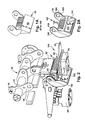
- Figure 2 is a perspective view of a single circuit breaker pole that includes an example embodiment of a moving seal with an arc creepage surface.
- Figure 2A is a perspective view of the moving seal with arc creepage surface in the pole shown in Figure 2 .
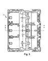
- Figure 3 is a front view of a three pole air circuit breaker that includes the pole shown in Figure 2 and that indicates a cross section to be shown in Figures 4-6 .
- Figure 4 is a cross section of the air circuit breaker taken along 4-4 as indicated in Figure 3 with a pole assembly in a closed or conducting position.
- Figure 5 is a cross section of the air circuit breaker taken along 4-4 as indicated in Figure 3 with a pole assembly in an intermediate contact separation position.
- Figure 6 is a cross section of the air circuit breaker taken along 4-4 as indicated in Figure 3 with a pole assembly in an open or non-conducting position.
- Figure 7 is a perspective view of another example embodiment of a moving seal that includes an arc creepage surface.
- FIG. 1 A prior art air circuit breaker 1 is illustrated in Figure 1 .
- the air circuit breaker includes a housing 3 (shown in dashed line) that forms three pole chambers 4 ,5 ,6, each configured to house a circuit breaker pole 10 (only one pole 10 is shown in solid line in Figure 1 ).
- An operating mechanism 15 is mounted to a front end of the housing 3.
- the operating mechanism 15 is common to all three circuit breaker poles 10 and is connected to the individual poles by a pole shaft 33 that has a lobe 35 for each pole.
- the operating mechanism 15 includes a trip unit (not shown) that actuates the operating mechanism to open all the poles of the circuit breaker through rotation of the pole shaft 33 in response to predetermined characteristics of the current flowing through the circuit breaker.
- the operating mechanism 15 may be manually actuated by way of a switch lobe portion 36.
- the switch lobe portion 36 is connected to one or more manually operable switches (not shown) that are accessible outside the housing 3.
- the pole 10 which will be described in more detail below, includes a stationary contact assembly 25 configured to be connected to a line conductor (not shown) that projects rearwardly from the housing 3.
- the pole 10 also includes a movable contact assembly 45 that is mounted to a contact carriage 40.
- the contact carriage 40 is operable to carry the moveable contact assembly 45 away from the stationary contact assembly 25.
- the moveable contact assembly 45 includes a plurality of contact fingers 47 that are pivotally mounted to the contact carriage 40.
- the moveable contact assembly 45 provides a current path between the stationary contact assembly 25 and a load conductor connector assembly 65 configured to be connected to a load conductor (not shown).
- the current path includes a stationary contact 27, a moveable contact 42 and a flexible shunt (not shown) connected to bottom end 49 shunt connection feature ( Figure 4 ) of the contact fingers 47.
- a moving seal 50 is also pivotally mounted to the moveable contact carriage 40.
- the moving seal 50 includes a sealing surface 52 that forms one portion of a sealed arc chamber (not visible in Figure 1 ).
- the moving seal 50 rotates toward the stationary contact assembly 25 and is positioned between the contact carriage 40 and the stationary contact 27 when the contact carriage 40 separates the contacts to pressurize the arc chamber and extinguish the arc.
- the sealing surface 52 is substantially planar and presents a straight line path for the arc to travel when the contacts are separated. This may cause the moving seal 50 to be susceptible to shorting due to arc creepage as discussed in the background section. This is because the planar sealing surface 52 provides a relatively short straight line path, labeled "D", between the contact carriage 40 and the stationary contact 27 during contact separation.
- FIG 2 illustrates a circuit breaker pole 110 that includes many of the same components as the pole 10 shown in Figure 1 and which are assigned the same reference numeral as in Figure 1 .
- the contact carriage 40' includes a moving seal 150 that has an arc creepage surface 152.
- the arc creepage surface 152 is generally concave when compared to the generally planar sealing surface 52 of the moving seal 50 shown in Figure 1 .
- the arc creepage surface 152 is configured to increase the distance (“D"'), relative to the distance presented by the planar sealing surface 52, that the arc must travel along the arc creepage surface 152 before shorting to the contact carriage 40' while still providing an adequate amount of pressurization of the arc chamber to extinguish the arc.
- a generally concave arc creepage surface 152 is shown in Figure 2 , however, it will be appreciated that the arc creepage surface could be embodied in any configuration that increases the distance, relative to the straight line distance D presented by the planar sealing surface 52, that the arc must travel along the moving seal 150 before shorting to the contact carriage 40'.
- FIG 2A illustrates the moving seal 150 in more detail.
- the moving seal 150 includes a sealing portion 151 and an actuation portion 153.
- the sealing portion includes the arc creepage surface 152 as well as fins 199 that extend behind the arc creepage surface 152.
- the sealing portion 151 is configured to be positioned between the stationary contact 27 ( Figure 2 ) and the contact carriage 40' ( Figure 2 ) when the contact carriage moves the moveable contact 42 away from the stationary contact 27.
- the arc creepage surface 152 defines a portion of the arc chamber when the arc is being extinguished ( Figure 5 ).
- the actuation portion 153 includes spaced legs 195 that have circular recesses 185 that engage the ends of a pivot pin 51 ( Figure 4 ) to secure the moving seal 150 to the contact carriage 40' as seen in Figure 2 .
- the pivot pin 51 is also used to pivotally mount the contact fingers 27 to the contact carriage 40'.
- the moving seal 150 by way of the actuation portion, co-acts with the contact carriage 40' to position the moving seal 150 between the contact carriage and the stationary contact 27 when the contacts separate.
- the fins 199 on the moving seal 150 extend between the contact fingers 47 and align with fins (not shown) arranged between the contact fingers on the contact carriage 40' to form a seal which prevents the flow of arc gases from passing through the spaces between the contact fingers.
- Figures 3 is a front view of an air circuit breaker 1 that houses three poles 110 shown in Figure 2 .
- Section 4-4 is indicated in Figure 3 and will be used for the cross section views of a pole 110 shown in Figures 4-6 .
- the pole 110 can be seen positioned within an arc chamber 13.
- the arc chamber which is substantially closed to so that it can be pressurized, includes an outlet 18 through which arc gases may pass.
- the pole 110 is in a closed position so that current may be conducted from the stationary contact assembly 25 to the load connector assembly 65.
- the contact fingers 47 on the moveable contact assembly 45 are positioned so that the moveable contacts 42 abut the stationary contacts 27. Springs 74 urge the contact fingers 47 into the closed position.
- the moveable contacts 42 are fixed to the contact fingers 47 about midway between the pivot pin 51 and a first or free end 41.
- a shunt connection feature 49 on the contact fingers 47 is adapted to be connected to a flexible shunt (not shown) that connects the contact fingers 47 to the load conductor connector assembly 65.
- Adjacent to the free end 41 of the contact fingers is an arc toe 43 that forms a moveable arcing contact which cooperates with an arc runner 35 to guide the arc from into an arc chute 17 in the arc chamber 13 to be extinguished.
- the moving seal 150 is also pivotally mounted to the pivot pin 51 on the contact carriage 40'. In the closed position, the moving seal 150 is positioned down below the stationary contact 27.
- Figure 5 illustrates the circuit breaker pole 110 as it begins to open in response to rotation of the shaft 33 that acts upon the linkage between the lobe 35 and link 37 to rotate the contact carriage 40'.
- An arc chamber inlet 16 is created by the movement of the contact carriage 40'.
- the contact carriage 40' begins to rotate counter clockwise and the springs 74 rock the contact fingers 47 clockwise so that arc toe 43 contacts the arc runner while the moveable contacts 42 are separated from the stationary contact 27.
- Continued rotation of the contact carriage causes the moving seal 150 rotate up toward the stationary contacts 27 to the position shown in Figure 5 .
- the moving seal 150 is positioned to seal between the contact fingers 47 and to place the arc creepage surface 152 just below the stationary contact 27 to close off the arc chamber inlet 16 so that the arc can be extinguished.
- FIG. 6 shows the pole 110 in the open position.
- the contact carriage 40' has rotated counterclockwise until it rests against a stop 165 in the housing.
- the moveable contacts 42 are separated from the stationary contact 27 and the arc toe is also separated from the arc runner 35.
- Figure 7 illustrates an alternative embodiment of a moving seal 250 with an arc creepage surface 252 that includes a plurality of parallel concave grooves 255.
- the grooved arc creepage surface 252 increases the distance, relative to the distance D presented by the planar sealing surface 52 ( Figure 1A ), that the arc must travel along the moving seal 250 before shorting to the contact fingers 47 ( Figures 4-6 ). While two alternative embodiments of an arc creepage surface are described herein, it will be appreciated that the arc creepage surface could be embodied in any configuration that increases the distance that the arc must travel along the moving seal before shorting to the contact fingers.
Landscapes
- Arc-Extinguishing Devices That Are Switches (AREA)
- Breakers (AREA)
Applications Claiming Priority (1)
| Application Number | Priority Date | Filing Date | Title |
|---|---|---|---|
| US12/816,431 US20110309052A1 (en) | 2010-06-16 | 2010-06-16 | Moving seal with arc creepage surface for an air circuit breaker |
Publications (2)
| Publication Number | Publication Date |
|---|---|
| EP2398033A2 true EP2398033A2 (de) | 2011-12-21 |
| EP2398033A3 EP2398033A3 (de) | 2012-06-20 |
Family
ID=44560777
Family Applications (1)
| Application Number | Title | Priority Date | Filing Date |
|---|---|---|---|
| EP11004896A Withdrawn EP2398033A3 (de) | 2010-06-16 | 2011-06-15 | Bewegliche Dichtung mit Lichtbogenkriechstromoberfläche für einen Druckluftschalter |
Country Status (4)
| Country | Link |
|---|---|
| US (1) | US20110309052A1 (de) |
| EP (1) | EP2398033A3 (de) |
| CN (1) | CN102412091A (de) |
| CA (1) | CA2743339A1 (de) |
Cited By (4)
| Publication number | Priority date | Publication date | Assignee | Title |
|---|---|---|---|---|
| CN103065898A (zh) * | 2012-12-29 | 2013-04-24 | 上海良信电器股份有限公司 | 用于断路器触头系统的压力密封装置 |
| EP2685481A1 (de) * | 2012-07-09 | 2014-01-15 | LSIS Co., Ltd. | Leistungsschalter |
| WO2015069831A1 (en) * | 2013-11-08 | 2015-05-14 | Eaton Corporation | Moving seal with arc creepage surface for an air circuit breaker |
| US9293282B2 (en) | 2010-06-16 | 2016-03-22 | Eaton Corporation | Moving seal with arc creepage surface for an air circuit breaker |
Families Citing this family (6)
| Publication number | Priority date | Publication date | Assignee | Title |
|---|---|---|---|---|
| KR101255472B1 (ko) * | 2011-11-10 | 2013-04-16 | 엘에스산전 주식회사 | 배선용 차단기 |
| CN104350560B (zh) * | 2013-02-27 | 2017-09-15 | 通用电气公司 | 电气转换开关系统 |
| KR101704990B1 (ko) * | 2015-04-21 | 2017-02-10 | 현대중공업 주식회사 | 기중차단기 |
| KR101704431B1 (ko) * | 2015-05-12 | 2017-02-09 | 현대중공업 주식회사 | 기중차단기 |
| US10650993B1 (en) * | 2019-03-19 | 2020-05-12 | Siemens Industry, Inc. | Circuit breaker with enhanced arc extinguishing chamber |
| CN111243912B (zh) * | 2020-03-26 | 2025-07-11 | 浙江明晖智能电气有限公司 | 一种塑壳断路器 |
Family Cites Families (7)
| Publication number | Priority date | Publication date | Assignee | Title |
|---|---|---|---|---|
| CN86108536A (zh) * | 1986-12-16 | 1988-06-29 | 梅兰目兰公司 | 改进绝缘水平的小型断路器 |
| US6005206A (en) * | 1998-05-07 | 1999-12-21 | Eaton Corporation | Electrical switching apparatus with improved contact arm carrier arrangement |
| US5899323A (en) * | 1998-05-07 | 1999-05-04 | Eaton Corporation | Electrical switching apparatus with contact finger guide |
| DE10048659A1 (de) * | 2000-09-27 | 2002-04-11 | Siemens Ag | Schaltkontaktanordnung eines Niederspannungs-Leistungsschalter mit Kontaktkraftfedern |
| DE50210351D1 (de) * | 2001-04-04 | 2007-08-02 | Siemens Ag | Schaltkontaktanordnung für einen elektrischen schalter |
| US6977568B1 (en) * | 2005-01-13 | 2005-12-20 | Eaton Corporation | Blow open moving contact assembly for electric power switching apparatus with a very high current interruption rating |
| DE102005009484A1 (de) * | 2005-02-23 | 2006-09-14 | Siemens Ag | Kontakthebelbaugruppe für einen Niederspannungs-Leistungsschalter |
-
2010
- 2010-06-16 US US12/816,431 patent/US20110309052A1/en not_active Abandoned
-
2011
- 2011-06-15 CA CA2743339A patent/CA2743339A1/en not_active Abandoned
- 2011-06-15 EP EP11004896A patent/EP2398033A3/de not_active Withdrawn
- 2011-06-16 CN CN201110209464XA patent/CN102412091A/zh active Pending
Non-Patent Citations (1)
| Title |
|---|
| BRYAN A. GARNER: "A Dictionary of Modern Legal Usage", 1995, pages: 624 |
Cited By (8)
| Publication number | Priority date | Publication date | Assignee | Title |
|---|---|---|---|---|
| US9293282B2 (en) | 2010-06-16 | 2016-03-22 | Eaton Corporation | Moving seal with arc creepage surface for an air circuit breaker |
| EP2685481A1 (de) * | 2012-07-09 | 2014-01-15 | LSIS Co., Ltd. | Leistungsschalter |
| CN103545147A (zh) * | 2012-07-09 | 2014-01-29 | Ls产电株式会社 | 断路器 |
| CN103545147B (zh) * | 2012-07-09 | 2015-11-18 | Ls产电株式会社 | 断路器 |
| US9425002B2 (en) | 2012-07-09 | 2016-08-23 | Lsis Co., Ltd. | Circuit breaker |
| CN103065898A (zh) * | 2012-12-29 | 2013-04-24 | 上海良信电器股份有限公司 | 用于断路器触头系统的压力密封装置 |
| CN103065898B (zh) * | 2012-12-29 | 2015-07-22 | 上海良信电器股份有限公司 | 用于断路器触头系统的压力密封装置 |
| WO2015069831A1 (en) * | 2013-11-08 | 2015-05-14 | Eaton Corporation | Moving seal with arc creepage surface for an air circuit breaker |
Also Published As
| Publication number | Publication date |
|---|---|
| EP2398033A3 (de) | 2012-06-20 |
| CN102412091A (zh) | 2012-04-11 |
| CA2743339A1 (en) | 2011-12-16 |
| US20110309052A1 (en) | 2011-12-22 |
Similar Documents
| Publication | Publication Date | Title |
|---|---|---|
| EP2398033A2 (de) | Bewegliche Dichtung mit Lichtbogenkriechstromoberfläche für einen Druckluftschalter | |
| AU742507B2 (en) | Electrical switching apparatus with contact finger guide | |
| US6417474B1 (en) | Electrical switching apparatus having an arc runner with an elongated raised ridge | |
| AU742526B2 (en) | Electrical switching apparatus having arc runner integral with stationary arcing contact | |
| US8779318B2 (en) | Switching device and a switchgear | |
| CN101689446A (zh) | 电气安装配电电器 | |
| KR101969168B1 (ko) | 고전압 스위칭 장치 | |
| US7994882B2 (en) | Space allocation within a circuit breaker | |
| EP1858041A2 (de) | Elektrische Schaltvorrichtung sowie bewegliche Kontaktanordnung und Abschirmung dafür | |
| AU2002304367A1 (en) | Electrical switching apparatus having an arc runner with an elongated raised ridge | |
| CA2782919C (en) | Carrier link insulator for a circuit breaker | |
| US8809722B2 (en) | Circuit breaker with translating electrical contact, circuit breaker electrical contact assemblies, and operational methods | |
| CN108630507B (zh) | 包括单极断开单元的断路器 | |
| US9293282B2 (en) | Moving seal with arc creepage surface for an air circuit breaker | |
| CN202871718U (zh) | 电路中断装置和用于与断路器一起使用的脱扣机构 | |
| KR100732508B1 (ko) | 배선용 차단기의 압트립장치 | |
| WO2015069831A1 (en) | Moving seal with arc creepage surface for an air circuit breaker | |
| JP2018501756A (ja) | 回路遮断器と断路器を統合する電気トリップアウト装置 |
Legal Events
| Date | Code | Title | Description |
|---|---|---|---|
| AK | Designated contracting states |
Kind code of ref document: A2 Designated state(s): AL AT BE BG CH CY CZ DE DK EE ES FI FR GB GR HR HU IE IS IT LI LT LU LV MC MK MT NL NO PL PT RO RS SE SI SK SM TR |
|
| AX | Request for extension of the european patent |
Extension state: BA ME |
|
| PUAI | Public reference made under article 153(3) epc to a published international application that has entered the european phase |
Free format text: ORIGINAL CODE: 0009012 |
|
| PUAL | Search report despatched |
Free format text: ORIGINAL CODE: 0009013 |
|
| AK | Designated contracting states |
Kind code of ref document: A3 Designated state(s): AL AT BE BG CH CY CZ DE DK EE ES FI FR GB GR HR HU IE IS IT LI LT LU LV MC MK MT NL NO PL PT RO RS SE SI SK SM TR |
|
| AX | Request for extension of the european patent |
Extension state: BA ME |
|
| RIC1 | Information provided on ipc code assigned before grant |
Ipc: H01H 73/18 20060101ALI20120516BHEP Ipc: H01H 9/32 20060101AFI20120516BHEP |
|
| 17P | Request for examination filed |
Effective date: 20121220 |
|
| STAA | Information on the status of an ep patent application or granted ep patent |
Free format text: STATUS: THE APPLICATION IS DEEMED TO BE WITHDRAWN |
|
| 18D | Application deemed to be withdrawn |
Effective date: 20140103 |