EP2398065A2 - Stützanordnung für Fotovoltaiktafeln - Google Patents
Stützanordnung für Fotovoltaiktafeln Download PDFInfo
- Publication number
- EP2398065A2 EP2398065A2 EP10193176A EP10193176A EP2398065A2 EP 2398065 A2 EP2398065 A2 EP 2398065A2 EP 10193176 A EP10193176 A EP 10193176A EP 10193176 A EP10193176 A EP 10193176A EP 2398065 A2 EP2398065 A2 EP 2398065A2
- Authority
- EP
- European Patent Office
- Prior art keywords
- support
- pair
- support assembly
- standing
- support beam
- Prior art date
- Legal status (The legal status is an assumption and is not a legal conclusion. Google has not performed a legal analysis and makes no representation as to the accuracy of the status listed.)
- Granted
Links
Images

Classifications
-
- F—MECHANICAL ENGINEERING; LIGHTING; HEATING; WEAPONS; BLASTING
- F24—HEATING; RANGES; VENTILATING
- F24S—SOLAR HEAT COLLECTORS; SOLAR HEAT SYSTEMS
- F24S25/00—Arrangement of stationary mountings or supports for solar heat collector modules
- F24S25/60—Fixation means, e.g. fasteners, specially adapted for supporting solar heat collector modules
- F24S25/65—Fixation means, e.g. fasteners, specially adapted for supporting solar heat collector modules for coupling adjacent supporting elements, e.g. for connecting profiles together
-
- F—MECHANICAL ENGINEERING; LIGHTING; HEATING; WEAPONS; BLASTING
- F24—HEATING; RANGES; VENTILATING
- F24S—SOLAR HEAT COLLECTORS; SOLAR HEAT SYSTEMS
- F24S25/00—Arrangement of stationary mountings or supports for solar heat collector modules
- F24S25/10—Arrangement of stationary mountings or supports for solar heat collector modules extending in directions away from a supporting surface
- F24S25/12—Arrangement of stationary mountings or supports for solar heat collector modules extending in directions away from a supporting surface using posts in combination with upper profiles
-
- F—MECHANICAL ENGINEERING; LIGHTING; HEATING; WEAPONS; BLASTING
- F24—HEATING; RANGES; VENTILATING
- F24S—SOLAR HEAT COLLECTORS; SOLAR HEAT SYSTEMS
- F24S25/00—Arrangement of stationary mountings or supports for solar heat collector modules
- F24S25/60—Fixation means, e.g. fasteners, specially adapted for supporting solar heat collector modules
- F24S25/63—Fixation means, e.g. fasteners, specially adapted for supporting solar heat collector modules for fixing modules or their peripheral frames to supporting elements
- F24S25/632—Side connectors; Base connectors
-
- H—ELECTRICITY
- H02—GENERATION; CONVERSION OR DISTRIBUTION OF ELECTRIC POWER
- H02S—GENERATION OF ELECTRIC POWER BY CONVERSION OF INFRARED RADIATION, VISIBLE LIGHT OR ULTRAVIOLET LIGHT, e.g. USING PHOTOVOLTAIC [PV] MODULES
- H02S20/00—Supporting structures for PV modules
-
- H—ELECTRICITY
- H02—GENERATION; CONVERSION OR DISTRIBUTION OF ELECTRIC POWER
- H02S—GENERATION OF ELECTRIC POWER BY CONVERSION OF INFRARED RADIATION, VISIBLE LIGHT OR ULTRAVIOLET LIGHT, e.g. USING PHOTOVOLTAIC [PV] MODULES
- H02S20/00—Supporting structures for PV modules
- H02S20/10—Supporting structures directly fixed to the ground
-
- H—ELECTRICITY
- H02—GENERATION; CONVERSION OR DISTRIBUTION OF ELECTRIC POWER
- H02S—GENERATION OF ELECTRIC POWER BY CONVERSION OF INFRARED RADIATION, VISIBLE LIGHT OR ULTRAVIOLET LIGHT, e.g. USING PHOTOVOLTAIC [PV] MODULES
- H02S30/00—Structural details of PV modules other than those related to light conversion
- H02S30/20—Collapsible or foldable PV modules
-
- F—MECHANICAL ENGINEERING; LIGHTING; HEATING; WEAPONS; BLASTING
- F24—HEATING; RANGES; VENTILATING
- F24S—SOLAR HEAT COLLECTORS; SOLAR HEAT SYSTEMS
- F24S25/00—Arrangement of stationary mountings or supports for solar heat collector modules
- F24S2025/01—Special support components; Methods of use
- F24S2025/012—Foldable support elements
-
- F—MECHANICAL ENGINEERING; LIGHTING; HEATING; WEAPONS; BLASTING
- F24—HEATING; RANGES; VENTILATING
- F24S—SOLAR HEAT COLLECTORS; SOLAR HEAT SYSTEMS
- F24S30/00—Arrangements for moving or orienting solar heat collector modules
- F24S2030/10—Special components
- F24S2030/16—Hinged elements; Pin connections
-
- Y—GENERAL TAGGING OF NEW TECHNOLOGICAL DEVELOPMENTS; GENERAL TAGGING OF CROSS-SECTIONAL TECHNOLOGIES SPANNING OVER SEVERAL SECTIONS OF THE IPC; TECHNICAL SUBJECTS COVERED BY FORMER USPC CROSS-REFERENCE ART COLLECTIONS [XRACs] AND DIGESTS
- Y02—TECHNOLOGIES OR APPLICATIONS FOR MITIGATION OR ADAPTATION AGAINST CLIMATE CHANGE
- Y02E—REDUCTION OF GREENHOUSE GAS [GHG] EMISSIONS, RELATED TO ENERGY GENERATION, TRANSMISSION OR DISTRIBUTION
- Y02E10/00—Energy generation through renewable energy sources
- Y02E10/40—Solar thermal energy, e.g. solar towers
- Y02E10/47—Mountings or tracking
-
- Y—GENERAL TAGGING OF NEW TECHNOLOGICAL DEVELOPMENTS; GENERAL TAGGING OF CROSS-SECTIONAL TECHNOLOGIES SPANNING OVER SEVERAL SECTIONS OF THE IPC; TECHNICAL SUBJECTS COVERED BY FORMER USPC CROSS-REFERENCE ART COLLECTIONS [XRACs] AND DIGESTS
- Y02—TECHNOLOGIES OR APPLICATIONS FOR MITIGATION OR ADAPTATION AGAINST CLIMATE CHANGE
- Y02E—REDUCTION OF GREENHOUSE GAS [GHG] EMISSIONS, RELATED TO ENERGY GENERATION, TRANSMISSION OR DISTRIBUTION
- Y02E10/00—Energy generation through renewable energy sources
- Y02E10/50—Photovoltaic [PV] energy
Definitions
- the present disclosure relates to a photovoltaic panel, and more particularly to a support assembly for photovoltaic panels.
- a support assembly for photovoltaic panels is designed to be foldable to reduce size during transport.
- the foldable support assembly is manufactured as individual components, where a great number of bolts are needed to assemble all the components together as finished product. It is often difficult and inconvenient to assemble all components together to form the support assembly. Therefore, how to make the support assembly take smaller space and be installed in convenience is a problem.
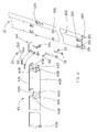
- FIG. 1 is an isometric view of an embodiment of a support assembly supporting photovoltaic panels in accordance with the present disclosure.
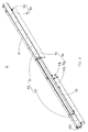
- FIG. 2 is a perspective view of the embodiment of a support unit when packaged and transported in accordance with the present disclosure.
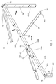
- FIG. 3 is a perspective view of the embodiment of the support unit when used in accordance with the present disclosure.
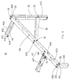
- FIG. 4 is an isometric view of the embodiment of the support unit when used in accordance with the present disclosure.
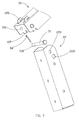
- FIG. 5 is a partially disassembled view of the embodiment of a support beam and a second standing post in accordance with the present disclosure.
- FIG. 6 is a partially disassembled view of the embodiment of the support beam and a first horizontal beam in accordance with the present disclosure.
- a support assembly 1000 for supporting photovoltaic panels 60 comprises a plurality of support units 11 connected one by one.
- Each of the plurality of support units 11 comprises a support beam 10, a pair of standing posts 20, a strengthening bar 30 and at least one horizontal beam 40.
- the pair of standing posts 20, the strengthening bar 30 and the at least one horizontal beam 40 are pivotably mounted on the support beam 10.
- the pair of standing post 20 and the strengthening bar 30 rotate relative to the support beam 10 and are received in the support beam 10 respectively, and the at least one horizontal beam 40 rotates relative to the support beam 10 and is disposed in parallel to the support beam 10, when each of the plurality of support units 11 is packaged and transported.
- the support unit 11 has a regular shape and is convenient for transportation when packaged in this way.
- the at least one horizontal beam 40 is connected to the neighboring support unit 11, the pair of standing posts 20 are unwound and disposed in parallel and the strengthening bar 30 rotates relative to the support beam 10 to constitute a triangle with the support beam 10 and one of the pair of standing posts 20 collectively.
- the support beam 10 comprises a top portion 100 and a pair of side portions 101 perpendicularly extending from two edges of the top portion 100 respectively.
- the top portion 100 and the pair of side portions 101 collectively define a receiving groove 102 used to receive the pair of standing posts 20 and the strengthening bar 30, as shown in FIG. 2 .
- a cross section of the receiving groove 102 is in a U shape.
- the top portion 100 comprises a plurality of latching portions 105 and a plurality of stopper portions 106 to secure the photovoltaic panels 60 thereon.
- the plurality of latching portions 105 and the plurality of stopper portions 106 are punched from the top portion 100 in two parallel rows, two of the plurality of latching portions 105 and two of the plurality of stopper portions 106 are disposed side by side, respectively.
- Each of the pair of the side portions 101 defines a plurality of fixing holes 103 arranged in order.
- the plurality of fixing holes 103 are configured to install the standing post 20 and the strengthening bar 30 by use of connecting shafts 51 onto the support beam 10 respectively.
- inclination of the support beam 10 is adjustable by matching one end of the strengthening bar 30 with different fixing holes 103 in the side portions 101.
- a connecting member 50 is used to pivotably mount the pair of standing posts 20, the strengthening bar 30 and the at least one horizontal beam 40 to the support beam 10 and comprises a connecting shaft 51 and a cotter pin 52.
- the connecting shaft 51 defines a plurality of shaft holes 510. Each of the plurality of shaft holes 510 is a through hole along the radial direction of the connecting shaft 51.
- the cotter pin 52 is inserted into the shaft hole 510 to engage with the connecting shaft 51 to prevent the connecting shaft 51 disengaging.
- the connecting member 50 may be a bolt with a nut or a rivet.
- the pair of standing posts 20 comprise a first standing post 21 and a second standing post 22 in parallel with each other.
- cross sections of the first standing post 21 and the second standing post 22 are in a U-shape, respectively.
- one end of the first standing post 21 is pivotably mounted on the support beam 10, and the other end is securely mounted on a mounting ground.
- the first standing post 21 defines a pair of first securing holes 210 and a plurality of first strengthen holes 212.
- the pair of first securing holes 210 are located on one end of the first standing post 21 and engage with the corresponding fixing hole 103 by use of connecting shafts 51 to pivotably mount the first standing post 21 onto the support beam 10, then the cotter pin 52 is inserted into the shaft hole 510 to prevent the connecting shaft 51 disengaging.
- the first standing post 21 rotates around the connecting shaft 51 and is received in the receiving groove 102 when packaged and/or transported. When used, the first standing post 21 should be rotated along the arrowhead direction as shown in FIG. 3 .
- the plurality of first strengthen holes 212 are evenly apart from each other and arranged in pairs to engage with the strengthening bar 30.
- the strengthening bar 30 with two ends is mounted to the support beam 10 and the first standing post 21 respectively.
- the strengthening bar 30 defines two pairs of second strengthen holes 300.
- the two pairs of second strengthen holes 300 are located on the two ends of the strengthening bar 30 and engage with the corresponding fixing hole 103 and the corresponding first strengthen hole 212 by use of connecting shafts 51 respectively.
- the cotter pin 52 is inserted into the corresponding shaft hole 510 to prevent the corresponding connecting shaft 51 disengaging.
- the support beam 10, the first standing post 21 and the strengthening bar 30 collectively configure a triangle to avoid distortion.
- one end of the strengthening bar 30 rotates around one connecting shaft 51 relative to the support beam 10 by disengaging with the first standing post 21 and is received in the receiving groove 102.
- the strengthening bar 30 should be rotated along the arrowhead direction as shown in FIG. 3 .
- the second standing post 22 and the first standing post 21 rotate around the respective connecting shaft 51 relative to the support beam 10.
- a length of the second standing post 22 is shorter than that of the first standing post 21 so that the support beam 10 is inclined to a certain angle.
- the second standing post 22 defines a pairs of second securing holes 220 and a pair of latching holes 222.
- the pair of the second securing holes 220 is defined in one end of the second standing post 22, and the pair of latching holes 222 are defined beside the pair of the second securing holes 220.
- the connecting shaft 51 passes through the fixing hole 103 and the pair of second securing holes 220 to pivotably mount the second standing post 22 onto the support beam 10, and the cotter pin 52 is inserted into the shaft hole 510 to prevent the connecting shaft 51 disengaging.
- the second standing post 22 rotates around the corresponding connecting shaft 51 relative to the support beam 10 and is received in the receiving groove 102.
- Each side portion 101 of the support beam 10 comprises a latching clip 107.
- the latching clip 107 is located on one end of the support beam 10 neighboring to the second standing post 22.
- the latching clip 107 is bent towards the receiving groove 102.
- the latching clip 107 is integrally formed with the side portion 101.
- each of the pair of the side portions 101 further comprises a plurality of roll portions 104 arranged in order.
- Each of the plurality of roll portions 104 is engaged with the at least one horizontal beam 40 to pivotably mount the at least one horizontal beam 40 onto the support beam 10.
- the plurality of roll portions 104 are integrally formed with the side portion 101.
- the at least one horizontal beam 40 with one end is pivotably mounted to the support beam 10 and the other end is configured to connect to a neighboring support unit 11.
- the at least one horizontal beam 40 comprises a first horizontal beam 41 and a second horizontal beam 42.
- cross sections of the first horizontal beam 41 and the second horizontal beam 42 are in a U shape, respectively.
- the first horizontal beam 41 is pivotably mounted between two neighboring support beams 10.
- the first horizontal beam 41 comprises a first bottom portion 410 and a pair of first side walls 412 bent in parallel from two edges of the first bottom portion 410 respectively.
- the first horizontal beam 41 defines two first double sleeves 414 on two ends thereof and on the same side of the side wall 412.
- the first double sleeve 414 matches with the corresponding roll portion 104 to pivotably connect one end of the first horizontal beam 41 to the support beam 10 by use of the connecting shaft 51.
- the cotter pin 52 is inserted into the corresponding shaft hole 510 to prevent the connecting shaft 51 disengaging.
- the other end of the first horizontal beam 41 is mounted onto the neighboring support beam 10 by the same method.
- the first horizontal beam 41 is mounted between two support units 11 to support the photovoltaic panel 60.
- one end of the first horizontal beam 41 rotates around the corresponding connecting shaft 51 relative to the support beam 10 by removing the other connecting shaft 51 and is folded to get close to the side portion 101 of the support beam 10.
- the first horizontal beam 41 should be rotated along the arrowhead direction as shown in FIG. 3 .
- the first horizontal beam 41 further defines a plurality of first drainage holes 416 on joint portions between the first bottom portion 410 and the pair of first side walls 412 for draining.
- the second horizontal beam 42 is parallel with the first horizontal beam 41 and pivotably mounted between two neighboring support beams 10.
- the second horizontal beam 42 comprises a support portion 43 and a connecting portion 44.
- One end of the support portion 43 is movably mounted on one end of the connecting portion 44 and the other end is mounted on the side portion 101 of the support beam 10.
- the other end of the connecting portion 44 is movably mounted on the side portion 101 of the neighboring support beam 10.
- rotation plane of the connecting portion 44 rotating relative to the support beam 10 is perpendicular to that of the support portion 43 rotating relative to the connecting portion 44, thus, it is convenient to mount or disassemble the support portion 43 and to fold the second horizontal beam 42 close to the support beam 10.
- the support portion 43 comprises a second bottom portion 430, a pair of second side walls 431 bent in parallel from two edges of the second bottom portion 430 respectively and a cover portion 432 parallel with the second bottom portion 430.
- the cover portion 432 is bent along one of the pair of second side walls 431 and is spaced apart from the other of the pair of second side walls 431.
- a receiving portion 433 is cooperatively defined by the second bottom portion 430, the pair of the second side walls 431 and the cover portion 432.
- the receiving portion 433 is used to receive power cords (not shown) from a jack box 61 of the photovoltaic panel 60 (as shown in FIG. 1 ).
- the support portion 43 defines a plurality of latching notches 434 to securely install the photovoltaic panel 60.
- Each of the plurality of latching notches 434 is formed by punching a part of the pair of second side walls 431 and the cover portion 432.
- the power cords are distributed into the receiving portion 433 through the plurality of latching notches 434.
- the second horizontal beam 42 defines a plurality of second watering drainage holes 435 on joint portions between the second bottom portion 430 and the pair of second side walls 431 for draining.
- a single sleeve 436 is defined on one of the pair of second side walls 431 to engage with the corresponding roll portion 104 so as to mount the second horizontal beam 42 on the support beam 10.
- the support assembly 1000 is configured by a plurality of support units 11 to enlarge support area for photovoltaic panels 60 freely.
- a pair of protruding walls 437 are disposed on two side walls 431 of the end of the support portion 43 respectively and define a pair of first through holes 439 correspondingly.
- a protruding post 438 is protruded outwardly from one of the pair of protruding walls 437 towards the receiving portion 433.
- the protruding post 438 and the single sleeve 436 are located on two opposite sides of the second side wall 431.
- the pair of first through holes 439 and the protruding post 438 are engaged with the connecting portion 44 to movably mount the support portion 43 onto the connecting portion 44.
- a cross section of the connecting portion 44 is in a U shape.
- the connecting portion 44 comprises a horizontal double sleeve 440 and a perpendicular double sleeve 441 perpendicular to the horizontal double sleeve 440, and defines a pair of second through holes 442.
- the horizontal double sleeve 440 is located on the bottom of the connecting portion 44 and engaged with the protruding post 438 to pivotably mount the connecting portion 44 onto the support portion 43 by use of the connecting shaft 51.
- the support portion 43 is rotated relative to the connecting portion 44 away from the photovoltaic panel 60.
- the pair of second through holes 442 are located on two sides of the connecting portion 44 and engaged with the pair of first through holes 439 to securely mount the support portion 43 onto the connecting portion 44 by use of the connecting shaft 51. Then, the cotter pin 52 is inserted into the corresponding shaft hole 510 to prevent the connecting shaft 51 disengaging.
- the perpendicular double sleeve 441 is located on the same side of the second horizontal beam 42 with the single sleeve 436. The perpendicular double sleeve 441 matches with the corresponding roll portion 104 to pivotably connect the connecting portion 44 to the side portion 101 by use of the connecting shaft 51, and the cotter pin 52 is inserted into the corresponding shaft hole 510 to prevent the connecting shaft 51 disengaging.
- the connecting portion 44 When packaged and/or transported, the connecting portion 44 is rotated around the connecting shaft 51 with the support portion 43 and the second horizontal beam 42 is folded to be close to the side portion 101.
- the second horizontal beam 42, the second horizontal beam 42 should be rotated along the arrowhead direction as shown in FIG. 3 .
- the first standing post 21, the second standing post 22 and the strengthening bar 30 are pivotably mounted on the support beam 10 by use of the connecting shafts 51 and rotate around the corresponding connecting shaft 51 relative to the support beam 10 to be received into the receiving groove 102 when packaged and/or transported.
- the first standing post 21, the second standing post 22 and the strengthening bar 30 rotate around the corresponding connecting shaft 51 to open each other respectively.
- the first horizontal beam 41 is pivotably mounted on the roll portion 104 by use of the connecting shaft 51 and rotates around the connecting shaft 51 to be folded to get close to the side portion 101 when packaged and/or transported.
- the connecting portion 44 and the support portion 43 are pivotably mounted on the support beam 10 by use of the connecting shaft 51.
- the connecting portion 44 rotates around the corresponding connecting shaft 51 to fold the second horizontal beam 42 to get close to the side portion 101.
- the support portion 43 rotates around the corresponding connecting shaft 51 relative to the connecting portion 44 to distribute the power cords conveniently.
Landscapes
- Engineering & Computer Science (AREA)
- Physics & Mathematics (AREA)
- Life Sciences & Earth Sciences (AREA)
- Sustainable Development (AREA)
- Sustainable Energy (AREA)
- Thermal Sciences (AREA)
- Chemical & Material Sciences (AREA)
- Combustion & Propulsion (AREA)
- Mechanical Engineering (AREA)
- General Engineering & Computer Science (AREA)
- Photovoltaic Devices (AREA)
- Packaging Frangible Articles (AREA)
Applications Claiming Priority (1)
| Application Number | Priority Date | Filing Date | Title |
|---|---|---|---|
| CN201020230857XU CN201820766U (zh) | 2010-06-21 | 2010-06-21 | 太阳能光电板安装支架 |
Publications (3)
| Publication Number | Publication Date |
|---|---|
| EP2398065A2 true EP2398065A2 (de) | 2011-12-21 |
| EP2398065A3 EP2398065A3 (de) | 2015-10-28 |
| EP2398065B1 EP2398065B1 (de) | 2019-12-25 |
Family
ID=43918710
Family Applications (1)
| Application Number | Title | Priority Date | Filing Date |
|---|---|---|---|
| EP10193176.4A Active EP2398065B1 (de) | 2010-06-21 | 2010-11-30 | Stützanordnung für Fotovoltaikpaneele |
Country Status (3)
| Country | Link |
|---|---|
| US (1) | US9115915B2 (de) |
| EP (1) | EP2398065B1 (de) |
| CN (1) | CN201820766U (de) |
Cited By (5)
| Publication number | Priority date | Publication date | Assignee | Title |
|---|---|---|---|---|
| WO2013153200A3 (de) * | 2012-04-13 | 2015-01-22 | Richard Brink Gmbh & Co. Kg | Bausatz einer halteeinrichtung für solarelemente |
| CN105490623A (zh) * | 2015-12-16 | 2016-04-13 | 常熟高嘉能源科技有限公司 | 一种高强度光伏组件用支架 |
| CN107477053A (zh) * | 2017-09-19 | 2017-12-15 | 中广核研究院有限公司 | 高低支撑梁用辅助件 |
| EP4148339A1 (de) * | 2021-09-13 | 2023-03-15 | CEP-IP Ltd | Anordnung für ein tragbares solarenergiesystem |
| EP4148979A1 (de) * | 2021-09-13 | 2023-03-15 | CEP-IP Ltd | Faltbare fotovoltaische anordnung für ein tragbares solarenergiesystem |
Families Citing this family (40)
| Publication number | Priority date | Publication date | Assignee | Title |
|---|---|---|---|---|
| US8534007B2 (en) * | 2009-02-24 | 2013-09-17 | Sunpower Corporation | Photovoltaic assemblies and methods for transporting |
| US8413824B2 (en) * | 2009-11-23 | 2013-04-09 | Albert Louis Cabassa | Vertically-oriented folding wire caddy |
| US9462734B2 (en) | 2010-04-27 | 2016-10-04 | Alion Energy, Inc. | Rail systems and methods for installation and operation of photovoltaic arrays |
| US9343592B2 (en) | 2010-08-03 | 2016-05-17 | Alion Energy, Inc. | Electrical interconnects for photovoltaic modules and methods thereof |
| US20120145848A1 (en) * | 2010-12-10 | 2012-06-14 | David Schuff | Pier cap cleat |
| US9641123B2 (en) | 2011-03-18 | 2017-05-02 | Alion Energy, Inc. | Systems for mounting photovoltaic modules |
| WO2012167774A2 (de) * | 2011-06-08 | 2012-12-13 | Schletter Gmbh | Ständer für pv-module |
| TWI433333B (zh) * | 2011-07-05 | 2014-04-01 | Au Optronics Corp | 太陽能面板模組 |
| CN102983183A (zh) * | 2011-09-05 | 2013-03-20 | 杜邦太阳能有限公司 | 太阳能系统可调安装结构 |
| CN102983184B (zh) * | 2011-09-05 | 2015-07-08 | 日轻金Act株式会社 | 太阳能面板架台 |
| US9003726B2 (en) * | 2011-11-14 | 2015-04-14 | The RAQ, LLC | System and method for establishing a self-aligning mounting system for mounting photovoltaic modules |
| CN102494421B (zh) * | 2011-12-01 | 2013-11-13 | 苏州瑞得恩光能科技有限公司 | 导轨安装架 |
| CN103187463A (zh) * | 2011-12-29 | 2013-07-03 | 富昱能源科技(昆山)有限公司 | 支架装置 |
| CA2860607A1 (en) * | 2012-03-15 | 2013-09-19 | Magna International Inc. | Solar panel mounting structure |
| US9352941B2 (en) | 2012-03-20 | 2016-05-31 | Alion Energy, Inc. | Gantry crane vehicles and methods for photovoltaic arrays |
| EP2884545B1 (de) * | 2012-05-03 | 2023-03-29 | Changzhou Trina Solar Energy Co., Ltd. | Montagestruktur für eine gefaltete fotovoltaikanlage und montageverfahren dafür |
| MX373922B (es) * | 2012-05-16 | 2020-07-10 | Alion Energy Inc | Sistemas de soporte giratorio para modulos fotovoltaicos y metodos de los mismos. |
| US8936164B2 (en) * | 2012-07-06 | 2015-01-20 | Industrial Origami, Inc. | Solar panel rack |
| CN102916063A (zh) * | 2012-10-15 | 2013-02-06 | 东莞市中海光电材料有限公司 | 太阳能电池板组件、太阳能电池板安装系统及其安装方法 |
| CN103056861A (zh) * | 2013-01-23 | 2013-04-24 | 上海理工大学 | 可拆卸折叠的工具车 |
| CN103050893A (zh) * | 2013-01-24 | 2013-04-17 | 青岛乾程电子科技有限公司 | 一种电力环网柜终端装置 |
| JP5499194B1 (ja) * | 2013-02-12 | 2014-05-21 | 株式会社 沢木組 | ソーラーパネル取付架台 |
| JP6475246B2 (ja) | 2013-09-05 | 2019-02-27 | アリオン エナジー,インコーポレーテッド | 太陽光発電モジュールのレールベースアレイを保守するためのシステム、輸送手段、及び方法 |
| US9453660B2 (en) | 2013-09-11 | 2016-09-27 | Alion Energy, Inc. | Vehicles and methods for magnetically managing legs of rail-based photovoltaic modules during installation |
| JP6146880B2 (ja) * | 2014-06-23 | 2017-06-14 | 株式会社ソーラーリソースジャパン | 太陽光発電パネル用架台 |
| JP6478383B2 (ja) * | 2014-09-17 | 2019-03-06 | 株式会社タナック | モジュール取付け用のフレームおよびフレームセット |
| JP6442739B2 (ja) * | 2014-11-21 | 2018-12-26 | 日本エフ・アール・ピー株式会社 | 太陽光パネル用の支持組立体 |
| US10171027B2 (en) | 2015-03-02 | 2019-01-01 | Sunpower Corporation | Photovoltaic module mount |
| CN107835921B (zh) * | 2015-05-18 | 2020-03-10 | 阿利昂能源公司 | 用于安装光伏模块的系统和方法 |
| WO2017044566A1 (en) | 2015-09-11 | 2017-03-16 | Alion Energy, Inc. | Wind screens for photovoltaic arrays and methods thereof |
| US20170126168A1 (en) * | 2015-11-03 | 2017-05-04 | Gamechange Solar Llc | Grid-lite roof system for solar panel installations |
| JP6698331B2 (ja) * | 2015-12-14 | 2020-05-27 | アルファブロス株式会社 | 太陽電池パネルの架台 |
| IT201800004039A1 (it) * | 2018-03-28 | 2019-09-28 | Elianto S R L | Struttura di sostegno di un impianto solare termodinamico a concentrazione lineare dotato di riflettori fresnel |
| CN110601641B (zh) * | 2019-09-17 | 2022-12-20 | 江苏凯撒型材科技有限公司 | 一种标准化光伏支架系统 |
| ES1248271Y (es) * | 2020-05-07 | 2020-09-14 | Manonelles Montserrat Bonjoch | Soporte de modulos fotovoltaicos |
| CN112923584B (zh) * | 2021-03-25 | 2022-03-04 | 中国科学院西北生态环境资源研究院 | 光聚式防冻胀聚热装置及其路基 |
| US11817814B2 (en) * | 2021-04-28 | 2023-11-14 | James E. Straeter | Ground mounted solar power assembly |
| EP4148984A1 (de) * | 2021-09-13 | 2023-03-15 | CEP-IP Ltd | Photovoltaische anordnung für ein tragbares solarenergiesystem |
| CN114135746B (zh) * | 2021-12-01 | 2024-05-07 | 四川波凡同创机器人有限公司 | 一种木质三角架、生产方法以及生产线 |
| DE202022105414U1 (de) | 2022-09-27 | 2022-10-06 | König GmbH & Co. KG | Tragkonstruktionsmontagesystem für Photovoltaik-Module |
Family Cites Families (12)
| Publication number | Priority date | Publication date | Assignee | Title |
|---|---|---|---|---|
| US1714698A (en) * | 1926-11-08 | 1929-05-28 | Frank M Stoll | Latch mechanism for hinge members |
| US4269173A (en) * | 1978-04-27 | 1981-05-26 | Libbey-Owens-Ford Company | System for mounting solar collector panels |
| JPS6140063A (ja) * | 1984-07-31 | 1986-02-26 | Toshiba Electric Equip Corp | 太陽電池取付け装置 |
| GB2238827B (en) * | 1989-12-08 | 1994-03-30 | Heywood Williams Ltd | Hinge |
| JPH09235844A (ja) * | 1996-02-29 | 1997-09-09 | Shiroki Corp | 太陽電池取付け構造 |
| BE1013890A3 (nl) * | 2001-01-04 | 2002-11-05 | Verheyen Hugo Gerard | Werktafel. |
| DE102004023043B4 (de) * | 2004-05-06 | 2007-01-18 | Doko, Gilbert, Dr.-Ing. | Transportable Anlage zur Solarstromerzeugung |
| US20080030029A1 (en) * | 2006-06-19 | 2008-02-07 | Mcginnis Glenn M | Double hung entry door bracing system |
| US7717376B2 (en) * | 2006-10-17 | 2010-05-18 | Sparks Jr Douglas M | Bracket devices and systems |
| CN102089601A (zh) * | 2008-05-08 | 2011-06-08 | 美国太阳能股份有限公司 | 安装于平屋顶的太阳能面板支架系统 |
| US8256169B2 (en) * | 2009-03-20 | 2012-09-04 | Northern States Metals Company | Support system for solar panels |
| US8272189B2 (en) * | 2009-04-29 | 2012-09-25 | Wuxi Suntech Power Co., Ltd. | PV module frame, PV module and installation system thereof |
-
2010
- 2010-06-21 CN CN201020230857XU patent/CN201820766U/zh not_active Expired - Lifetime
- 2010-09-23 US US12/888,416 patent/US9115915B2/en active Active
- 2010-11-30 EP EP10193176.4A patent/EP2398065B1/de active Active
Non-Patent Citations (1)
| Title |
|---|
| None |
Cited By (8)
| Publication number | Priority date | Publication date | Assignee | Title |
|---|---|---|---|---|
| WO2013153200A3 (de) * | 2012-04-13 | 2015-01-22 | Richard Brink Gmbh & Co. Kg | Bausatz einer halteeinrichtung für solarelemente |
| CN105490623A (zh) * | 2015-12-16 | 2016-04-13 | 常熟高嘉能源科技有限公司 | 一种高强度光伏组件用支架 |
| CN107477053A (zh) * | 2017-09-19 | 2017-12-15 | 中广核研究院有限公司 | 高低支撑梁用辅助件 |
| EP4148339A1 (de) * | 2021-09-13 | 2023-03-15 | CEP-IP Ltd | Anordnung für ein tragbares solarenergiesystem |
| EP4148979A1 (de) * | 2021-09-13 | 2023-03-15 | CEP-IP Ltd | Faltbare fotovoltaische anordnung für ein tragbares solarenergiesystem |
| WO2023037001A1 (en) * | 2021-09-13 | 2023-03-16 | CEP-IP Ltd | Foldable photovoltaic assembly for a portable solar energy system |
| WO2023037003A1 (en) * | 2021-09-13 | 2023-03-16 | CEP-IP Ltd | Assembly for a portable solar energy system |
| US20240396492A1 (en) * | 2021-09-13 | 2024-11-28 | CEP-IP Ltd | Assembly for a portable solar energy system |
Also Published As
| Publication number | Publication date |
|---|---|
| EP2398065A3 (de) | 2015-10-28 |
| EP2398065B1 (de) | 2019-12-25 |
| US20110309215A1 (en) | 2011-12-22 |
| CN201820766U (zh) | 2011-05-04 |
| US9115915B2 (en) | 2015-08-25 |
Similar Documents
| Publication | Publication Date | Title |
|---|---|---|
| US9115915B2 (en) | Support assembly for photovoltaic panels | |
| US10506880B2 (en) | Utility rack having end supports with folding cross-members | |
| US10508005B2 (en) | Assembly for lifting or supporting a load, and members and connectors for use in same | |
| US10041269B2 (en) | Wind turbine tower section, wind turbine tower and assembly method | |
| US20070175847A1 (en) | Rapidly assembleable and disassembleable display rack | |
| EP3212358B1 (de) | Verschlussplattenverbindung für bewehrungsstäbe mit einer stange | |
| CN102291953A (zh) | 安装电子设备的机柜 | |
| US20130270332A1 (en) | Modular Panel-Packing Box | |
| US6283045B1 (en) | Foldable table | |
| CN106677510B (zh) | 操作平台、塔筒片体、塔筒段、塔筒及风力发电机组 | |
| US20210115903A1 (en) | Wind turbine mast section, wind turbine mast and assembly method | |
| US20180195304A1 (en) | Banner frame with anchor stakes | |
| CN112969852B (zh) | 风力涡轮机桅杆部段、风力涡轮机桅杆和组装方法 | |
| CA3015262C (en) | Play structure and bracket for play structure | |
| US20080116159A1 (en) | Show stand | |
| CN205955052U (zh) | 折叠栏杆及防护平台 | |
| WO2019057669A1 (fr) | Abri comprenant une pluralite de modules adaptes pour etre solidarises ensemble afin de former une structure maillee du type « gridshell » | |
| EP2843157A1 (de) | Modulares Gerüstsystem mit Trolley | |
| US20250374467A1 (en) | Mounting assemblies for remote radio units | |
| JP2007169025A (ja) | ホイールコンベア | |
| KR101172993B1 (ko) | 상판과 다리가 접히는 접이식 책상 | |
| FR3100828A1 (fr) | Structure pliable de travail en encorbellement comportant des pieds pour l’empilement | |
| KR20120013561A (ko) | 크기 가변형 랙 구조물 | |
| WO1981001163A1 (en) | Scaffolding which may be dismantled | |
| TWM504151U (zh) | 風力機葉片繫固系統 |
Legal Events
| Date | Code | Title | Description |
|---|---|---|---|
| AK | Designated contracting states |
Kind code of ref document: A2 Designated state(s): AL AT BE BG CH CY CZ DE DK EE ES FI FR GB GR HR HU IE IS IT LI LT LU LV MC MK MT NL NO PL PT RO RS SE SI SK SM TR |
|
| AX | Request for extension of the european patent |
Extension state: BA ME |
|
| PUAI | Public reference made under article 153(3) epc to a published international application that has entered the european phase |
Free format text: ORIGINAL CODE: 0009012 |
|
| PUAL | Search report despatched |
Free format text: ORIGINAL CODE: 0009013 |
|
| AK | Designated contracting states |
Kind code of ref document: A3 Designated state(s): AL AT BE BG CH CY CZ DE DK EE ES FI FR GB GR HR HU IE IS IT LI LT LU LV MC MK MT NL NO PL PT RO RS SE SI SK SM TR |
|
| AX | Request for extension of the european patent |
Extension state: BA ME |
|
| 17P | Request for examination filed |
Effective date: 20160426 |
|
| RBV | Designated contracting states (corrected) |
Designated state(s): AL AT BE BG CH CY CZ DE DK EE ES FI FR GB GR HR HU IE IS IT LI LT LU LV MC MK MT NL NO PL PT RO RS SE SI SK SM TR |
|
| STAA | Information on the status of an ep patent application or granted ep patent |
Free format text: STATUS: EXAMINATION IS IN PROGRESS |
|
| 17Q | First examination report despatched |
Effective date: 20180718 |
|
| REG | Reference to a national code |
Ref country code: DE Ref legal event code: R079 Ref document number: 602010062494 Country of ref document: DE Free format text: PREVIOUS MAIN CLASS: H01L0031042000 Ipc: H02S0030200000 |
|
| GRAP | Despatch of communication of intention to grant a patent |
Free format text: ORIGINAL CODE: EPIDOSNIGR1 |
|
| STAA | Information on the status of an ep patent application or granted ep patent |
Free format text: STATUS: GRANT OF PATENT IS INTENDED |
|
| RIC1 | Information provided on ipc code assigned before grant |
Ipc: F24S 25/65 20180101ALI20190716BHEP Ipc: H02S 30/20 20140101AFI20190716BHEP |
|
| RIC1 | Information provided on ipc code assigned before grant |
Ipc: F24S 25/632 20180101ALI20190729BHEP Ipc: F24S 25/12 20180101ALI20190729BHEP Ipc: H02S 20/10 20140101ALI20190729BHEP Ipc: F24S 25/65 20180101ALI20190729BHEP Ipc: H02S 30/20 20140101AFI20190729BHEP |
|
| INTG | Intention to grant announced |
Effective date: 20190813 |
|
| RIN1 | Information on inventor provided before grant (corrected) |
Inventor name: WANG, REN Inventor name: LU, KAI-MING |
|
| GRAS | Grant fee paid |
Free format text: ORIGINAL CODE: EPIDOSNIGR3 |
|
| GRAA | (expected) grant |
Free format text: ORIGINAL CODE: 0009210 |
|
| STAA | Information on the status of an ep patent application or granted ep patent |
Free format text: STATUS: THE PATENT HAS BEEN GRANTED |
|
| AK | Designated contracting states |
Kind code of ref document: B1 Designated state(s): AL AT BE BG CH CY CZ DE DK EE ES FI FR GB GR HR HU IE IS IT LI LT LU LV MC MK MT NL NO PL PT RO RS SE SI SK SM TR |
|
| REG | Reference to a national code |
Ref country code: GB Ref legal event code: FG4D |
|
| REG | Reference to a national code |
Ref country code: CH Ref legal event code: EP |
|
| REG | Reference to a national code |
Ref country code: AT Ref legal event code: REF Ref document number: 1218254 Country of ref document: AT Kind code of ref document: T Effective date: 20200115 |
|
| REG | Reference to a national code |
Ref country code: DE Ref legal event code: R096 Ref document number: 602010062494 Country of ref document: DE |
|
| REG | Reference to a national code |
Ref country code: IE Ref legal event code: FG4D |
|
| REG | Reference to a national code |
Ref country code: CH Ref legal event code: NV Representative=s name: RENTSCH PARTNER AG, CH |
|
| RAP2 | Party data changed (patent owner data changed or rights of a patent transferred) |
Owner name: HON HAI PRECISION INDUSTRY CO., LTD. Owner name: HONG FU JIN PRECISION INDUSTRY (SHENZHEN) CO., LTD. |
|
| REG | Reference to a national code |
Ref country code: NL Ref legal event code: MP Effective date: 20191225 |
|
| PG25 | Lapsed in a contracting state [announced via postgrant information from national office to epo] |
Ref country code: LV Free format text: LAPSE BECAUSE OF FAILURE TO SUBMIT A TRANSLATION OF THE DESCRIPTION OR TO PAY THE FEE WITHIN THE PRESCRIBED TIME-LIMIT Effective date: 20191225 Ref country code: SE Free format text: LAPSE BECAUSE OF FAILURE TO SUBMIT A TRANSLATION OF THE DESCRIPTION OR TO PAY THE FEE WITHIN THE PRESCRIBED TIME-LIMIT Effective date: 20191225 Ref country code: GR Free format text: LAPSE BECAUSE OF FAILURE TO SUBMIT A TRANSLATION OF THE DESCRIPTION OR TO PAY THE FEE WITHIN THE PRESCRIBED TIME-LIMIT Effective date: 20200326 Ref country code: NO Free format text: LAPSE BECAUSE OF FAILURE TO SUBMIT A TRANSLATION OF THE DESCRIPTION OR TO PAY THE FEE WITHIN THE PRESCRIBED TIME-LIMIT Effective date: 20200325 Ref country code: LT Free format text: LAPSE BECAUSE OF FAILURE TO SUBMIT A TRANSLATION OF THE DESCRIPTION OR TO PAY THE FEE WITHIN THE PRESCRIBED TIME-LIMIT Effective date: 20191225 Ref country code: BG Free format text: LAPSE BECAUSE OF FAILURE TO SUBMIT A TRANSLATION OF THE DESCRIPTION OR TO PAY THE FEE WITHIN THE PRESCRIBED TIME-LIMIT Effective date: 20200325 Ref country code: FI Free format text: LAPSE BECAUSE OF FAILURE TO SUBMIT A TRANSLATION OF THE DESCRIPTION OR TO PAY THE FEE WITHIN THE PRESCRIBED TIME-LIMIT Effective date: 20191225 |
|
| REG | Reference to a national code |
Ref country code: LT Ref legal event code: MG4D |
|
| PG25 | Lapsed in a contracting state [announced via postgrant information from national office to epo] |
Ref country code: HR Free format text: LAPSE BECAUSE OF FAILURE TO SUBMIT A TRANSLATION OF THE DESCRIPTION OR TO PAY THE FEE WITHIN THE PRESCRIBED TIME-LIMIT Effective date: 20191225 Ref country code: RS Free format text: LAPSE BECAUSE OF FAILURE TO SUBMIT A TRANSLATION OF THE DESCRIPTION OR TO PAY THE FEE WITHIN THE PRESCRIBED TIME-LIMIT Effective date: 20191225 |
|
| PG25 | Lapsed in a contracting state [announced via postgrant information from national office to epo] |
Ref country code: AL Free format text: LAPSE BECAUSE OF FAILURE TO SUBMIT A TRANSLATION OF THE DESCRIPTION OR TO PAY THE FEE WITHIN THE PRESCRIBED TIME-LIMIT Effective date: 20191225 |
|
| PG25 | Lapsed in a contracting state [announced via postgrant information from national office to epo] |
Ref country code: EE Free format text: LAPSE BECAUSE OF FAILURE TO SUBMIT A TRANSLATION OF THE DESCRIPTION OR TO PAY THE FEE WITHIN THE PRESCRIBED TIME-LIMIT Effective date: 20191225 Ref country code: PT Free format text: LAPSE BECAUSE OF FAILURE TO SUBMIT A TRANSLATION OF THE DESCRIPTION OR TO PAY THE FEE WITHIN THE PRESCRIBED TIME-LIMIT Effective date: 20200520 Ref country code: NL Free format text: LAPSE BECAUSE OF FAILURE TO SUBMIT A TRANSLATION OF THE DESCRIPTION OR TO PAY THE FEE WITHIN THE PRESCRIBED TIME-LIMIT Effective date: 20191225 Ref country code: RO Free format text: LAPSE BECAUSE OF FAILURE TO SUBMIT A TRANSLATION OF THE DESCRIPTION OR TO PAY THE FEE WITHIN THE PRESCRIBED TIME-LIMIT Effective date: 20191225 Ref country code: CZ Free format text: LAPSE BECAUSE OF FAILURE TO SUBMIT A TRANSLATION OF THE DESCRIPTION OR TO PAY THE FEE WITHIN THE PRESCRIBED TIME-LIMIT Effective date: 20191225 |
|
| PG25 | Lapsed in a contracting state [announced via postgrant information from national office to epo] |
Ref country code: SM Free format text: LAPSE BECAUSE OF FAILURE TO SUBMIT A TRANSLATION OF THE DESCRIPTION OR TO PAY THE FEE WITHIN THE PRESCRIBED TIME-LIMIT Effective date: 20191225 Ref country code: SK Free format text: LAPSE BECAUSE OF FAILURE TO SUBMIT A TRANSLATION OF THE DESCRIPTION OR TO PAY THE FEE WITHIN THE PRESCRIBED TIME-LIMIT Effective date: 20191225 Ref country code: IS Free format text: LAPSE BECAUSE OF FAILURE TO SUBMIT A TRANSLATION OF THE DESCRIPTION OR TO PAY THE FEE WITHIN THE PRESCRIBED TIME-LIMIT Effective date: 20200425 |
|
| REG | Reference to a national code |
Ref country code: DE Ref legal event code: R097 Ref document number: 602010062494 Country of ref document: DE |
|
| PG25 | Lapsed in a contracting state [announced via postgrant information from national office to epo] |
Ref country code: DK Free format text: LAPSE BECAUSE OF FAILURE TO SUBMIT A TRANSLATION OF THE DESCRIPTION OR TO PAY THE FEE WITHIN THE PRESCRIBED TIME-LIMIT Effective date: 20191225 Ref country code: ES Free format text: LAPSE BECAUSE OF FAILURE TO SUBMIT A TRANSLATION OF THE DESCRIPTION OR TO PAY THE FEE WITHIN THE PRESCRIBED TIME-LIMIT Effective date: 20191225 |
|
| PLBE | No opposition filed within time limit |
Free format text: ORIGINAL CODE: 0009261 |
|
| STAA | Information on the status of an ep patent application or granted ep patent |
Free format text: STATUS: NO OPPOSITION FILED WITHIN TIME LIMIT |
|
| REG | Reference to a national code |
Ref country code: AT Ref legal event code: MK05 Ref document number: 1218254 Country of ref document: AT Kind code of ref document: T Effective date: 20191225 |
|
| PG25 | Lapsed in a contracting state [announced via postgrant information from national office to epo] |
Ref country code: SI Free format text: LAPSE BECAUSE OF FAILURE TO SUBMIT A TRANSLATION OF THE DESCRIPTION OR TO PAY THE FEE WITHIN THE PRESCRIBED TIME-LIMIT Effective date: 20191225 |
|
| 26N | No opposition filed |
Effective date: 20200928 |
|
| PG25 | Lapsed in a contracting state [announced via postgrant information from national office to epo] |
Ref country code: AT Free format text: LAPSE BECAUSE OF FAILURE TO SUBMIT A TRANSLATION OF THE DESCRIPTION OR TO PAY THE FEE WITHIN THE PRESCRIBED TIME-LIMIT Effective date: 20191225 Ref country code: IT Free format text: LAPSE BECAUSE OF FAILURE TO SUBMIT A TRANSLATION OF THE DESCRIPTION OR TO PAY THE FEE WITHIN THE PRESCRIBED TIME-LIMIT Effective date: 20191225 |
|
| PG25 | Lapsed in a contracting state [announced via postgrant information from national office to epo] |
Ref country code: PL Free format text: LAPSE BECAUSE OF FAILURE TO SUBMIT A TRANSLATION OF THE DESCRIPTION OR TO PAY THE FEE WITHIN THE PRESCRIBED TIME-LIMIT Effective date: 20191225 |
|
| PG25 | Lapsed in a contracting state [announced via postgrant information from national office to epo] |
Ref country code: MC Free format text: LAPSE BECAUSE OF FAILURE TO SUBMIT A TRANSLATION OF THE DESCRIPTION OR TO PAY THE FEE WITHIN THE PRESCRIBED TIME-LIMIT Effective date: 20191225 |
|
| PG25 | Lapsed in a contracting state [announced via postgrant information from national office to epo] |
Ref country code: LU Free format text: LAPSE BECAUSE OF NON-PAYMENT OF DUE FEES Effective date: 20201130 |
|
| REG | Reference to a national code |
Ref country code: BE Ref legal event code: MM Effective date: 20201130 |
|
| REG | Reference to a national code |
Ref country code: IE Ref legal event code: MM4A |
|
| PG25 | Lapsed in a contracting state [announced via postgrant information from national office to epo] |
Ref country code: IE Free format text: LAPSE BECAUSE OF NON-PAYMENT OF DUE FEES Effective date: 20201130 |
|
| PGFP | Annual fee paid to national office [announced via postgrant information from national office to epo] |
Ref country code: DE Payment date: 20211019 Year of fee payment: 12 Ref country code: FR Payment date: 20211109 Year of fee payment: 12 Ref country code: GB Payment date: 20211021 Year of fee payment: 12 |
|
| PGFP | Annual fee paid to national office [announced via postgrant information from national office to epo] |
Ref country code: CH Payment date: 20211116 Year of fee payment: 12 |
|
| PG25 | Lapsed in a contracting state [announced via postgrant information from national office to epo] |
Ref country code: TR Free format text: LAPSE BECAUSE OF FAILURE TO SUBMIT A TRANSLATION OF THE DESCRIPTION OR TO PAY THE FEE WITHIN THE PRESCRIBED TIME-LIMIT Effective date: 20191225 Ref country code: MT Free format text: LAPSE BECAUSE OF FAILURE TO SUBMIT A TRANSLATION OF THE DESCRIPTION OR TO PAY THE FEE WITHIN THE PRESCRIBED TIME-LIMIT Effective date: 20191225 Ref country code: CY Free format text: LAPSE BECAUSE OF FAILURE TO SUBMIT A TRANSLATION OF THE DESCRIPTION OR TO PAY THE FEE WITHIN THE PRESCRIBED TIME-LIMIT Effective date: 20191225 |
|
| PG25 | Lapsed in a contracting state [announced via postgrant information from national office to epo] |
Ref country code: MK Free format text: LAPSE BECAUSE OF FAILURE TO SUBMIT A TRANSLATION OF THE DESCRIPTION OR TO PAY THE FEE WITHIN THE PRESCRIBED TIME-LIMIT Effective date: 20191225 |
|
| PG25 | Lapsed in a contracting state [announced via postgrant information from national office to epo] |
Ref country code: BE Free format text: LAPSE BECAUSE OF NON-PAYMENT OF DUE FEES Effective date: 20201130 |
|
| REG | Reference to a national code |
Ref country code: DE Ref legal event code: R119 Ref document number: 602010062494 Country of ref document: DE |
|
| REG | Reference to a national code |
Ref country code: CH Ref legal event code: PL |
|
| GBPC | Gb: european patent ceased through non-payment of renewal fee |
Effective date: 20221130 |
|
| PG25 | Lapsed in a contracting state [announced via postgrant information from national office to epo] |
Ref country code: LI Free format text: LAPSE BECAUSE OF NON-PAYMENT OF DUE FEES Effective date: 20221130 Ref country code: CH Free format text: LAPSE BECAUSE OF NON-PAYMENT OF DUE FEES Effective date: 20221130 |
|
| PG25 | Lapsed in a contracting state [announced via postgrant information from national office to epo] |
Ref country code: GB Free format text: LAPSE BECAUSE OF NON-PAYMENT OF DUE FEES Effective date: 20221130 Ref country code: DE Free format text: LAPSE BECAUSE OF NON-PAYMENT OF DUE FEES Effective date: 20230601 |
|
| PG25 | Lapsed in a contracting state [announced via postgrant information from national office to epo] |
Ref country code: FR Free format text: LAPSE BECAUSE OF NON-PAYMENT OF DUE FEES Effective date: 20221130 |