EP2398070A2 - Système photovoltaïque hybride et son procédé - Google Patents
Système photovoltaïque hybride et son procédé Download PDFInfo
- Publication number
- EP2398070A2 EP2398070A2 EP11169120A EP11169120A EP2398070A2 EP 2398070 A2 EP2398070 A2 EP 2398070A2 EP 11169120 A EP11169120 A EP 11169120A EP 11169120 A EP11169120 A EP 11169120A EP 2398070 A2 EP2398070 A2 EP 2398070A2
- Authority
- EP
- European Patent Office
- Prior art keywords
- cooling
- temperature
- photovoltaic
- cooling fluid
- water
- Prior art date
- Legal status (The legal status is an assumption and is not a legal conclusion. Google has not performed a legal analysis and makes no representation as to the accuracy of the status listed.)
- Withdrawn
Links
- 238000000034 method Methods 0.000 title claims description 22
- XLYOFNOQVPJJNP-UHFFFAOYSA-N water Substances O XLYOFNOQVPJJNP-UHFFFAOYSA-N 0.000 claims abstract description 83
- 238000001816 cooling Methods 0.000 claims abstract description 74
- 239000012809 cooling fluid Substances 0.000 claims abstract description 69
- 238000011084 recovery Methods 0.000 claims abstract description 36
- 239000002918 waste heat Substances 0.000 claims abstract description 36
- 238000010521 absorption reaction Methods 0.000 claims abstract description 25
- 238000010612 desalination reaction Methods 0.000 claims abstract description 17
- 238000004821 distillation Methods 0.000 claims abstract description 17
- 239000012530 fluid Substances 0.000 claims description 31
- LYCAIKOWRPUZTN-UHFFFAOYSA-N Ethylene glycol Chemical compound OCCO LYCAIKOWRPUZTN-UHFFFAOYSA-N 0.000 claims description 8
- WGCNASOHLSPBMP-UHFFFAOYSA-N hydroxyacetaldehyde Natural products OCC=O WGCNASOHLSPBMP-UHFFFAOYSA-N 0.000 claims description 4
- 239000012153 distilled water Substances 0.000 claims description 3
- 239000003921 oil Substances 0.000 description 13
- 238000006243 chemical reaction Methods 0.000 description 4
- 230000007423 decrease Effects 0.000 description 4
- 230000005611 electricity Effects 0.000 description 4
- 230000003287 optical effect Effects 0.000 description 3
- 229920006395 saturated elastomer Polymers 0.000 description 3
- 230000008016 vaporization Effects 0.000 description 3
- RGSFGYAAUTVSQA-UHFFFAOYSA-N Cyclopentane Chemical compound C1CCCC1 RGSFGYAAUTVSQA-UHFFFAOYSA-N 0.000 description 2
- YTPLMLYBLZKORZ-UHFFFAOYSA-N Thiophene Chemical compound C=1C=CSC=1 YTPLMLYBLZKORZ-UHFFFAOYSA-N 0.000 description 2
- 239000012141 concentrate Substances 0.000 description 2
- 239000008393 encapsulating agent Substances 0.000 description 2
- 238000010438 heat treatment Methods 0.000 description 2
- 239000000463 material Substances 0.000 description 2
- 238000012986 modification Methods 0.000 description 2
- 230000004048 modification Effects 0.000 description 2
- 230000001681 protective effect Effects 0.000 description 2
- XDTMQSROBMDMFD-UHFFFAOYSA-N Cyclohexane Chemical compound C1CCCCC1 XDTMQSROBMDMFD-UHFFFAOYSA-N 0.000 description 1
- XUIMIQQOPSSXEZ-UHFFFAOYSA-N Silicon Chemical compound [Si] XUIMIQQOPSSXEZ-UHFFFAOYSA-N 0.000 description 1
- 230000003213 activating effect Effects 0.000 description 1
- 238000004378 air conditioning Methods 0.000 description 1
- 230000015556 catabolic process Effects 0.000 description 1
- 238000006731 degradation reaction Methods 0.000 description 1
- 238000010586 diagram Methods 0.000 description 1
- 230000004907 flux Effects 0.000 description 1
- 239000007789 gas Substances 0.000 description 1
- DMEGYFMYUHOHGS-UHFFFAOYSA-N heptamethylene Natural products C1CCCCCC1 DMEGYFMYUHOHGS-UHFFFAOYSA-N 0.000 description 1
- 150000002576 ketones Chemical class 0.000 description 1
- 239000007788 liquid Substances 0.000 description 1
- 238000010248 power generation Methods 0.000 description 1
- 238000000926 separation method Methods 0.000 description 1
- 229910052710 silicon Inorganic materials 0.000 description 1
- 239000010703 silicon Substances 0.000 description 1
- 229930192474 thiophene Natural products 0.000 description 1
Images


Classifications
-
- H—ELECTRICITY
- H02—GENERATION; CONVERSION OR DISTRIBUTION OF ELECTRIC POWER
- H02S—GENERATION OF ELECTRIC POWER BY CONVERSION OF INFRARED RADIATION, VISIBLE LIGHT OR ULTRAVIOLET LIGHT, e.g. USING PHOTOVOLTAIC [PV] MODULES
- H02S40/00—Components or accessories in combination with PV modules, not provided for in groups H02S10/00 - H02S30/00
- H02S40/40—Thermal components
- H02S40/44—Means to utilise heat energy, e.g. hybrid systems producing warm water and electricity at the same time
-
- Y—GENERAL TAGGING OF NEW TECHNOLOGICAL DEVELOPMENTS; GENERAL TAGGING OF CROSS-SECTIONAL TECHNOLOGIES SPANNING OVER SEVERAL SECTIONS OF THE IPC; TECHNICAL SUBJECTS COVERED BY FORMER USPC CROSS-REFERENCE ART COLLECTIONS [XRACs] AND DIGESTS
- Y02—TECHNOLOGIES OR APPLICATIONS FOR MITIGATION OR ADAPTATION AGAINST CLIMATE CHANGE
- Y02A—TECHNOLOGIES FOR ADAPTATION TO CLIMATE CHANGE
- Y02A20/00—Water conservation; Efficient water supply; Efficient water use
- Y02A20/124—Water desalination
- Y02A20/138—Water desalination using renewable energy
- Y02A20/142—Solar thermal; Photovoltaics
-
- Y—GENERAL TAGGING OF NEW TECHNOLOGICAL DEVELOPMENTS; GENERAL TAGGING OF CROSS-SECTIONAL TECHNOLOGIES SPANNING OVER SEVERAL SECTIONS OF THE IPC; TECHNICAL SUBJECTS COVERED BY FORMER USPC CROSS-REFERENCE ART COLLECTIONS [XRACs] AND DIGESTS
- Y02—TECHNOLOGIES OR APPLICATIONS FOR MITIGATION OR ADAPTATION AGAINST CLIMATE CHANGE
- Y02E—REDUCTION OF GREENHOUSE GAS [GHG] EMISSIONS, RELATED TO ENERGY GENERATION, TRANSMISSION OR DISTRIBUTION
- Y02E10/00—Energy generation through renewable energy sources
- Y02E10/40—Solar thermal energy, e.g. solar towers
- Y02E10/46—Conversion of thermal power into mechanical power, e.g. Rankine, Stirling or solar thermal engines
-
- Y—GENERAL TAGGING OF NEW TECHNOLOGICAL DEVELOPMENTS; GENERAL TAGGING OF CROSS-SECTIONAL TECHNOLOGIES SPANNING OVER SEVERAL SECTIONS OF THE IPC; TECHNICAL SUBJECTS COVERED BY FORMER USPC CROSS-REFERENCE ART COLLECTIONS [XRACs] AND DIGESTS
- Y02—TECHNOLOGIES OR APPLICATIONS FOR MITIGATION OR ADAPTATION AGAINST CLIMATE CHANGE
- Y02E—REDUCTION OF GREENHOUSE GAS [GHG] EMISSIONS, RELATED TO ENERGY GENERATION, TRANSMISSION OR DISTRIBUTION
- Y02E10/00—Energy generation through renewable energy sources
- Y02E10/50—Photovoltaic [PV] energy
-
- Y—GENERAL TAGGING OF NEW TECHNOLOGICAL DEVELOPMENTS; GENERAL TAGGING OF CROSS-SECTIONAL TECHNOLOGIES SPANNING OVER SEVERAL SECTIONS OF THE IPC; TECHNICAL SUBJECTS COVERED BY FORMER USPC CROSS-REFERENCE ART COLLECTIONS [XRACs] AND DIGESTS
- Y02—TECHNOLOGIES OR APPLICATIONS FOR MITIGATION OR ADAPTATION AGAINST CLIMATE CHANGE
- Y02E—REDUCTION OF GREENHOUSE GAS [GHG] EMISSIONS, RELATED TO ENERGY GENERATION, TRANSMISSION OR DISTRIBUTION
- Y02E10/00—Energy generation through renewable energy sources
- Y02E10/60—Thermal-PV hybrids
Definitions
- the invention relates generally to a hybrid system, and more specifically to a hybrid system having a photovoltaic system and a device coupled to a cooling system of the photovoltaic system.
- Solar energy is considered as an alternate source of energy relative to conventional forms of energy.
- Solar energy conversion systems are used to convert solar energy into electrical energy.
- the solar energy conversion system typically includes photovoltaic modules, photoelectric cells, or solar cells that convert solar energy into electrical energy for immediate use or for storage and subsequent use.
- Conversion of solar energy into electrical energy includes reception of light, such as sunlight, at a solar cell, absorption of sunlight into the solar cell, generation and separation of positive and negative charges creating a voltage in the solar cell, and collection and transfer of electrical charges through a terminal coupled to the solar cell.
- Solar modules are primarily used in residential and commercial areas i.e. in areas served by a grid of an electric utility company.
- the amount of electrical energy generated by the solar module is directly related to the amount of solar energy the cells within a module absorb, which in turn is impacted by the cell efficiency, surface area of cell coverage, and the intensity or brightness of the sunlight that is incident on the cells.
- Cost of a photovoltaic module increases with increased surface area coverage by the photovoltaic cells.
- One approach for reducing the cost associated with photovoltaic modules is via optical concentration techniques. By employing optical concentration, the cell coverage area within the laminate is reduced.
- the concentrated photovoltaic modules with higher efficiency photovoltaic cells can achieve higher power densities than non-concentrated silicon modules by focusing sunlight to the photovoltaic modules using optical concentration techniques.
- higher concentration of sunlight together with the high efficiency photovoltaic cells leads to higher power density.
- increased solar energy concentration leads to heating of the photovoltaic module, resulting in increase of temperature of the photovoltaic material.
- the increase in temperature of the photovoltaic module decreases efficiency of the photovoltaic module, leading to reduced performance of the photovoltaic module. As a result, effective power generated from the photovoltaic module is limited.
- a hybrid system in accordance with one exemplary embodiment of the present invention, includes a photovoltaic system configured to receive solar energy and convert the solar energy into electrical energy.
- a cooling system is coupled to the photovoltaic system and configured to circulate a cooling fluid through the cooling system so as to remove heat from the photovoltaic system to cool the photovoltaic system.
- a first device is coupled to the cooling system and configured to receive the heated cooling fluid from the cooling system.
- the first device includes a waste heat recovery system configured to generate electric power, a vapor absorption machine configured to cool a second device, a hot water supply unit, a water distillation unit, a water desalination unit, or combinations thereof.
- a hybrid system includes a photovoltaic system configured to receive solar energy and convert the solar energy into electrical energy.
- a cooling system is coupled to the photovoltaic system and configured to circulate a cooling fluid through the cooling system so as to remove heat from the photovoltaic system to cool the photovoltaic system.
- a first device is coupled to the cooling system and configured to receive the heated cooling fluid from the cooling system.
- the first device includes a waste heat recovery system configured to generate electric power, a vapor absorption machine configured to cool a second device, a hot water supply unit, a water distillation unit, a water desalination unit, or combinations thereof.
- a method for operation of a hybrid system is disclosed. The efficiency of the exemplary photovoltaic system is substantially increased leading to increased performance of the photovoltaic module.
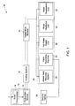
- the hybrid system 10 includes a photovoltaic system 12 having a solar concentrator 14 configured to receive solar energy and further configured to concentrate and guide the solar energy to a photovoltaic module 16.
- the solar concentrator 14 is configured to accept light rays from a broad range of incident flux angles with minimal degradation in performance.
- the solar energy incident on the photovoltaic module 16 is directly transmitted through the above-mentioned solar concentrator 14 or is transmitted by total internal reflection through the solar concentrator 14 or a combination thereof.
- the solar concentrator 14 may include refractive concentrators, reflective concentrators, or combinations thereof.
- the photovoltaic module 16 may include a plurality of photovoltaic cells coupled electrically and may also be embedded in a protective encapsulant (not shown).
- the protective encapsulant is configured to provide strength to the photovoltaic cells and also to protect the photovoltaic cells from extreme ambient conditions.
- the photovoltaic module 16 can achieve higher power densities by focusing sunlight to the photovoltaic module 16 using the solar concentrator 14. In other words, higher concentration of sunlight leads to higher power density. However, increased solar energy concentration leads to heating of the photovoltaic module 16, resulting in increase of temperature of the photovoltaic material.
- An active cooling system 18 is coupled to the photovoltaic module 16 and configured to circulate a cooling fluid through the cooling system 18 so as to remove heat from the photovoltaic module 16 to cool the photovoltaic module 16.
- the cooling fluid includes water.
- the cooling fluid includes water mixed with glycol.
- cooling fluid may include oil or gas.
- a first device 20 is coupled to the cooling system 18 via a temperature booster 22, for example, a solar vacuum tube collector.
- the first device 20 is configured to receive the heated cooling fluid from the cooling system 18 via the temperature booster 22.
- the first device 20 includes a waste heat recovery system 24 configured to generate electric power.
- the waste heat recovery system 24 is configured to remove heat from the heated cooling fluid and generate electric power.
- the first device 20 includes a vapor absorption machine 26 configured to remove heat from the cooling fluid and cool a second device 28.
- the second device 28 may be any application having cooling requirements.
- the first device 20 includes a hot water supply unit 30.
- the first device 20 includes a water distillation unit 32 configured to remove heat from the cooling fluid and distill water.
- the first device 20 includes a water desalination unit 34 configured to remove heat from the cooling fluid and desalinate water.
- the first device 20 includes a combinations thereof of the devices discussed herein.
- the temperature booster 22 is configured to substantially increase the temperature of the heated cooling fluid fed from the cooling system 18 to the first device 20 from a first temperature (for example, 70 degrees Celsius) to a second temperature (for example, 110 degrees Celsius).
- a photovoltaic system is cooled to a relatively low temperature, for example 70 degrees Celsius.
- a cooling fluid at such a lower temperature may not offer other application possibilities.
- the usage of solar booster 22 facilitates to operate the photovoltaic system 12 at low temperature and also boost the temperature of the cooling fluid required for other application possibilities.
- the photovoltaic module 16 includes a plurality of photovoltaic cells 36 coupled to each other electrically.
- the active cooling system 18 is coupled to the photovoltaic module 16 and configured to circulate the cooling fluid through the cooling system 18 so as to remove heat from the photovoltaic module 16 to cool the photovoltaic module 16.
- the cooling system 18 includes an inlet 38 for feeding in the cooling fluid and an outlet for feeding out the cooling fluid. It should be noted herein that the configuration of the cooling system 18 is an exemplary embodiment and should not be construed as limiting.
- the first device 20 is coupled to the cooling system 18 via the temperature booster 22. The first device 20 is configured to receive the heated cooling fluid from the cooling system 18 via the temperature booster 22.
- the active cooling system 18 is coupled to the photovoltaic module 16 and configured to circulate the cooling fluid through the cooling system 18 so as to remove heat from the photovoltaic module 16 to cool the photovoltaic module 16.
- the first device 20 is coupled to the cooling system 18 via the temperature booster 22.
- the first device 20 includes the waste heat recovery system 24 in accordance with an exemplary embodiment of the present invention.
- the illustrated waste heat recovery system 24 is an organic rankine cycle system. It should be noted herein that the waste heat recovery system 24 may be alternatively referred to as the organic rankine cycle system.
- An organic working fluid is circulated through the organic rankine cycle system 24.
- the organic working fluid may include cyclohexane, cyclopentane, thiophene, ketones, aromatics, or combinations thereof.
- the organic rankine cycle system 24 includes an evaporator 42 coupled to the temperature booster 22. The evaporator 42 receives heat from the heated cooling fluid and generates an organic working fluid vapor.
- the organic working fluid vapor is passed through an expander 44 (which in one example comprises a radial type expander) to drive a generator unit 46 for generating electric power.
- the expander 44 may be axial type expander, impulse type expander, or high temperature screw type expander.
- the organic working fluid vapor at a relatively lower pressure and lower temperature is passed through a condenser 48.
- the organic working fluid vapor is condensed into a liquid, which is then pumped via a pump 50 to the evaporator 42. The cycle may then be repeated.
- the illustrated waste heat recovery system 24 includes the organic rankine cycle system.
- the organic rankine cycle system 24 includes the evaporator 42 coupled to the temperature booster 22 via a thermal oil loop 52.
- the evaporator 42 is coupled to the temperature booster 22 via a thermal oil heat exchanger 54.
- the thermal oil heat exchanger 54 is a shell and tube type heat exchanger.
- the thermal oil heat exchanger 54 is used to heat thermal oil to a relatively higher temperature using the heated cooling fluid.
- the evaporator 42 receives heat from the thermal oil and generates the organic working fluid vapor.
- the thermal oil is then pumped back from the evaporator 42 to the thermal oil heat exchanger 54 using a pump 56.
- a heat exchanger 58 is disposed between the expander 44 and the condenser 48 exchanger configured to remove heat from the expanded vaporized working fluid and heat water.
- the hot water may be used for various hot water supply requirements.
- the hybrid system 10 has a thermodynamic cycle coupled to a photovoltaic system to extract electric power from thermal energy. Therefore, the power density from the photovoltaic system 12 can be increased substantially by converting the solar energy to electricity using photovoltaic conversion and converting the excess heat to electrical power using a thermodynamic cycle for waste heat recovery instead of dissipating to the environment. The addition of the thermodynamic cycle for waste heat recovery facilitates cooling of the photovoltaic system 12 and generating additional carbon-dioxide-free electricity.
- a curve 60 represents variation in power generated by the photovoltaic system with respect to temperature.
- a curve 62 represents variation in power generated by the waste heat recovery system with respect to temperature.
- a curve 64 represents variation in combined power output from the exemplary hybrid system with respect to temperature.
- the curve 60 indicates that the power output from the photovoltaic system decreases with increase in temperature.
- the curve 62 indicates that the power output from the waste heat recovery system increases with increase in temperature.
- the curve 64 indicates that the combined power output from the hybrid system increases with respect to temperature up to a predetermined temperature point 66 and is then saturated as the temperature increases beyond the temperature point 66.
- the power output from the hybrid system is saturated beyond the temperature point 66 as the increase in power output from the waste heat recovery system compensates the decrease in power output from the photovoltaic system.
- a curve 68 represents variation in effective electric efficiency with respect to temperature. The curve 68 indicates that the effective electric efficiency of the hybrid system increases upto a predetermined temperature point 70 and then gets saturated beyond the predetermined temperature point 70.
- a curve 72 represents variation in electric power output from the waste heat recovery system with respect to temperature.
- a curve 74 represents variation in electric power output from the photovoltaic system with respect to temperature.
- a curve 76 represents variation in combined electric power output from the hybrid system with respect to temperature.
- the power output from the photovoltaic system decreases with increase in temperature.
- the power output from the waste heat recovery system increases with increase in temperature.
- the combined power output from the hybrid system increases with respect to temperature.
- the hybrid system may have a power density of 700 watts per meter squared.
- FIG. 8 a graphical representation of combined electric efficiency of the hybrid system (expressed in percentage) versus temperature (expresses in degrees Celsius) is illustrated.
- the curve 78 indicates that the effective efficiency of the hybrid system increases with increase in temperature.
- the photovoltaic system 12 is combined with the vapor absorption machine 26.
- the vapor absorption machine 26 is a heated cooling fluid driven vapor absorption machine 26.
- the vapor absorption machine 26 may be driven using hot water fed through the temperature booster 22.
- the machine 26 is used for cooling or air conditioning of the second device 28.
- the photovoltaic system 12 is combined with the hot water supply unit 30.
- the supply unit 30 is configured to feed the hot water fed through the temperature booster 22.
- the photovoltaic system 12 is combined with the water distillation unit 32.
- the distillation unit 32 is used to remove thermal energy from the heated cooling fluid fed through the booster 22 and distill water.
- the photovoltaic system 12 is combined with the water desalination unit 34.
- the desalination unit 34 is used to remove thermal energy from the heated cooling fluid fed through the booster 22 and desalinate water.
- the waste heat recovery system 24, the vapor absorption machine 26, the hot water supply unit 30, the water distillation unit 32, and the water desalination unit 34 are selectively activated and deactivated based on a plurality of parameters temperature and pressure of the cooling fluid, solar irradiance on the photovoltaic system 12, efficiency of the waste heat recovery system 24 versus temperature of a working fluid distributed through the waste heat recovery system 24, coefficient of performance of the vapor absorption machine 26 versus temperature of a fluid circulated through the vapor absorption machine 26, cost of electric power, cooling load of the photovoltaic system 12, requirement of hot water through the hot water supply unit 30, cost of thermal energy of the heated cooling fluid, or combinations thereof.
- a control system embedded with a decision making algorithm may be used to determine whether the thermal energy or heat of the cooling fluid may be used for electricity generation, hot water, cooling purpose, or the like.
- the algorithm is used to determine the optimal use of the thermal energy of the cooling fluid based on the plurality of parameters mentioned above.
- the hybrid system 10 provides substantially higher power density, lower cost per unit of power, multi-power generation i.e. electricity, heat, cooling purposes.
Landscapes
- Photovoltaic Devices (AREA)
- Heat Treatment Of Water, Waste Water Or Sewage (AREA)
Applications Claiming Priority (1)
| Application Number | Priority Date | Filing Date | Title |
|---|---|---|---|
| US12/818,384 US20110308576A1 (en) | 2010-06-18 | 2010-06-18 | Hybrid photovoltaic system and method thereof |
Publications (1)
| Publication Number | Publication Date |
|---|---|
| EP2398070A2 true EP2398070A2 (fr) | 2011-12-21 |
Family
ID=44720529
Family Applications (1)
| Application Number | Title | Priority Date | Filing Date |
|---|---|---|---|
| EP11169120A Withdrawn EP2398070A2 (fr) | 2010-06-18 | 2011-06-08 | Système photovoltaïque hybride et son procédé |
Country Status (4)
| Country | Link |
|---|---|
| US (1) | US20110308576A1 (fr) |
| EP (1) | EP2398070A2 (fr) |
| CN (1) | CN102315797A (fr) |
| AU (1) | AU2011202685A1 (fr) |
Cited By (1)
| Publication number | Priority date | Publication date | Assignee | Title |
|---|---|---|---|---|
| WO2013182716A1 (fr) * | 2012-06-04 | 2013-12-12 | Investigaciones, Desarrollos E Innovaciones Tat Iberica, S.L. | Système modulaire pour la capture d'énergie solaire photovoltaïque |
Families Citing this family (8)
| Publication number | Priority date | Publication date | Assignee | Title |
|---|---|---|---|---|
| US9278315B2 (en) * | 2010-10-11 | 2016-03-08 | Board Of Regents, The University Of Texas System | Photovoltaic-thermal (PV-T) system for desalination |
| US9353974B2 (en) | 2012-04-30 | 2016-05-31 | Daniel Demers | Solar collecting device |
| US10066856B2 (en) * | 2015-11-17 | 2018-09-04 | King Fahd University Of Petroleum And Minerals | Integrated solar absorption heat pump system |
| CN107381696A (zh) * | 2017-07-20 | 2017-11-24 | 林启乐 | 一种半导体制冷的多层次混合缓冲太阳能光伏蒸馏器 |
| CA3165230C (fr) * | 2019-12-30 | 2025-07-22 | Matterport, Inc. | Systeme et procede de capture et de generation d'images panoramiques tridimensionnelles |
| US11761644B1 (en) | 2022-04-25 | 2023-09-19 | King Fahd University Of Petroleum And Minerals | Cooling and desalination system |
| CN116307237B (zh) * | 2023-03-31 | 2024-10-25 | 西北工业大学 | 基于盐差能和光伏混合系统能效的优化方法及系统 |
| CN117833769B (zh) * | 2023-12-25 | 2024-08-06 | 中国华电科工集团有限公司 | 一种光伏光热耦合冷能发电系统及其运行方法 |
Family Cites Families (20)
| Publication number | Priority date | Publication date | Assignee | Title |
|---|---|---|---|---|
| US4358929A (en) * | 1974-04-02 | 1982-11-16 | Stephen Molivadas | Solar power system |
| US4002031A (en) * | 1975-07-07 | 1977-01-11 | Varian Associates, Inc. | Solar energy converter with waste heat engine |
| JPS62206302A (ja) * | 1986-03-05 | 1987-09-10 | 株式会社 日阪製作所 | 蒸発装置 |
| TW401647B (en) * | 1996-06-19 | 2000-08-11 | Ebara Corp | Desalting apparatus and method for operating such process |
| US6000211A (en) * | 1997-06-18 | 1999-12-14 | York Research Corporation | Solar power enhanced combustion turbine power plant and methods |
| US7296410B2 (en) * | 2003-12-10 | 2007-11-20 | United Technologies Corporation | Solar power system and method for power generation |
| US20050269211A1 (en) * | 2004-06-07 | 2005-12-08 | Zachar Oron D | Method of and apparatus for producing hydrogen using geothermal energy |
| US7428816B2 (en) * | 2004-07-16 | 2008-09-30 | Honeywell International Inc. | Working fluids for thermal energy conversion of waste heat from fuel cells using Rankine cycle systems |
| EP1705242A1 (fr) * | 2005-03-23 | 2006-09-27 | KRONES Aktiengesellschaft | Installation de brasserie et procédé de brassage |
| CN101248253B (zh) * | 2005-03-29 | 2010-12-29 | Utc电力公司 | 利用废热的级联有机兰金循环 |
| US20070157922A1 (en) * | 2005-12-29 | 2007-07-12 | United Technologies Corporation | Integrated electrical and thermal energy solar cell system |
| US7594399B2 (en) * | 2006-12-13 | 2009-09-29 | General Electric Company | System and method for power generation in Rankine cycle |
| WO2008114248A1 (fr) * | 2007-03-16 | 2008-09-25 | T.O.U Millennium Electric Ltd. | Génération d'énergie thermique solaire combinée et station énergétique prévue à cet effet |
| US8132409B2 (en) * | 2007-05-08 | 2012-03-13 | Solar Turbine Group, International | Solar collection and conversion system and methods and apparatus for control thereof |
| US8561405B2 (en) * | 2007-06-29 | 2013-10-22 | General Electric Company | System and method for recovering waste heat |
| CN101451748A (zh) * | 2007-11-30 | 2009-06-10 | 上海极特实业有限公司 | 利用燃气和电能补偿的太阳能节能系统及方法 |
| CN102056847B (zh) * | 2008-04-15 | 2013-06-05 | 联合太阳能科技有限公司 | 水回收系统和方法 |
| US20100031953A1 (en) * | 2008-08-07 | 2010-02-11 | Krassimire Mihaylov Penev | Hybrid Water Heating System |
| WO2010080549A1 (fr) * | 2008-12-17 | 2010-07-15 | Hulen Michael S | Systèmes et procédés pour faire fonctionner un équipement environnemental utilisant de l'énergie obtenue à partir de couvertures de surface manufacturées présentant des améliorations en termes d'efficacité |
| EP2436041A2 (fr) * | 2009-05-26 | 2012-04-04 | Cogenra Solar, Inc. | Système photovoltaïque-thermique solaire à concentration |
-
2010
- 2010-06-18 US US12/818,384 patent/US20110308576A1/en not_active Abandoned
-
2011
- 2011-06-06 AU AU2011202685A patent/AU2011202685A1/en not_active Abandoned
- 2011-06-08 EP EP11169120A patent/EP2398070A2/fr not_active Withdrawn
- 2011-06-17 CN CN2011101754727A patent/CN102315797A/zh active Pending
Non-Patent Citations (1)
| Title |
|---|
| None |
Cited By (1)
| Publication number | Priority date | Publication date | Assignee | Title |
|---|---|---|---|---|
| WO2013182716A1 (fr) * | 2012-06-04 | 2013-12-12 | Investigaciones, Desarrollos E Innovaciones Tat Iberica, S.L. | Système modulaire pour la capture d'énergie solaire photovoltaïque |
Also Published As
| Publication number | Publication date |
|---|---|
| CN102315797A (zh) | 2012-01-11 |
| US20110308576A1 (en) | 2011-12-22 |
| AU2011202685A1 (en) | 2012-01-19 |
Similar Documents
| Publication | Publication Date | Title |
|---|---|---|
| EP2398070A2 (fr) | Système photovoltaïque hybride et son procédé | |
| Kamel et al. | Solar systems and their integration with heat pumps: A review | |
| Han et al. | Parametric analysis of a hybrid solar concentrating photovoltaic/concentrating solar power (CPV/CSP) system | |
| KR101109535B1 (ko) | 태양 에너지를 이용한 증발식 해수담수화 시스템 | |
| AU2018204506B2 (en) | Storage of solar energy | |
| US9705449B2 (en) | Effective and scalable solar energy collection and storage | |
| RU2012111666A (ru) | Увеличение эффективности преобразующих систем для преобразования океанической тепловой энергии с дополнительными средствами | |
| CN103607166B (zh) | 一种聚光光伏光热复合发电系统 | |
| Han et al. | Energy analysis of a hybrid solar concentrating photovoltaic/concentrating solar power (CPV/CSP) system | |
| CN104807205B (zh) | 光伏、光热和介质储热联合供能系统 | |
| KR20100007240A (ko) | 공기집열식 태양광발전장치 | |
| CN106160630B (zh) | 一种光伏光热综合利用发电装置 | |
| Desai et al. | Techno-economic analysis of a foil-based solar collector driven electricity and fresh water generation system | |
| US20120273026A1 (en) | Hybrid solar concentration device | |
| CN102937073B (zh) | 一种无蓄电池式昼夜光伏水泵系统 | |
| SA112330172B1 (ar) | طريقة ومجموعة لتحويل إشعاع شمسي في قدرة ميكانيكية ، تحديدًا وبدون حصر لتوليد قدرة كهربائية | |
| Hao et al. | Performance investigation of a concentrated photovoltaics-phase change material-thermoelectric generator system based on topology optimization | |
| CN102168661B (zh) | 复合能源太阳能高温热发电系统 | |
| JP6138495B2 (ja) | 発電システム | |
| CN202348595U (zh) | 太阳光热电槽式发电站系统 | |
| KR101017891B1 (ko) | 태양에너지를 이용한 열병합발전장치 | |
| CN215909457U (zh) | 一种高效光伏发电系统 | |
| CN103423109B (zh) | 一种利用太阳能和地热能的联合发电装置 | |
| KR20150086279A (ko) | 전력 생성을 위한 하이브리드 조합 사이클 시스템 | |
| Babu et al. | Performance analysis of flat plate hybrid PV/thermal configurations |
Legal Events
| Date | Code | Title | Description |
|---|---|---|---|
| AK | Designated contracting states |
Kind code of ref document: A2 Designated state(s): AL AT BE BG CH CY CZ DE DK EE ES FI FR GB GR HR HU IE IS IT LI LT LU LV MC MK MT NL NO PL PT RO RS SE SI SK SM TR |
|
| AX | Request for extension of the european patent |
Extension state: BA ME |
|
| PUAI | Public reference made under article 153(3) epc to a published international application that has entered the european phase |
Free format text: ORIGINAL CODE: 0009012 |
|
| STAA | Information on the status of an ep patent application or granted ep patent |
Free format text: STATUS: THE APPLICATION IS DEEMED TO BE WITHDRAWN |
|
| 18D | Application deemed to be withdrawn |
Effective date: 20140103 |