EP2398109A1 - Echangeur de chaleur et procédé de fabrication d'un échangeur de chaleur - Google Patents
Echangeur de chaleur et procédé de fabrication d'un échangeur de chaleur Download PDFInfo
- Publication number
- EP2398109A1 EP2398109A1 EP20110170132 EP11170132A EP2398109A1 EP 2398109 A1 EP2398109 A1 EP 2398109A1 EP 20110170132 EP20110170132 EP 20110170132 EP 11170132 A EP11170132 A EP 11170132A EP 2398109 A1 EP2398109 A1 EP 2398109A1
- Authority
- EP
- European Patent Office
- Prior art keywords
- opening
- heat exchanger
- energy storage
- profile
- housing surface
- Prior art date
- Legal status (The legal status is an assumption and is not a legal conclusion. Google has not performed a legal analysis and makes no representation as to the accuracy of the status listed.)
- Withdrawn
Links
- 238000004519 manufacturing process Methods 0.000 title claims abstract description 8
- 238000000034 method Methods 0.000 title description 9
- 238000001816 cooling Methods 0.000 claims abstract description 39
- 238000004146 energy storage Methods 0.000 claims description 64
- 210000000352 storage cell Anatomy 0.000 claims description 59
- 239000012530 fluid Substances 0.000 claims description 21
- 230000002093 peripheral effect Effects 0.000 claims description 14
- 229910052751 metal Inorganic materials 0.000 claims description 6
- 239000002184 metal Substances 0.000 claims description 6
- 238000007599 discharging Methods 0.000 claims description 3
- 238000003860 storage Methods 0.000 claims description 2
- HBBGRARXTFLTSG-UHFFFAOYSA-N Lithium ion Chemical compound [Li+] HBBGRARXTFLTSG-UHFFFAOYSA-N 0.000 abstract description 4
- 229910001416 lithium ion Inorganic materials 0.000 abstract description 4
- 210000004027 cell Anatomy 0.000 description 45
- 238000002788 crimping Methods 0.000 description 5
- 238000012546 transfer Methods 0.000 description 5
- 229910052782 aluminium Inorganic materials 0.000 description 4
- XAGFODPZIPBFFR-UHFFFAOYSA-N aluminium Chemical compound [Al] XAGFODPZIPBFFR-UHFFFAOYSA-N 0.000 description 4
- 238000013461 design Methods 0.000 description 4
- 230000008569 process Effects 0.000 description 4
- 239000002826 coolant Substances 0.000 description 3
- 238000003466 welding Methods 0.000 description 3
- 238000010276 construction Methods 0.000 description 2
- 230000017525 heat dissipation Effects 0.000 description 2
- 238000003780 insertion Methods 0.000 description 2
- 230000037431 insertion Effects 0.000 description 2
- 238000005304 joining Methods 0.000 description 2
- 239000000463 material Substances 0.000 description 2
- 239000011159 matrix material Substances 0.000 description 2
- 238000005476 soldering Methods 0.000 description 2
- 230000009471 action Effects 0.000 description 1
- 238000004026 adhesive bonding Methods 0.000 description 1
- 238000013459 approach Methods 0.000 description 1
- 238000005452 bending Methods 0.000 description 1
- 230000008901 benefit Effects 0.000 description 1
- 239000012809 cooling fluid Substances 0.000 description 1
- 230000005489 elastic deformation Effects 0.000 description 1
- 238000005516 engineering process Methods 0.000 description 1
- 239000011888 foil Substances 0.000 description 1
- 230000006870 function Effects 0.000 description 1
- 238000009434 installation Methods 0.000 description 1
- 230000009191 jumping Effects 0.000 description 1
- 239000000047 product Substances 0.000 description 1
- 230000003252 repetitive effect Effects 0.000 description 1
- 239000011265 semifinished product Substances 0.000 description 1
- 239000000126 substance Substances 0.000 description 1
- 230000010512 thermal transition Effects 0.000 description 1
- 239000013585 weight reducing agent Substances 0.000 description 1
Images


Classifications
-
- F—MECHANICAL ENGINEERING; LIGHTING; HEATING; WEAPONS; BLASTING
- F28—HEAT EXCHANGE IN GENERAL
- F28F—DETAILS OF HEAT-EXCHANGE AND HEAT-TRANSFER APPARATUS, OF GENERAL APPLICATION
- F28F3/00—Plate-like or laminated elements; Assemblies of plate-like or laminated elements
- F28F3/12—Elements constructed in the shape of a hollow panel, e.g. with channels
-
- F—MECHANICAL ENGINEERING; LIGHTING; HEATING; WEAPONS; BLASTING
- F28—HEAT EXCHANGE IN GENERAL
- F28F—DETAILS OF HEAT-EXCHANGE AND HEAT-TRANSFER APPARATUS, OF GENERAL APPLICATION
- F28F21/00—Constructions of heat-exchange apparatus characterised by the selection of particular materials
- F28F21/06—Constructions of heat-exchange apparatus characterised by the selection of particular materials of plastics material
- F28F21/065—Constructions of heat-exchange apparatus characterised by the selection of particular materials of plastics material the heat-exchange apparatus employing plate-like or laminated conduits
-
- H—ELECTRICITY
- H01—ELECTRIC ELEMENTS
- H01M—PROCESSES OR MEANS, e.g. BATTERIES, FOR THE DIRECT CONVERSION OF CHEMICAL ENERGY INTO ELECTRICAL ENERGY
- H01M10/00—Secondary cells; Manufacture thereof
- H01M10/60—Heating or cooling; Temperature control
- H01M10/61—Types of temperature control
- H01M10/613—Cooling or keeping cold
-
- H—ELECTRICITY
- H01—ELECTRIC ELEMENTS
- H01M—PROCESSES OR MEANS, e.g. BATTERIES, FOR THE DIRECT CONVERSION OF CHEMICAL ENERGY INTO ELECTRICAL ENERGY
- H01M10/00—Secondary cells; Manufacture thereof
- H01M10/60—Heating or cooling; Temperature control
- H01M10/64—Heating or cooling; Temperature control characterised by the shape of the cells
- H01M10/643—Cylindrical cells
-
- H—ELECTRICITY
- H01—ELECTRIC ELEMENTS
- H01M—PROCESSES OR MEANS, e.g. BATTERIES, FOR THE DIRECT CONVERSION OF CHEMICAL ENERGY INTO ELECTRICAL ENERGY
- H01M10/00—Secondary cells; Manufacture thereof
- H01M10/60—Heating or cooling; Temperature control
- H01M10/64—Heating or cooling; Temperature control characterised by the shape of the cells
- H01M10/647—Prismatic or flat cells, e.g. pouch cells
-
- H—ELECTRICITY
- H01—ELECTRIC ELEMENTS
- H01M—PROCESSES OR MEANS, e.g. BATTERIES, FOR THE DIRECT CONVERSION OF CHEMICAL ENERGY INTO ELECTRICAL ENERGY
- H01M10/00—Secondary cells; Manufacture thereof
- H01M10/60—Heating or cooling; Temperature control
- H01M10/65—Means for temperature control structurally associated with the cells
- H01M10/655—Solid structures for heat exchange or heat conduction
- H01M10/6554—Rods or plates
-
- H—ELECTRICITY
- H01—ELECTRIC ELEMENTS
- H01M—PROCESSES OR MEANS, e.g. BATTERIES, FOR THE DIRECT CONVERSION OF CHEMICAL ENERGY INTO ELECTRICAL ENERGY
- H01M10/00—Secondary cells; Manufacture thereof
- H01M10/60—Heating or cooling; Temperature control
- H01M10/65—Means for temperature control structurally associated with the cells
- H01M10/655—Solid structures for heat exchange or heat conduction
- H01M10/6556—Solid parts with flow channel passages or pipes for heat exchange
-
- F—MECHANICAL ENGINEERING; LIGHTING; HEATING; WEAPONS; BLASTING
- F28—HEAT EXCHANGE IN GENERAL
- F28F—DETAILS OF HEAT-EXCHANGE AND HEAT-TRANSFER APPARATUS, OF GENERAL APPLICATION
- F28F3/00—Plate-like or laminated elements; Assemblies of plate-like or laminated elements
- F28F3/08—Elements constructed for building-up into stacks, e.g. capable of being taken apart for cleaning
- F28F3/086—Elements constructed for building-up into stacks, e.g. capable of being taken apart for cleaning having one or more openings therein forming tubular heat-exchange passages
-
- H—ELECTRICITY
- H01—ELECTRIC ELEMENTS
- H01M—PROCESSES OR MEANS, e.g. BATTERIES, FOR THE DIRECT CONVERSION OF CHEMICAL ENERGY INTO ELECTRICAL ENERGY
- H01M10/00—Secondary cells; Manufacture thereof
- H01M10/60—Heating or cooling; Temperature control
- H01M10/62—Heating or cooling; Temperature control specially adapted for specific applications
- H01M10/625—Vehicles
-
- Y—GENERAL TAGGING OF NEW TECHNOLOGICAL DEVELOPMENTS; GENERAL TAGGING OF CROSS-SECTIONAL TECHNOLOGIES SPANNING OVER SEVERAL SECTIONS OF THE IPC; TECHNICAL SUBJECTS COVERED BY FORMER USPC CROSS-REFERENCE ART COLLECTIONS [XRACs] AND DIGESTS
- Y02—TECHNOLOGIES OR APPLICATIONS FOR MITIGATION OR ADAPTATION AGAINST CLIMATE CHANGE
- Y02E—REDUCTION OF GREENHOUSE GAS [GHG] EMISSIONS, RELATED TO ENERGY GENERATION, TRANSMISSION OR DISTRIBUTION
- Y02E60/00—Enabling technologies; Technologies with a potential or indirect contribution to GHG emissions mitigation
- Y02E60/10—Energy storage using batteries
Definitions
- the present invention relates to a heat exchanger and to a method for producing a heat exchanger, which can be used, for example, for cooling energy storage cells.
- the cells can be pushed into fixed insertion pockets between the coolant-filled "spikes" of the cooling gel and fixed.
- Thedeigel is very massive and therefore very heavy. Furthermore, the pockets have a slight excess for reasons of process reliability. Due to this necessary tolerance, the heat transfer based on thermal contact deteriorates significantly.
- the cells can be placed on a traversed with coolant channels cooling plate and fixed separately.
- the cells are cooled only at the bottom of the hard case.
- This one-sided cooling leads to high temperature differences within the cell.
- the embodiments of the cooling plate with and without cooling plates are heavy due to the high weight of the cooling plate and require additional fastening and bracing elements. A weight reduction by omitting the bracing elements would lead to a significantly reduced heat transfer and thus reduce the effectiveness of the cooling.
- cooling plate with cooling plates thin-walled L or T-profiles are clamped on a traversed with coolant channels cooling plate, which transport the cooling capacity of the cooling plate to the cells, which are in the "sandwich" of the cooling plates. It can be significantly reduced by an optimized design of the cooling plates, the temperature difference in the cell compared to the embodiment without a cooling plate. However, the weight increases significantly due to the cooling plates and the increased effort for fixing and clamping of metal sheets and cells. Also, two thermal contact-based interfaces are needed for this solution. In thedeigel and the embodiment without cooling plate only one is needed. Thermal contacts always place increased demands on tolerance, surface quality and rigidity in order to ensure a good thermal transition coefficient.
- the present invention is based on the finding that curved shaft profiles are suitable for thermally connecting energy cells with a heat exchanger.
- a slide-in cooler based on curved manhole profiles can be created.
- the slide-in cooler is suitable as a cooler for cooling energy storage systems.
- the energy storage cells are plugged into the cooler.
- the shaft profiles press against the cells and thus form a heat transfer to the cell.
- the result is a simple and lightweight design for the cooling components of cells while ensuring effective and safe cooling.
- the construction either contains all the functions relating to connection and clamping of the cooling component and cells directly, or at least allows simple solutions.
- the construction according to the invention is very compact and enables effective cooling of prismatic cells with metal housing.
- the good efficiency is achieved by the fact that the only thermal interface between shaft profile and cell housing by the constraint of the elastically deformed shaft profile has a very good heat transfer.
- the position of the cooling via the cell height can be set variably or even supplemented by an additional bottom cooling of the cells.
- Another advantage is the closed solution, as it is just a product that can be mounted without any special parts or tools in any environment. Access to the cells is not hampered by the modular design. Single cells can be easily exchanged.
- the heat exchanger according to the invention can be used for small-sized energy storage, for example based on lithium ions.
- the amount of heat continuously generated due to the power loss during charging or discharging inside the cell, which corresponds to the power loss of the cell, can be dissipated via the shaft profiles with the same speed. It can be ensured that the temperature difference within a cell and within a module does not exceed a cell-specific value.
- the approach of the present invention provides an optimized method for cooling "hard" cell cells, typically prismatic or cylindrical cells with aluminum housings.
- the present invention provides a heat exchanger for cooling at least one energy storage cell, having the following features: a first housing surface having at least one first opening; a second housing surface having at least a second opening, wherein the second housing surface of the first housing surface and the second opening of the first opening is arranged opposite; and at least one well profile connected to a peripheral edge region of the first opening and having a peripheral edge region of the second opening and extending between the first and the second housing surface to form a wall of a storage slot for an energy storage cell, the well profile in a between the first and the second housing surface lying region has an elastic curvature in the direction of an interior of the receiving shaft.
- the energy storage cell may be a galvanic element.
- the energy storage cell can be used for example in an electric vehicle or a hybrid vehicle.
- the heat exchanger has a housing, in which the first housing surface and the second housing surface are arranged opposite one another.
- the housing has one or a plurality of receiving wells which form through holes through the housing.
- Each of the receiving wells is formed by a first opening, a second opening and a manhole profile.
- the receiving wells form pillars between the first and second housing surfaces.
- the shaft profile may be made of a different material than the housing surfaces and have been subsequently connected to this. For this purpose, the shaft profile may have been connected to the openings, for example, in each case by means of a cohesive or a positive connection technology.
- the openings may be adapted in their cross-sectional area to a cross-sectional area of the energy source to be absorbed.
- the openings may have a round cross section or a rectangular cross section.
- a cross-sectional area of the manhole profile can be adapted to the cross-sectional area of the openings.
- Each of the receiving wells is configured to receive one or more energy storage cells.
- the energy storage cell can be introduced into the receiving shaft and shoot down flush with the first housing surface and the second housing surface or protrude beyond the first, the second or both housing surfaces.
- the housing may have further housing surfaces, which adjoin the first housing surface and the second housing surface to close the housing to the outside.
- the elastic curvature can extend over a partial area or over an entire length of the manhole profile.
- an energy storage cell If an energy storage cell is arranged in a receiving shaft, it presses with its side surface against the elastic curvature and deforms it. The deformation of the elastic curvature produces a restoring force with which the elastic curvature presses against the side surface of the energy storage cell. As a result, the energy storage cell is mechanically fixed in the receiving shaft. In addition, a contact surface is formed between the elastic curvature and the side surface of the energy storage cell, via which there is a thermally conductive connection between the heat exchanger and the energy storage cell.
- an inner diameter of the receiving shaft in the region of the elastic curvature can be smaller than a corresponding outer diameter of the energy storage cell.
- the elastic curvature can exert a holding force on the energy storage cell and form a thermal connection to the energy storage cell when the energy storage cell is arranged in the receiving shaft.
- the corresponding outer diameter is an outer diameter of the energy storage cell in the region opposite to the elastic curvature when the energy storage cell is arranged in the receiving well.
- the area where the inside diameter of the receiving shaft is smaller than the corresponding outer diameter of the energy storage cell for example, may extend over a third, half or two-thirds of the length of the receiving shaft. This area can be arranged centrally with respect to the length of the receiving shaft.
- the at least one shaft profile can be bent continuously in the region lying between the first and the second housing surface in order to form the elastic curvature.
- the elastic curvature can be generated by a deformation of the manhole profile, which results from the rigid connection of the manhole profile with the openings.
- the shaft profile may be bent before the connection with the openings.
- the at least one shaft profile is connected to the peripheral edge regions of the at least one first opening and the at least one second opening in a continuous and fluid-tight manner. This makes it possible that a gap between the housing surfaces is flowed through by a fluid. As a result, the heat dissipation via the shaft profiles can be increased.
- the heat exchanger may have a first fluid port for supplying a fluid and a second fluid port for discharging the fluid.
- the fluid connections can be arranged so that the fluid can flow around the wall of the at least one receiving shaft in a region between the first and the second housing surface.
- the heat exchanger can be connected to a cooling circuit.
- the housing surfaces may be made of plastic and the at least one shaft profile may be made of metal.
- the plastic can save weight.
- the metal offers a high thermal conductivity.
- the at least one shaft profile may be a tube. Depending on the cross-sectional area of the energy source, this may be a round tube or a flat tube.
- the at least one shaft profile can be composed of several separate profile sections.
- the heat exchanger can have a number of first openings, a number of second openings corresponding to the number of first openings and a number of shaft profiles corresponding to the number of first openings, around a number of receiving shafts corresponding to the number of first openings for a number of energy storage cells corresponding to the number of first openings to build.
- the receiving wells may be evenly distributed over the housing surfaces, for example, the receiving wells may be arranged in a plurality of rows and a plurality of columns, wherein adjacent receiving wells may be arranged offset from one another. A distance between two adjacent receiving wells can be chosen so that on the one hand optimal heat dissipation is ensured and on the other hand the largest possible number of energy storage cells can be arranged on the smallest possible area.
- the heat exchanger according to the invention may comprise the at least one energy storage cell.
- the energy storage cell can be arranged in the receiving shaft and held in position by the elastic curvature. Thus, a complete energy storage system is created.
- the energy storage cell may include a bracket extending along opposite side surfaces of the effusion memory cell. Thus, a part of the bracket between the side surfaces of the energy storage cell and the wall of the receiving shaft can be located.
- the clip may allow additional fixation of the energy storage cell in the receiving shaft.
- the clip may for example have hooks.
- the present invention further provides a method for producing a heat exchanger for cooling at least one energy storage cell, which the comprising the steps of: providing a housing having a first housing surface having at least a first opening and a second housing surface having at least a second opening wöbei the second housing surface of the first housing surface, and the second opening of the first opening opposite one another; Inserting a well profile into the at least one first and at least one second opening so that the well profile extends between the first and second casing surfaces to form a wall of a receptacle for an energy storage cell, wherein a diameter of each of the first and second openings is larger is an outer diameter of the well profile such that a peripheral edge region of the first opening and a peripheral edge region of the second opening is at least partially spaced from the well profile; and continuous connection of the manhole profile with the peripheral edge region of the first opening and the peripheral edge region of the second opening, so that the manhole profile has an elastic curvature in the direction of an interior of the receiving shaft in a region lying between the first and
- the elastic curvature can be generated by connecting the manhole profile with the housing surfaces, so that no pre-bending for the manhole profile is required.
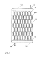
- Fig. 1 shows a representation of a heat exchanger according to the invention from above, according to an embodiment of the present invention.
- the Heat exchanger has a housing from which in the in Fig. 1 shown a first housing surface 102 is shown.
- the first housing surface 102 has a plurality of first openings 104, of which only one opening is provided with a reference numeral 104 for the sake of clarity.
- Each of the first openings 104 is each part of a receiving slot for receiving an energy storage cell.
- the first openings 104 have a rectangular cross-sectional area.
- the first openings 104 are arranged in a plurality of columns and in a plurality of rows.
- the first openings 104 are arranged in seven columns, which each have 12 and 13 openings 104 alternately.
- the first openings 104 are offset relative to one another with respect to adjacent columns.
- the heat exchanger has two collectors 108 arranged at opposite ends of the heat exchanger.
- the collectors 106 form containers which each have a fluid connection 108.
- Fig. 2 shows a front view of the in Fig. 1 shown heat exchanger. Shown are an arrangement of the first housing surface 102 and an opposite second housing surface 202. The first housing surface 102 and the second housing surface 202 are arranged parallel and spaced from one another. In each case an energy storage cell 220 is arranged in the receiving shafts of the heat exchanger, of which only one is provided with a reference numeral 220 for the sake of clarity. According to this embodiment, the energy storage cells 220 protrude beyond the first housing surface 102 and the second housing surface 202, respectively.
- the heat exchanger is arranged approximately centrally with respect to a height of the energy storage cells 220.
- Fig. 3 shows a side view of the in Fig. 1
- an energy storage cell 220 is arranged, of which only one is provided with a reference numeral for the sake of clarity.
- the energy storage cells 220 protrude beyond the first housing surface 102 and the second housing surface 202, respectively.
- the heat exchanger is arranged approximately centrally with respect to a height of the energy storage cells 220.
- a section 330 is in Fig. 4 shown enlarged
- Fig. 4 shows the cutout 330 Fig. 3 , Shown is a side view of the heat exchanger with an energy storage cell 220.
- the energy storage cell 220 is disposed in a receiving shaft of the heat exchanger.
- the receiving shaft is formed by two opposing openings or passages in the first housing surface 102 and the second housing surface 202.
- the passages may correspond to the wall of the housing surfaces 102, 202 in the region of the openings.
- the openings of the housing surfaces 102, 202 are connected via a shaft profile 435.
- the edge regions of the housing surfaces 102, 202 are bent outward.
- the shaft profile 435 is connected to the housing surfaces 102, 202 at the edge regions.
- the shaft profile 435 has a bulge into the interior of the shaft profile 435.
- the manhole profile 435 has a larger cross-sectional area at the edge regions than therebetween.
- the smallest cross-sectional area has the well profile 435 approximately midway between the first and second housing surfaces 102, 202.
- the energy storage cell 220 points along the in Fig. 4 shown narrow side to a larger diameter than the shaft profile 435 in the region of the smallest cross-sectional area.
- the cell 220 has an oversize.
- a thermal contact under pressure arises between the side surfaces of the cell 220 and the well profile 435.
- the energy storage cell 220 has brackets 437 or the like.
- Fig. 5 shows the cutout 330 Fig. 3 in a front view. Shown is a section of the heat exchanger with an energy storage cell 220.
- the energy storage cell 220 is arranged in a receiving shaft of the heat exchanger.
- the receiving shaft is like in Fig. 4 described trained.
- the cell 220 points along the in Fig. 5 shown broad side on a smaller cross section than the shaft profile at its narrowest point. Thus, the cell 220 is undersized.
- brackets or snap hooks are provided.
- a clip 437 is attached to an upper side of the energy storage cell 220 and extends along the energy storage cell 220 on both sides.
- the clip 437 has outwardly bent hooks at end sections, which hook onto the edge regions of the opening in the second housing surface 202.
- Fig. 6 shows a cross-sectional view of the housing (cooler can) of in Fig. 1 shown with the first and second housing surface 102, 202.
- the housing may for example consist of plastic.
- Fig. 7 shows a cross-sectional view of a distributor 110 (header) of the in Fig. 1 shown heat exchanger.
- the distributor 110 has a plurality of openings, the cross-section of which increases the farther they are from the inlet opening of the fluid.
- the distributor 110 may be made of plastic, for example.
- Fig. 8 shows one of a collector 106 (tank) of a erfindungsgerna built heat exchanger with the inlet opening 108 for the fluid.
- Fig. 9 shows the cutout 330 Fig. 3 without energy storage cell. Shown is a side view of a receiving shaft of the heat exchanger.
- the receiving shaft is formed by two opposite openings or passages in the first housing surface 102 and the second housing surface 202, which are connected via a shaft profile 435, the shaft profile 435 (cell slot chamber profile) may for example consist of aluminum.
- a section 940 is in Fig. 12 shown enlarged
- Fig. 10 shows the cutout 330 Fig. 3 Shown is a width a of the housing of the cell 220 and a minimum width az of the receiving shaft.
- An overlap z may vary over a circumference of the absorptive shaft, for example, between the front view and the side view.
- the receiving shaft may have at its narrowest point, for example, a smaller diameter than the narrow side, however, a larger diameter than the broad side of the energy storage cell
- Fig. 11 shows the cutout 330 Fig. 3 in a front view, without an energy storage cell.
- a cooler housing formed by the housing surfaces 102, 202 may be made of plastic, for example.
- Fig. 12 shows an enlarged view of the in the Figures 9 and 11 Shown is the first housing surface 102 of the cooler housing, which may for example consist of plastic, and the shaft profile 435.
- the shaft profile 435 may be designed as a tube, for example made of aluminum.
- crimping 1253 creates a fluid-tight connection.
- the fluid-tight connection can be made in addition to folding, for example, by soldering, welding or other joining techniques.
- the fluid-tight connection can be created by positive or non-positive connection or by a thermal or chemical joining process.
- the heat exchanger according to an embodiment of the invention will be described in detail.
- the shaft profiles 435 which are in direct contact with the cells 220.
- the shaft profiles 435 can be, for example, thin-walled tubes in a flat or round design. These are pushed through a cooler housing 102, 202 made of plastic into openings provided for this purpose. The edges of these openings have on both sides of a passage embossment 1253. In addition, the openings are at least partially slightly larger than the outer dimensions of the shaft profiles.
- connection techniques such as gluing, crimping, flanging, soldering, welding, etc. with the passage of the opening.
- the shaft cross section in the middle of the radiator remains virtually unchanged.
- the shaft profile 435 is elastically arched over the thickness of the radiator and know at least one bottleneck in the middle of the radiator.
- the clear dimension of this constriction is slightly smaller than the outer dimension of the cell 220, so that upon insertion of the cell 220 through this opening, the shaft profile 435 is pressed against the rigid cell housing and thus ensures good heat transfer.
- the number of cell bays necessary for battery performance are, for example, in a staggered matrix arrangement. As a result of the matrix offset, sufficient mixing of the cooling fluid in the direction of flow can thus be ensured.
- a plastic tank 106 including bottom 110 both made of plastic, for example, by suitable methods, such as vibration welding, permanently and tightly connected to the radiator housing.
- the Flow through the radiator can be optimized by distributing the openings in the floor 110.
- the fixation of the cooler can be done via jaws on the long sides of the radiator.
- the position of the cells 220 within the radiator is fixed by means of brackets 437.
- these additional brackets can be dispensed with if a profiled bottom is provided in the gravitational direction, whose troughs receive the bottoms of the cells 220 accordingly. This prevents jamming of the cells 220 in the cooler.
- the jumping out of the cells 220 from the cooler is also sufficiently hindered by the clamping action in the cell module.
- connection between the shaft profile and the radiator housing is to be regarded as critical.
- the connection When crimping, high plastic deformation occurs in the shaft profile, which can lead to failure of the material during assembly or operation. Nevertheless, the connection must be permanently tight. A failure of the connection is therefore absolutely excluded.
- the shape of the shaft profile 435 can be optimized, especially on the narrow sides.
- additional layers are introduced, e.g. of heat conducting foils, between the shaft profile 435 and the cell housing to optimize the heat flow.
- the introduction of the curvature in the shaft profile 435 can not be done by elastic deformation during the assembly process but by production of controlled plastically deformed semi-finished products.
Landscapes
- Engineering & Computer Science (AREA)
- Manufacturing & Machinery (AREA)
- Chemical & Material Sciences (AREA)
- Chemical Kinetics & Catalysis (AREA)
- Electrochemistry (AREA)
- General Chemical & Material Sciences (AREA)
- Physics & Mathematics (AREA)
- Thermal Sciences (AREA)
- Mechanical Engineering (AREA)
- General Engineering & Computer Science (AREA)
- Heat-Exchange Devices With Radiators And Conduit Assemblies (AREA)
- Secondary Cells (AREA)
Applications Claiming Priority (1)
| Application Number | Priority Date | Filing Date | Title |
|---|---|---|---|
| DE201010030155 DE102010030155A1 (de) | 2010-06-16 | 2010-06-16 | Wärmetauscher und Verfahren zum Herstellen eines Wärmetauschers |
Publications (1)
| Publication Number | Publication Date |
|---|---|
| EP2398109A1 true EP2398109A1 (fr) | 2011-12-21 |
Family
ID=44503534
Family Applications (1)
| Application Number | Title | Priority Date | Filing Date |
|---|---|---|---|
| EP20110170132 Withdrawn EP2398109A1 (fr) | 2010-06-16 | 2011-06-16 | Echangeur de chaleur et procédé de fabrication d'un échangeur de chaleur |
Country Status (2)
| Country | Link |
|---|---|
| EP (1) | EP2398109A1 (fr) |
| DE (1) | DE102010030155A1 (fr) |
Cited By (3)
| Publication number | Priority date | Publication date | Assignee | Title |
|---|---|---|---|---|
| FR2977378A1 (fr) * | 2011-06-28 | 2013-01-04 | Mecaplast Sa | Dispositif de stockage pour cellules de batterie |
| US9437903B2 (en) | 2012-01-31 | 2016-09-06 | Johnson Controls Technology Company | Method for cooling a lithium-ion battery pack |
| WO2016193447A1 (fr) * | 2015-06-03 | 2016-12-08 | Hörnlein Umformtechnik GmbH | Procédé de sertissage d'un matériau à au moins deux couches |
Families Citing this family (1)
| Publication number | Priority date | Publication date | Assignee | Title |
|---|---|---|---|---|
| DE102013209980A1 (de) * | 2013-05-28 | 2014-12-04 | Behr Gmbh & Co. Kg | Wärmeübertrager |
Citations (4)
| Publication number | Priority date | Publication date | Assignee | Title |
|---|---|---|---|---|
| US20070141452A1 (en) * | 2005-12-19 | 2007-06-21 | Yong-Sam Kim | Rechargeable battery and battery module |
| US20070285051A1 (en) * | 2006-06-09 | 2007-12-13 | Yoon-Cheol Jeon | Battery module |
| DE102007050518A1 (de) * | 2007-10-19 | 2009-04-23 | Behr Gmbh & Co. Kg | Vorrichtung zur elektrischen Energiespeicherung |
| DE102008011466A1 (de) * | 2008-02-27 | 2009-09-03 | Robert Bosch Gmbh | Batteriemodul |
Family Cites Families (3)
| Publication number | Priority date | Publication date | Assignee | Title |
|---|---|---|---|---|
| US3405323A (en) * | 1967-03-20 | 1968-10-08 | Ibm | Apparatus for cooling electrical components |
| DE4015388C2 (de) * | 1990-05-14 | 1997-07-17 | Leybold Ag | Kathodenzerstäubungsvorrichtung |
| DE102007021309A1 (de) * | 2007-05-07 | 2008-11-13 | Valeo Klimasysteme Gmbh | Antriebsbatteriebaugruppe eines Elktro-, Brennstoffzellen- oder Hybridfahrzeugs |
-
2010
- 2010-06-16 DE DE201010030155 patent/DE102010030155A1/de not_active Withdrawn
-
2011
- 2011-06-16 EP EP20110170132 patent/EP2398109A1/fr not_active Withdrawn
Patent Citations (4)
| Publication number | Priority date | Publication date | Assignee | Title |
|---|---|---|---|---|
| US20070141452A1 (en) * | 2005-12-19 | 2007-06-21 | Yong-Sam Kim | Rechargeable battery and battery module |
| US20070285051A1 (en) * | 2006-06-09 | 2007-12-13 | Yoon-Cheol Jeon | Battery module |
| DE102007050518A1 (de) * | 2007-10-19 | 2009-04-23 | Behr Gmbh & Co. Kg | Vorrichtung zur elektrischen Energiespeicherung |
| DE102008011466A1 (de) * | 2008-02-27 | 2009-09-03 | Robert Bosch Gmbh | Batteriemodul |
Cited By (3)
| Publication number | Priority date | Publication date | Assignee | Title |
|---|---|---|---|---|
| FR2977378A1 (fr) * | 2011-06-28 | 2013-01-04 | Mecaplast Sa | Dispositif de stockage pour cellules de batterie |
| US9437903B2 (en) | 2012-01-31 | 2016-09-06 | Johnson Controls Technology Company | Method for cooling a lithium-ion battery pack |
| WO2016193447A1 (fr) * | 2015-06-03 | 2016-12-08 | Hörnlein Umformtechnik GmbH | Procédé de sertissage d'un matériau à au moins deux couches |
Also Published As
| Publication number | Publication date |
|---|---|
| DE102010030155A1 (de) | 2011-12-22 |
Similar Documents
| Publication | Publication Date | Title |
|---|---|---|
| EP2497145B1 (fr) | Dispositif accumulateur d'énergie | |
| EP1990860B1 (fr) | Bloc de batterie d'entraînement d'un véhicule électrique, à cellules combustibles ou hybride | |
| EP2601705B1 (fr) | Module de refroidissement d'élément de batterie et procédé de fabrication d'un module de refroidissement d'élément de batterie | |
| EP2446492B1 (fr) | Dispositif d'alimentation en tension d'un véhicule à moteur doté d'un faisceau de radiateur | |
| EP2567423B1 (fr) | Dispositif de refroidissement d'une batterie | |
| WO2011051389A1 (fr) | Agencement d'élément de batterie | |
| WO2007076985A2 (fr) | Echangeur thermique a plaques d'echangeur thermique formees par emboutissage profond | |
| DE102011077838A1 (de) | Wärmetauscher und Verfahren zur Herstellung eines Wärmetauschers | |
| DE102014219387A1 (de) | Sammler und zugehöriger Wärmeübertrager | |
| DE102013021312A1 (de) | Batterie | |
| DE112014004189T5 (de) | Wärmetauscher zum Kühlen eines elektrischen Bauteils | |
| EP2398109A1 (fr) | Echangeur de chaleur et procédé de fabrication d'un échangeur de chaleur | |
| EP1977473B1 (fr) | Support de batterie | |
| EP2167895B1 (fr) | Échangeur de chaleur | |
| WO2013171142A1 (fr) | Dispositif de refroidissement ainsi qu'accumulateur d'énergie pourvu d'un dispositif de refroidissement | |
| DE102009056274A1 (de) | Wärmetauscher | |
| DE102019209155A1 (de) | Energiespeicheranordnung | |
| DE202023003054U1 (de) | Kühlmodul für Batterien eines Elektro- oder Hybridfahrzeugs | |
| EP2994712B1 (fr) | Échangeur de chaleur | |
| DE102012218750B4 (de) | Batteriemodul mit mehreren Vorrichtungen zum Temperieren eines Energiespeichers | |
| DE102019127582B4 (de) | Energiespeicher für ein Kraftfahrzeug | |
| DE102023132436A1 (de) | Zelltrennelement zur Anordnung zwischen zwei Batteriezellen und Batteriemodul für ein Kraftfahrzeug | |
| DE102023131001A1 (de) | Batterievorrichtung mit stranggepresster Kernstruktur | |
| DE102017221605A1 (de) | Batteriemodul, insbesondere für eine Hochvoltbatterie eines Kraftfahrzeugs | |
| DE102019118853A1 (de) | Anordnungsstruktur zur Kühlung einer Batterie, insbesondere eines Batteriemoduls eines Kraftfahrzeuges |
Legal Events
| Date | Code | Title | Description |
|---|---|---|---|
| AK | Designated contracting states |
Kind code of ref document: A1 Designated state(s): AL AT BE BG CH CY CZ DE DK EE ES FI FR GB GR HR HU IE IS IT LI LT LU LV MC MK MT NL NO PL PT RO RS SE SI SK SM TR |
|
| AX | Request for extension of the european patent |
Extension state: BA ME |
|
| PUAI | Public reference made under article 153(3) epc to a published international application that has entered the european phase |
Free format text: ORIGINAL CODE: 0009012 |
|
| RIN1 | Information on inventor provided before grant (corrected) |
Inventor name: SCHROTH, HOLGER Inventor name: LUDWIG, LARS |
|
| STAA | Information on the status of an ep patent application or granted ep patent |
Free format text: STATUS: THE APPLICATION IS DEEMED TO BE WITHDRAWN |
|
| 18D | Application deemed to be withdrawn |
Effective date: 20120622 |