EP2398156A2 - Fonctionnement d'un terminal pour une emission par antennes multiples - Google Patents
Fonctionnement d'un terminal pour une emission par antennes multiples Download PDFInfo
- Publication number
- EP2398156A2 EP2398156A2 EP10741384A EP10741384A EP2398156A2 EP 2398156 A2 EP2398156 A2 EP 2398156A2 EP 10741384 A EP10741384 A EP 10741384A EP 10741384 A EP10741384 A EP 10741384A EP 2398156 A2 EP2398156 A2 EP 2398156A2
- Authority
- EP
- European Patent Office
- Prior art keywords
- resources
- antenna transmission
- transmission mode
- antenna
- uplink
- Prior art date
- Legal status (The legal status is an assumption and is not a legal conclusion. Google has not performed a legal analysis and makes no representation as to the accuracy of the status listed.)
- Granted
Links
Images








Classifications
-
- H—ELECTRICITY
- H04—ELECTRIC COMMUNICATION TECHNIQUE
- H04B—TRANSMISSION
- H04B7/00—Radio transmission systems, i.e. using radiation field
- H04B7/02—Diversity systems; Multi-antenna system, i.e. transmission or reception using multiple antennas
-
- H—ELECTRICITY
- H04—ELECTRIC COMMUNICATION TECHNIQUE
- H04B—TRANSMISSION
- H04B7/00—Radio transmission systems, i.e. using radiation field
- H04B7/02—Diversity systems; Multi-antenna system, i.e. transmission or reception using multiple antennas
- H04B7/04—Diversity systems; Multi-antenna system, i.e. transmission or reception using multiple antennas using two or more spaced independent antennas
- H04B7/06—Diversity systems; Multi-antenna system, i.e. transmission or reception using multiple antennas using two or more spaced independent antennas at the transmitting station
- H04B7/0686—Hybrid systems, i.e. switching and simultaneous transmission
- H04B7/0689—Hybrid systems, i.e. switching and simultaneous transmission using different transmission schemes, at least one of them being a diversity transmission scheme
-
- H—ELECTRICITY
- H04—ELECTRIC COMMUNICATION TECHNIQUE
- H04B—TRANSMISSION
- H04B7/00—Radio transmission systems, i.e. using radiation field
- H04B7/02—Diversity systems; Multi-antenna system, i.e. transmission or reception using multiple antennas
- H04B7/04—Diversity systems; Multi-antenna system, i.e. transmission or reception using multiple antennas using two or more spaced independent antennas
- H04B7/06—Diversity systems; Multi-antenna system, i.e. transmission or reception using multiple antennas using two or more spaced independent antennas at the transmitting station
- H04B7/0686—Hybrid systems, i.e. switching and simultaneous transmission
-
- H—ELECTRICITY
- H04—ELECTRIC COMMUNICATION TECHNIQUE
- H04L—TRANSMISSION OF DIGITAL INFORMATION, e.g. TELEGRAPHIC COMMUNICATION
- H04L27/00—Modulated-carrier systems
- H04L27/26—Systems using multi-frequency codes
- H04L27/2601—Multicarrier modulation systems
- H04L27/2602—Signal structure
- H04L27/261—Details of reference signals
- H04L27/2613—Structure of the reference signals
-
- H—ELECTRICITY
- H04—ELECTRIC COMMUNICATION TECHNIQUE
- H04L—TRANSMISSION OF DIGITAL INFORMATION, e.g. TELEGRAPHIC COMMUNICATION
- H04L5/00—Arrangements affording multiple use of the transmission path
- H04L5/003—Arrangements for allocating sub-channels of the transmission path
Definitions
- the present invention relates to a radio communication system.
- the present invention relates to a radio communication system for supporting at least one of Single Carrier-Frequency Division Multiple Access (SC-FDMA), Multi Carrier-Frequency Division Multiple Access (MC-FDMA) and Orthogonal Frequency Division Multiple Access (OFDMA) and, more particularly, to operation of a User Equipment (UE) for multi-antenna transmission in a radio communication system and an apparatus for the same.
- SC-FDMA Single Carrier-Frequency Division Multiple Access
- MC-FDMA Multi Carrier-Frequency Division Multiple Access
- OFDMA Orthogonal Frequency Division Multiple Access
- High Speed Downlink Packet Access which may be defined as the first evolution of WCDMA, provides radio access technology having high competitiveness in the mid-term future to 3GPP.
- E-UMTS Evolved-Universal Mobile Telecommunications System
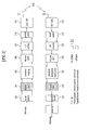
- FIG. 1 shows a network architecture of the E-UMTS.
- the E-UMTS is an evolved form of a WCDMA UMTS, and the standardization thereof is ongoing in the 3GPP.
- the E-UMTS is also called a Long Term Evolution (LTE) system.
- LTE Long Term Evolution
- the E-UMTS may include a User Equipment (UE), a base station (hereinafter, referred to as an "eNode B” or “eNB"), and an Access Gateway (AG) positioned at the end of the network (Universal Terrestrial Radio Access Network: E-UTRAN) and connected to an external network.
- UE User Equipment
- eNode B base station
- AG Access Gateway
- the eNode B may simultaneously transmit multiple data streams, for broadcast services, multicast services and/or unicast services.
- One or more cells may exist in one eNode B.
- a plurality of eNode Bs may be connected by an interface for transmitting the user traffic or control traffic.
- a Core Network (CN) may include the AG and a network node for the user registration of the UE.
- the AG manages the mobility of the UE in the unit of Tracking Areas (TAs).
- the TA is composed of a plurality of cells.
- the UE informs the AG that the TA of the UE is changed.
- LTE-Advanced LTE-Advanced
- the LTE-A requires spatial multiplexing using the MIMO in uplink transmission.
- the LTE-A requires spatial multiplexing up to a maximum of four layers in uplink transmission.
- the LTE-A requires transmission of a maximum of two transmission blocks via one subframe per component carrier in the case of multiplexing by a single user in uplink transmission.
- component carrier refers to a basic frequency block used in carrier aggregation.
- carrier aggregation refers to technology for logically combining a plurality of frequency blocks and supporting a wideband.
- the LTE-A uses the frequency aggregation technology for wideband.
- An object of the present invention devised to solve the problem lies in a method and apparatus for performing uplink transmission via multiple antennas in a radio communication system.
- Another object of the present invention devised to solve the problem lies in a signaling method and apparatus associated with uplink transmission using multiple antennas.
- a further object of the present invention devised to solve the problem lies in a method and apparatus for determining a multi-antenna transmission mode when performing uplink transmission.
- the objects of the present invention can be achieved by providing a method for transmitting a signal from a User Equipment (UE) in a radio communication system, the method including receiving configuration information for multi-antenna transmission from a base station, configuring a multi-antenna transmission mode according to the configuration information, and transmitting an uplink channel having a plurality of symbols (for example, OFDMA or SC-FDMA symbols) to the base station through multiple antennas.
- UE User Equipment
- the objects of the present invention can be achieved by providing a user equipment including multiple antennas, a radio frequency module configured to receive configuration information for multi-antenna transmission from a base station and to transmit an uplink channel having a plurality of symbols (for example, OFDMA or SC-FDMA symbols) to the base station through the multiple antennas according to a set multi-antenna transmission mode, and a processor configured to set the multi-antenna transmission mode according to the configuration information.
- a user equipment including multiple antennas, a radio frequency module configured to receive configuration information for multi-antenna transmission from a base station and to transmit an uplink channel having a plurality of symbols (for example, OFDMA or SC-FDMA symbols) to the base station through the multiple antennas according to a set multi-antenna transmission mode, and a processor configured to set the multi-antenna transmission mode according to the configuration information.
- a radio frequency module configured to receive configuration information for multi-antenna transmission from a base station and to transmit an uplink
- the configuration information may be 1-bit information indicating whether or not a Multiple Input Multiple Output (MIMO) transmission scheme is used.
- MIMO Multiple Input Multiple Output
- the configuration information may indicate the total number of antennas that require channel estimation.
- the configuration information may include uplink scheduling information.
- the uplink channel may be transmitted using an Orthogonal Space Resource Transmission (OSRT) scheme.
- OSRT Orthogonal Space Resource Transmission
- the objects of the present invention can be achieved by providing a method for transmitting a signal from a User Equipment (UE) in a radio communication system, the method including checking one or more resources associated with an uplink channel having a plurality of symbols (for example, OFDMA or SC-FDMA symbols), configuring a multi-antenna transmission mode based on the one or more resources, and transmitting the uplink channel to the base station through multiple antennas.
- UE User Equipment
- the objects of the present invention can be achieved by providing a user equipment including multiple antennas, a radio frequency module configured to transmit an uplink channel having a plurality of symbols (for example, OFDMA or SC-FDMA symbols) to a base station through the multiple antennas according to a set multi-antenna transmission mode, and a processor configured to check one or more resources associated with the uplink channel and to set the multi-antenna transmission mode based on the one or more resources.
- a radio frequency module configured to transmit an uplink channel having a plurality of symbols (for example, OFDMA or SC-FDMA symbols) to a base station through the multiple antennas according to a set multi-antenna transmission mode
- a processor configured to check one or more resources associated with the uplink channel and to set the multi-antenna transmission mode based on the one or more resources.
- the uplink channel may be a Physical Uplink Control CHannel (PUCCH).
- the uplink channel may be a Physical Uplink Shared CHannel (PUSCH) and the one or more resources may be associated with a reference signal.
- PUCCH Physical Uplink Control CHannel
- PUSCH Physical Uplink Shared CHannel
- the one or more resources may include Cyclic Shift (CS), Orthogonal Covering (OC) or a Resource Block (RB), or an arbitrary combination of the CS, OC, and RB.
- CS Cyclic Shift
- OC Orthogonal Covering
- RB Resource Block
- the multi-antenna transmission mode may be determined based on the total number of the one or more resources.
- the multi-antenna transmission mode may be determined based on the number of resources that have a predetermined relationship from among the one or more resources.
- the one or more resources may be indicated using a plurality of fields and the multi-antenna transmission mode may be determined based on whether or not the fields are identical to each other.
- the one or more resources may be indicated for each antenna and the multi-antenna transmission mode may be determined based on whether or not the resources are identical to each other.
- FIG. 1 is a view showing a network architecture of an E-UMTS
- FIG. 2 is a block diagram of a transmitter and a receiver for OFDMA and SC-FDMA;
- FIG. 3 is a view showing the architecture of an uplink transmitter defined in an LTE system
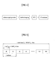
- FIG. 4 is a block diagram illustrating a method for generating a Reference Signal (RS) in an SC-FDMA transmitter
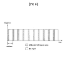
- FIG. 5 is a view showing the architecture of a radio frame
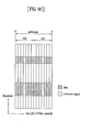
- FIG. 6 is a view showing the architecture of a downlink physical channel
- FIG. 7 is a view showing a resource grid of a slot
- FIGs. 8A and 8B are views showing examples of localized SC-FDMA resource mapping
- FIGs. 9A and 9B are views showing examples of clustered SC-FDMA resource mapping
- FIG. 10 illustrates a structure of an uplink subframe
- FIG. 11 illustrates a PUCCH structure
- FIG. 12 illustrates ACK/NACK channelization for a PUCCH format 1a/1b
- FIG. 13 illustrates ACK/NACK and CQI channelization in a hybrid structure
- FIG. 14 illustrates an exemplary configuration of a radio communication system that uses multiple antennas
- FIG. 15 illustrates an exemplary SC-FDMA transmitter that supports multiple antennas
- FIG. 16 illustrates a Sequence Time Block Coding (STBC) scheme
- FIG. 17 illustrates Cyclic Delay Diversity (CDD).
- FIG. 18 illustrates an Orthogonal Space Resource Transmission (OSRT) scheme
- FIGs. 19 to 24 illustrate procedures for performing uplink transmission through multiple antennas according to an embodiment of the present invention.
- FIG. 25 is a block diagram of a transmitter/receiver according to an embodiment of the present invention.
- An Orthogonal Frequency Division Multiplexing Access (OFDMA) scheme uses an OFDM scheme.
- the OFDM scheme divides a data stream with a high transfer rate into a plurality of data streams with low transfer rate and simultaneously transmits the plurality of data streams using a plurality of orthogonal subcarriers.
- the OFDMA scheme provides some of available subcarriers to users so as to realize multiplexing access.
- the OFDMA scheme has preferable characteristics such as high spectrum efficiency and robustness to multi-path influences.
- the OFDMA scheme has a disadvantage such as high Peak-to-Average Power Ratio (PAPR).
- PAPR Peak-to-Average Power Ratio
- the PAPR As the number of subcarriers via which one user transmits a signal is increased, the PAPR is increased.
- the PAPR converges into about 8 dB at a 95% confidence level.
- a high PAPR is not preferable and may deteriorate system performance.
- peak power may be operated in a nonlinear region or may be clipped to a predetermined value, in a power amplification process. Accordingly, high peak power may cause signal quality deterioration and signal distortion and thereby may have an influence on channel estimation and data detection.
- the SC-FDMA scheme is technology suggested for reducing a high PAPR observed in the OFDMA scheme.
- the SC-FDMA scheme is different from the OFDMA scheme in that data is spread in a frequency domain via Discrete Fourier Transform (DFT) precoding prior to an Inverse Fast Fourier Transform (IFFT) process. If the SC-FDMA scheme is used, the PAPR of a transmitted signal can be further decreased, compared with the case of using the OFDMA scheme.
- the SC-FDMA scheme is also called a DFT-Spread-OFDMA (DFT-s-OFDMA) scheme.
- FIG. 2 is a block diagram of a transmitter and a receiver for OFDMA and SC-FDMA.
- the transmitter may be a portion of a User Equipment (UE) and the receiver may be a portion of a base station (eNode B).
- the transmitter may be a portion of an eNode B and the receiver may be a portion of a UE.
- an OFDMA transmitter includes a serial-to-parallel converter 202, a subcarrier mapping module 206, an M-point IDFT module 208, a Cyclic Prefix (CP) adding module 210, a parallel-to-serial converter 212, and a Radio Frequency (RF)/Digital-to-Analog Converter (DAC) module 214.
- CP Cyclic Prefix
- RF Radio Frequency
- DAC Digital-to-Analog Converter
- a signal processing procedure of the OFDMA transmitter is as follows. First, a bit stream is modulated to a data symbol sequence.
- the bit stream may be obtained by performing various signal processes such as channel encoding, interleaving and scrambling with respect to a data block received from a Medium Access Control (MAC) layer.
- the bit stream may be called a codeword and is equivalent to a data block received from the MAC layer.
- the data block received from the MAC layer is also called a transmission block.
- the modulation scheme may include, but not limited to, Binary Phase Shift Keying (BPSK), Quadrature Phase Shift Keying (QPSK) and n-Quadrature Amplitude Modulation (QAM).
- BPSK Binary Phase Shift Keying
- QPSK Quadrature Phase Shift Keying
- QAM n-Quadrature Amplitude Modulation
- the serial data symbol sequence is serial-to-parallel converted N data symbols by N data symbols (202).
- N data symbols are mapped to allocated N subcarriers out of a total of M subcarriers, and residual M-N subcarriers are padded with 0 (206).
- the data symbols mapped in the frequency domain are converted into a time-domain sequence by M-point IDFT processing (208).
- M-point IDFT processing 208
- CP is added to the time-domain sequence so as to generate OFDMA symbols (210).
- the generated OFDMA symbols are parallel-to-serial converted (212).
- An OFDMA receiver includes an RF/Analog-to-Digital Converter (ADC) module 216, a serial-to-parallel converter 218, a CP removal module 220, an M-point DFT module 224, a subcarrier demapping/equalization module 226, a parallel-to-serial converter 228 and a detection module 230.
- ADC RF/Analog-to-Digital Converter
- serial-to-parallel converter 218 includes RF/Analog-to-Digital Converter (ADC) module 216, a serial-to-parallel converter 218, a CP removal module 220, an M-point DFT module 224, a subcarrier demapping/equalization module 226, a parallel-to-serial converter 228 and a detection module 230.
- the signal processing procedure of the OFDMA receiver is configured inversely to the OFDM transmitter.
- the SC-FDMA transmitter further includes the N-point DFT module 204 in the previous stage of the subcarrier mapping module 206, compared with an OFDMA transmitter.
- the SC-FDMA transmitter spreads plural pieces of data in the frequency domain by the DFT prior to the IDFT processing, thereby further reducing the PAPR of the transmitted signal, compared with the OFDMA scheme.
- the SC-FDMA receiver further includes the N-Point IDFT module 228 in the next stage of the subcarrier demapping module 226, compared with the OFDMA receiver.
- the signal processing procedure of the SC-FDMA receiver is configured inversely to the SC-FDMA transmitter.
- the modules shown in FIG. 2 are only illustrative and the transmitter and/or the receiver may further include a necessary module, some of the modules or functions may be omitted or divided into different modules, or two or more modules may be combined into one module.
- FIG. 3 is a view showing the architecture of an uplink transmitter defined in an LTE system.
- the LTE system uses the SC-FDMA in uplink transmission and uses the OFDMA scheme in downlink transmission.
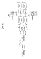
- the SC-FDMA transmitter includes a scrambling module 302, a modulation mapper 304, a transform precoder 306, a resource element mapper 308 and an SC-FDMA signal generation module 310.
- the signal processing procedure is as follows.
- the scrambling module 302 may scramble a bit stream using a specific scrambling code/sequence of a UE.
- the modulation mapper 304 modulates the scrambled signal into complex symbols using a scheme such as a BPSK, QPSK or 16QAM scheme according to the type of the signal and/or the channel state. Thereafter, the modulated complex symbols are processed by the transform precoder 306 and are then input to the resource element mapper 308.
- the resource element mapper 308 maps the complex symbols to scheduled subcarriers. Thereafter, the signals mapped to the subcarriers may be transmitted in uplink via the SC-FDMA signal generation module 310.
- the transform precoder 306 corresponds to the N-point DFT module 204 of FIG. 2 .
- the resource element mapper 308 corresponds to the subcarrier mapping module 206 of FIG. 2 .
- the SC-FDMA signal generation module 310 corresponds to the M-point IDFT module 206, the CP adding module 210 and the parallel-to-serial converter 212 of FIG. 2 .
- the modules shown in FIG. 3 are only illustrative and the SC-FDMA transmitter may further include a necessary module, some of the modules or functions may be omitted or divided into different modules, or two or more modules may be combined into one module.
- the data symbol sequence input to the transform precoder 306 may be complex symbols represented by d(0), ..., and d(M symb -1).
- the transform precoder 306 simultaneously processes N data symbols and divides the data symbol sequence into M symb /N sets. The sets finally configure SC-FDMA symbols.
- N denotes the number of scheduled subcarriers.
- the data symbols input to the transform precoder 306 may be processed by the following Expression.
- the process of Expression 1 corresponds to a DFT process, and frequency-domain sequences represented by D(0), ..., D(M symb -1) are generated by the transform precoder 306.
- the respective values of the frequency-domain sequences determine the sizes and the phases of the mapped subcarriers.
- FIG. 4 is a block diagram illustrating a method for generating a Reference Signal (RS) in an SC-FDMA transmitter.
- RS Reference Signal
- the RS is immediately generated in the frequency domain. That is, the RS does not pass through a DFT precoder.
- the RS is generated using an orthogonal sequence, a quasi-orthogonal sequence, or a sequence having good correlation characteristics.
- the RS may include a computer-generated sequence, a Zadoff-Chu (ZC) sequence, a Constant Amplitude Zero Autocorrelation Waveform (CAZAC) sequence, a Pseudo-random Noise (PN) sequence, or the like.
- ZC Zadoff-Chu
- CAZAC Constant Amplitude Zero Autocorrelation Waveform
- PN Pseudo-random Noise
- the RS is mapped to a plurality of subcarriers in the frequency domain.
- the RS may be continuously or discontinuously mapped to the frequency domain.
- the RS mapped to the frequency domain is transformed into a time-domain signal through an IFFT.
- the time-domain signal is transmitted to a receiving end
- FIG. 5 is a view showing the architecture of a radio frame.
- the radio frame has a length of 10 ms and includes 10 subframes.
- Each of the subframes has a length of 1 ms and includes two slots.
- Each of the slots has a length of 0.5 ms.
- Each slot includes a plurality of transmission symbols in a time domain, and includes a plurality of resource blocks (RBs) in a frequency domain.
- a Transmission Time Interval (TTI) which is a unit time for transmission of data may be determined in units of one or more subframes.
- the structure of the radio frame is only exemplary and the number of subframes, the number of slots, and the number of transmission symbols may be variously changed.
- FIG. 6 is a view showing the architecture of a downlink physical channel.
- each subframe includes a control region for transmitting scheduling information and other control information and a data region for transmitting downlink data.
- the control region starts from a first OFDMA symbol of the subframe and includes one or more OFDMA symbols.
- the size of the control region may be independently set with respect to each subframe.
- Various control channels including a Physical Downlink Control Channel (PDCCH) are mapped to the control region.
- the PDCCH is a physical downlink control channel, which is allocated to first n OFDM symbols of the subframe.
- the PDCCH includes one or more Control Channel Elements (CCEs).
- Each CCE includes 9 adjacent Resource Element Groups (REGs).
- Each REG includes four adjacent Resource Elements (REs) excluding a reference signal.
- the PDCCH informs each UE of information associated with resource allocation of a Paging Channel (PCH) and a Downlink-Shared Channel (DL-SCH), uplink scheduling grant, Hybrid Automatic Repeat Request (HARQ) information, or the like.
- the information transmitted via the PDCCH is collectively referred to as Downlink Control Information (DCI).
- DCI Downlink Control Information
- the PDCCH has various formats according to transmission information.
- the PDCCH format is also called a DCI format. For example, a DCI format 0 associated with uplink scheduling is shown in Table 1.
- Radio Network Temporary Identifier it is identified to which UE the PDCCH is transmitted. For example, it is assumed that the PDCCH is CRC-masked with an RNTI "A”, and uplink radio resource allocation information (e.g., frequency location) "B” and transmission format information (e.g., transmission block size, modulation scheme, coding information, or the like) "C" are transmitted.
- uplink radio resource allocation information e.g., frequency location
- B uplink radio resource allocation information
- transmission format information e.g., transmission block size, modulation scheme, coding information, or the like
- FIG. 7 is a view showing a resource grid of a slot.
- FIG. 7 is equally applicable to a downlink slot.
- the uplink slot includes a plurality of SC-FDMA symbols in a time domain, and includes a plurality of RBs in a frequency domain.
- the uplink slot includes 7 SC-FDMA symbols and the RB includes 12 subcarriers, the present invention is not limited thereto.
- the number of SC-FDMA symbols included in the uplink slot may be modified according to the length of a cyclic prefix. Elements on the resource grid are called resource elements.
- One RB includes 12x7 resource elements.
- the number N UL RB of RBs included in the uplink slot depends on an uplink transmission bandwidth set in a cell.
- SC-FDMA may be subdivided according to a method for mapping frequency-domain sequences generated by DFT precoding to subcarriers. For convenience, localized SC-FDMA and clustered SC-FDMA will be described.
- FIGs. 8A and 8B are views showing examples of localized SC-FDMA resource mapping.
- N u data symbols are input to an N u -DFT module.
- N u denotes the number of subcarriers scheduled at a given time point.
- the N u -DFT module generates frequency-domain sequences with a length of N u , which are spread in the frequency domain, from the N u data symbols.
- the frequency-domain sequences output from the N u -DFT module are continuously allocated to N u subcarriers within a system band (including N c subcarriers). Thereafter, a localized SC-FDMA symbol is generated through an N c -point IFFT module.
- each slot may include 7 SC-FDMA symbols and data that has been subjected to DFT precoding may be mapped to a plurality of consecutive subcarriers.
- a resource is generated in the frequency domain and is mapped to a 4th SC-FDMA symbol of each slot.
- each slot may include 6 SC-FDMA symbols and a reference signal may be mapped to a 3rd SC-FDMA symbol of each slot. Since the localized SC-FDMA symbol has a single carrier characteristic on a time axis, a PAPR is smaller than that of an OFDMA symbol.
- the localized SC-FDMA scheme can perform frequency selective scheduling, it reduces scheduling flexibility. For example, a transmitter and a receiver cannot simultaneously transmit data through a plurality of separated frequency regions having good radio channel response characteristics.
- FIGs. 9A and 9B are views showing examples of clustered SC-FDMA resource mapping.
- the N u -DFT module generates frequency-domain sequences with a length of N u , which are spread in the frequency domain, from the N u data symbols.
- the frequency-domain sequences output from the N u -DFT module are discontinuously mapped to one or more clusters set within a system band (N c subcarriers) by a subcarrier mapping process.
- the cluster indicates a frequency band to which the localized SC-FDMA scheme is applied and includes one or more continuous subcarriers.
- the data symbols are discontinuously mapped to a plurality of clusters in a frequency domain, and are continuously mapped to one or more subcarriers within each of the clusters.
- clustered SC-FDMA symbols may be generated by an N c -point IFFT module.
- the SC-FDMA scheme may be separately performed for each sub-band.
- each sub-band may be a component carrier used for a carrier aggregation.
- Each sub-band may be adjacent to each other or may be separated from each other in the frequency domain.
- the system band includes three sub-bands.
- the size of each sub-band may be equal or unequal.
- the SC-FDMA scheme is applied to each sub-band in the same manner as described above with reference to FIG. 9A .
- IFFT may be performed for the entire system band or may be performed on a sub-band basis as shown.
- Each SC-FDMA symbol generated through IFFT may be transmitted using a single central carrier or may be transmitted in units of subbands using different central carriers as shown.
- each slot may include 7 SC-FDMA symbols and data that has been subjected to DFT precoding may be mapped to one or more clusters.
- a reference signal may be generated in the frequency domain and may then be mapped to a 4th SC-FDMA symbol of each slot.
- the example of FIG. 9C shows the case where the number of clusters is 2.
- the sizes of the clusters e.g., the number of subcarriers
- each slot may include 6 SC-FDMA symbols and a reference signal may be mapped to a 3rd SC-FDMA symbol of each slot.
- FIG. 10 illustrates an uplink subframe structure.
- an uplink subframe may be divided into a region to which a Physical Uplink Control CHannel (PUCCH) carrying control information is allocated and a region to which a Physical Uplink Shared CHannel (PUSCH) carrying user data is allocated.
- the center part of the subframe is allocated to the PUSCH, and both-side parts of the data region are allocated to the PUCCH in the frequency domain.
- Control information transmitted over the PUCCH includes an Acknowledgement/Negative-Acknowledgement (ACK/NACK) used in a Hybrid Automatic Repeat Request (HARQ), a Channel Quality Indictor (CQI) indicating a downlink channel state, a Rank Indicator (RI) for MIMO, a scheduling request (SR) which is as a UL resource allocation request, etc.
- ACK/NACK Acknowledgement/Negative-Acknowledgement
- HARQ Hybrid Automatic Repeat Request
- CQI Channel Quality Indictor
- RI Rank Indicator
- SR scheduling request
- a PUCCH for one UE uses one resource block (RB) that occupies a different frequency in each slot of the subframe. That is, two RBs allocated to a PUCCH are frequency-hopped at a slot boundary.
- the PUCCH may support multiple formats. That is, uplink control information having a different number of bits per subframe depending on a used modulation scheme may be transmitted within a PUCCH.
- 1-bit control information may be transmitted within a PUCCH when a Binary Phase Shift Keying (BPSK) is used and 2-bit control information may be transmitted within a PUCCH when a Quadrature Phase Shift Keying (QPSK) is used.
- BPSK Binary Phase Shift Keying
- QPSK Quadrature Phase Shift Keying
- Table 2 illustrates a PUCCH format in an LTE system.
- Table 3 illustrates the number of reference signals for demodulation per slot according to the PUCCH format.
- FIG. 11A illustrates a PUCCH 1a/1b structure. An ACK/NACK signal is transmitted in this structure.
- each slot includes 7 SC-FDMA symbols.
- a reference signal is carried within 3 consecutive SC-FDMA symbols and an ACK/NACK signal is carried within 4 remaining SC-FDMA symbols.
- each slot includes 6 SC-FDMA symbols and a reference signal is carried within the 3rd and 4th SC-FDMA symbols.
- Resources for ACK/NACK signals are identified using different Walsh/DFT orthogonal codes (time spreads) and different Cyclic Shifts (CSs) of a Computer Generated Constant Amplitude Zero Auto Correlation (CG-CAZAC). After IFFT, the signal is multiplied by w0, w1, w2, and w3.
- Resource blocks for the ACK/NACK signal are allocated so as to be orthogonal to each other in the frequency domain. Assuming that the number of available cyclic shifts is 6 and the number of available Walsh/DFT codes is 3, 18 UEs may be multiplexed within one Resource Block (RB).
- RB Resource Block
- FIG. 11B illustrates a PUCCH 1a/1b structure. A CQI signal is transmitted in this structure.
- each slot includes 7 SC-FDMA symbols and a reference signal is carried within 2nd and 6sh SC-FDMA symbols.
- a CQI signal is carried within the remaining SC-FDMA symbols.
- each slot includes 6 SC-FDMA symbols and a reference signal is carried within the 4th SC-FDMA symbol.
- the CQI is modulated and carried over the entire SC-FDMA symbol and each SC-FDMA symbol is configured as one sequence. That is, the UE modulates and transmits a CQI in each sequence.
- the CQI is modulated in a QPSK scheme and a subframe may carry a CQI value of up to 20 bits.
- a reference signal may be UE-multiplexed in a Code Division Multiplexing (CDM) manner through cyclic shift. For example, when the number of available cyclic shifts is 12, 12 UEs may be multiplexed in the same RB and, when the number of available cyclic shifts is 6, 6 UEs may be multiplexed in the same RB.
- CDM Code Division Multiplexing
- the PUCCH resources include frequency resource blocks, orthogonal codes, and cyclic shifts of sequences.
- Expression 2 represents a basic CG-CAZAC sequence of length 12.
- u and ⁇ (n) are the same as defined in Table 5 and n is an integer in a range of 0 to 11.
- Tables 5 and 6 illustrate orthogonal sequences of lengths 4 and 3 used in each PUCCH.
- Table 7 illustrates an orthogonal sequence used in a reference signal.
- Expression 3 represents a Physical Resource Block (PRB) used for PUCCH transmission in slot n s .
- PRB Physical Resource Block
- m is determined according to a PUCCH format. Specifically, "m" which is determined according to PUCCH formats 1/1a/1b and 2/2a/2b as represented in Expressions 4 and 5.
- FIG. 12 illustrates ACK/NACK channelization for a PUCCH format 1a/1b. This example is similarly applied to the PUCCH format 2/2a/2b.
- ACK/NACK channelization is determined based on a combination of orthogonal covering (OC) and a cyclic shift (CS) of a CG-CAZAC sequence.
- ACK/NACK channels are combined so as to be as far away from each other as possible in CS and OC resources.
- a CS difference ( ⁇ PUCCH shift ) between adjacent ACK/NACK channels is determined for each cell and has a value of 1, 2, or 3. In this embodiment, it is assumed that the CS difference ( ⁇ PUCCH shift ) is 2. In this case, ACK/NACK channelization is performed using OC resources after it is performed using CS resources.
- ACK/NACK resources are represented in the form of (CS, OC)
- the resources for ACK/NACK channels are given as (1,0), (3,0), (5,0), (9,0), (11,0), (2,1), (4,1), (6,1), ..., (7, 2), (9, 2), (11, 2).
- ACK/NACK resources i.e., CS, Walsh/DFT code, and frequency RB resources
- CS Walsh/DFT code, and frequency RB resources
- FIG. 13 illustrates ACK/NACK and CQI channelization in a hybrid structure.
- resources for ACK/NACK and CQI are identified by CSs.
- CSs of 0 to 3 may be used for ACK/NACK channelization and CSs of 5 to 10 may be used for CQI channelization.
- CSs of 4 and 11 may be used as guard CSs for avoiding interference between channels.
- CSs may be hopped on a symbol basis to randomize interference between cells.
- CS/OC may be remapped on a slot basis.
- resources of PUCCH format 1/1a/1b are configured as combinations of a Cyclic Shift (CS), orthogonal covering (OC), and a Resource Block (RB).
- CS Cyclic Shift
- OC orthogonal covering
- RB Resource Block
- PUCCH format 2/2a/2b resources are configured as combinations of a Cyclic Shift (CS) and a Resource Block (RB).
- CS Cyclic Shift
- RB Resource Block
- a reference signal used for a PUSCH.
- a reference signal is configured as a CG-CAZAC or CAZAC sequence.
- Expression 6 represents a reference signal for a PUSCH.
- n is an integer in a range from 0 to M Rs SC -1
- M RS SC denotes the number of scheduled subcarriers.
- u denotes a group index which is an integer in a range of 1 to 29.
- v denotes a basic sequence number belonging to each group. Each group includes one basic sequence for resources of 5 or less RBs and two basic sequences for resources of 6 or more RBs.
- ⁇ denotes a Cyclic Shift (CS) value and is defined as 2 ⁇ n cs /12.
- n CS is expressed as Expression 7.
- n cs n DMRS 1 + n DMRS 2 + n PRS n s ⁇ mod 12
- n (1) DMRS denotes a broadcast value and n (2) DMRS is indicated by scheduling as illustrated in Table 9.
- n PRS (n S ) denotes a cell-specific CS value and varies depending on the slot number (n S ).
- n PRS (n S ) may be expressed as Expression 8.
- c(i) is a cell-specific Pseudo-random Noise (PN) sequence.
- the PN sequence generator is initialized as a value as expressed in Expression 9.
- Physical mapping of a reference signal for a PUSCH is performed in the following manner.
- a sequence r PUSCH ( ⁇ ) is multiplied by an amplitude scaling factor ⁇ PUSCH and is mapped to a physical RB used for corresponding PUSCH transmission, starting from r PUSCH (0).
- FIG. 14 illustrates an exemplary configuration of a radio communication system using multiple antennas.
- MIMO technology refers to technology for performing communication using multiple transmission antennas and/or multiple reception antennas.
- the MIMO technology includes a transmit diversity (TxD) scheme for increasing transmission reliability using symbols passing through various channel paths and a spatial multiplexing (SM) scheme for simultaneously transmitting a plurality of data symbols using a plurality of transmission antennas so as to improve transfer rate.
- TxD transmit diversity
- SM spatial multiplexing
- the transmit diversity scheme includes a space-time block coding (STBC) scheme and a space-time trellis coding scheme simultaneously using a diversity gain and a coding gain.
- STBC space-time block coding
- the space-time trellis coding scheme is excellent in terms of bit error rate improvement performance and degree of freedom in code generation, but the space-time block coded scheme is simple in terms of computational complexity.
- the transmit diversity gain is an amount corresponding to the product of the number of transmission antennas and the number of reception antennas.
- the transmit diversity scheme includes a Cyclic Delay Diversity (CDD), Precoding Vector Switching (PVS), Time Switched Transmit Diversity (TSTD), Single Carrier-Space Frequency Block Coding (SC-SFBC), STBC-II, Frequency Shift Time Diversity (FSTD), and the like.
- CDD Cyclic Delay Diversity
- PVS Precoding Vector Switching
- TSTD Time Switched Transmit Diversity
- SC-SFBC Single Carrier-Space Frequency Block Coding
- STBC-II Frequency Shift Time Diversity
- the receiver detects a signal after eliminating the interference using a proper signal processing scheme.
- the interference eliminating scheme include a Maximum Likelihood (ML) scheme, a Zero Forcing (ZF) scheme, a Minimum Mean Square Error (MMSE) scheme, a Diagonal Bell laboratories Layered Space-Time (D-BLAST) scheme, a Vertical Bell laboratories Layered Space-Time (V-BLAST) scheme, and the like.
- ML Maximum Likelihood
- ZF Zero Forcing
- MMSE Minimum Mean Square Error
- D-BLAST Diagonal Bell laboratories Layered Space-Time
- V-BLAST Vertical Bell laboratories Layered Space-Time
- Singular Value Decomposition Singular Value Decomposition
- a hybrid of the transmit diversity scheme and the spatial multiplexing scheme may be used. If only the spatial diversity gain is obtained, a performance improvement gain according to the increase in diversity order is gradually saturated and, if only a spatial multiplexing gain is obtained, transmission reliability is reduced in a radio channel.
- Such a hybrid scheme includes a Double-Space Time Transmit Diversity (D-STTD) scheme, a Space Time Bit-Interleaved Coded modulation (STBICM) scheme, and the like.
- Equation 6 represents signals x 1 , x 2 , ..., x N T that are transmitted through transmit antennas.
- w ij denotes a weight applied between an ith transmit antenna and ⁇ denotes a power-adjusted information vector S.
- W denotes a weight or precoding matrix. W is appropriately distributed to each antenna according to a channel state.
- the spatial multiplexing scheme since different signals are transmitted in a state of being multiplexed, all the elements of the information vector S have different values.
- the transmit diversity scheme since the same signal is transmitted via several channel paths, all the elements of the information vector S have the same value.
- a method for mixing the spatial multiplexing scheme and the transmit diversity scheme may be considered. For example, the same signal may be transmitted via three transmission antennas and different signals may be respectively transmitted via the residual transmission antennas.
- Equation 7 represents signals y 1 , y 2 , ..., y N R that are transmitted through receive antennas when NR transmit antennas are present.
- H denotes a channel matrix
- h ij denotes a channel from a transmit antenna j to a receive antenna i.
- the rank of the matrix is defined by a minimum number of the number of independent rows or columns. Accordingly, the rank rank ( H ) of the channel matrix H is restricted as follows.
- the rank may be defined by the number of Eigen values excluding 0, when the matrix is subjected Eigen value decomposition. Similarly, the rank may be defined by the number of singular values excluding 0, when singular value decomposition is performed. Accordingly, the physical meaning of the rank in the channel matrix is a maximum value of pieces of different information, which can be transmitted via a given channel.
- a transmitter and a receiver may share a codebook for applying the MIMO technology.
- the codebook is a predefined set of precoding matrices or vectors.
- the precoding matrix has a size of N T ⁇ N L .
- N T denotes the number of (physical or logical) antennas used for signal transmission
- N L denotes the number of layers. That is, the layers correspond to the (physical or logical) antennas and a relationship between the layers and the antennas may be determined by the precoding matrix.
- the number of layers may be determined according to the rank of the channel matrix.
- the precoding matrix may be configured in a nested format. Meanwhile, if two antenna ports are used in LTE, the codebook is defined as shown in Table 9. If four antenna ports are used, the codebook may refer to 3GPP TS36.211.
- FIG. 15 is a view showing an example of an SC-FDMA transmitter for supporting multiple antennas.
- scrambling module 1510#1 to 1510#N CW may scramble N CW codewords (CW) using specific scrambling codes/sequences of a UE.
- the N CW scrambled signals are input to modulation mappers 1520#1 to 1520#N CW so as to be modulated to complex symbols by a BPSK, QPSK or 16QAM scheme according to the kinds of the transmitted signals and/or the channel states. Thereafter, the N CW modulated complex symbols are mapped to N L layers by a layer mapper 1530.
- the layers are DFTed by respective transformer precoders 1540#1 to 1540#N T .
- a precoder 1545 maps the N L DFTed layers to N T streams corresponding to the antenna ports using precoding vectors/matrices. That is, a relationship between the layers and the antennas may be determined by the precoding vectors/matrices.
- Resource element mappers 1550#1 to 1550#N T map the N T streams to subcarriers.
- SC-FDMA signal generators 1560#1 to 1560#N T convert the signals mapped to the subcarriers into transmission symbols in the time domain and then transfer the symbols to the antenna ports.
- the antenna ports are mapped to the physical antennas through antenna virtualization.
- the layers mapper 1530 and the precoder 1545 are illustrated as separate modules in this embodiment, the functions of the layer mapper 1530 and the precoder 1545 may be integrated as a single module.
- the functions of the layer mapper 1530 may be incorporated into the precoder 1545 and the functions of the precoder 1545 may be incorporated into the layer mapper 1530.
- the precoder 1545 is illustrated as being located in the transform precoders 1540#1 to 1540#N T in this embodiment, the precoder 1545 may also be located before the transform precoders 1540#1 to 1540#N T or after an IFFT module (not shown).
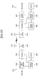
- FIG. 16 illustrates a Sequence Time Block Coding (STBC) scheme.
- STBC is a scheme which performs frequency-time block coding to acquire transmit diversity gain while satisfying single carrier characteristics so as to lower Cubic Metric (CM) characteristics.
- CM Cubic Metric
- a QAM symbol of length 2M is generated from information bits through QAM symbol modulation.
- Length M-point DFT coding is performed on the QAM symbol of length 2M to perform STBC mapping.
- Antenna #0, OFDM symbol #0 Symbols of indices 0 to M-1 are mapped after being DFTed.
- Antenna #1, OFDM symbol #0 > Symbols of indices M to 2M-1 are mapped after being DFTed.
- Antenna #0, OFDM symbol #1 Symbols of indices M to 2M-1 are DFTed and multiplied by "-1" and are then mapped after complex conjugation is performed (or the DFTed value used when the antenna #1, OFDM symbol #0 mapping is performed is multiplied by "-1" and then complex conjugation is performed).
- Antenna #1, OFDM symbol #1 Symbols of indices 0 to M-1 are DFTed and multiplied by "-1" and are then mapped after complex conjugation is performed (or the DFTed value used for when the antenna #0, OFDM symbol #0 mapping is performed is multiplied by "-1" and then complex conjugation is performed).
- the STBC scheme When the STBC scheme is applied to a PUCCH format 2/2a/2b, the STBC scheme may be applied to modulation symbols before or after being spread using orthogonal resources.
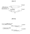
- FIG. 17 illustrates Cyclic Delay Diversity (CDD).
- the same signal is transmitted through multi-antenna transmission and a different cyclic shift (or linear delay) is applied to a signal corresponding to an OFDM symbol unit or a specific period unit for each antenna to acquire diversity gain.
- a symbol transmitted through antenna #1 is cyclically shifted by ⁇ .
- FIG. 18 illustrates an Orthogonal Space Resource Transmission (OSRT) scheme.
- the OSRT scheme is also referred to as an Orthogonal Resource Transmission (ORT) scheme.
- ORT Orthogonal Resource Transmission
- modulation symbols transmitted through multiple antennas may use different orthogonal resources.
- the orthogonal resources include cyclic shift, orthogonal covering, and frequency resource block. That is, resources (such as cyclic shift, orthogonal covering, and frequency resource block) of modulation symbols transmitted through multiple antennas are set to be orthogonal to each other, thereby guaranteeing orthogonality between UEs while acquiring high diversity gain.
- This embodiment is illustrated with reference to the case where modulation symbols (d_0(n)) are spread using different sequences for multiple antennas.
- the OSRT scheme may be applied to PUCCH transmission.
- the LTE-A system requires that multiple antennas be used in uplink and a variety of MIMO transmission schemes are under consideration in the LTE-A system.
- MIMO transmission scheme for example, TxD scheme and SM scheme.
- TxD scheme for example, TxD scheme and SM scheme.
- a PUCCH in order to use a 2-TxD scheme, two different resources indicated by a combination of a CS, an OC, and a PRB are needed to estimate respective channels of multiple antennas from the viewpoint of reference signal.
- two CSs need to be allocated to estimate respective channels of antennas from the viewpoint of reference signal or two resources (or two resource units) multiplexed in an FDM/TDM manner need to be allocated to perform antenna channel estimation.
- the base station eNode B
- MIMO transmission mode multi-antenna transmission mode
- N-Tx transmission or “N-Tx antenna transmission” refers to transmission that requires channel estimation for each of the N antennas.
- the term “N-Tx transmission” may also be referred to as a transmission mode for N layer transmission.
- N-Tx transmission may also be referred to as a transmission mode for N layer transmission.
- two of the four antennas may use STBC, SFBC, OSRT, and the like and the remaining two antennas may use a virtualization method such as CDD or PVS. That is, although the UE performs transmission using four antennas, it appears to the base station that the UE performs transmission using two antennas.
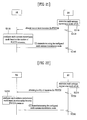
- FIG. 19 illustrates a procedure in which uplink transmission is performed through multiple antennas according to an embodiment of the present invention.
- the base station determines a multi-antenna transmission mode, of the UE (for example, transmit diversity, spatial multiplexing, and the like) (S1910).
- the multi-antenna transmission mode may be determined taking into consideration the channel condition, the number of UEs that are going to perform uplink transmission, and the like.
- the base station signals information regarding the multi-antenna transmission mode to the UE (S1920).
- the information regarding the multi-antenna transmission mode may include information indicating whether or not a MIMO transmission scheme is used, the MIMO transmission scheme, the number of antennas that require channel estimation, and the like.
- the information regarding the multi-antenna transmission mode may include information indicating whether or not transmit diversity (TxD) is used.
- the information regarding the multi-antenna transmission mode may indicate whether or not 1-TxD, 2-TxD, 4-TxD, or the like are used.
- the information regarding the multi-antenna transmission mode may include information indicating whether or not spatial multiplexing (SM) is used.
- the information regarding the multi-antenna transmission mode may include rank information, information regarding the number of layers, and the like.
- the information regarding the multi-antenna transmission mode may be transmitted through one of system information, Radio Resource Control (RRC) signaling, and uplink scheduling information.
- RRC Radio Resource Control
- the information regarding the multi-antenna transmission mode may be transmitted through a newly added field or may be transmitted through a field that is not being used among predefined fields.
- the information regarding the multi-antenna transmission mode may be transmitted in a periodic, aperiodic, persistent, semi-persistent, or event-triggering manner.
- the UE configures its multi-antenna transmission mode as indicated by the base station (S1930). Thereafter, the UE transmits an uplink signal through multiple antennas according to the configured multi-antenna transmission mode (S1940).
- the uplink signal may be transmitted through an uplink channel including a plurality of SC-FDMA symbols. In this case, the uplink channel includes a PUCCH or a PUSCH.
- FIG. 20 illustrates a procedure in which uplink transmission is performed through multiple antennas according to another embodiment of the present invention.
- the base station determines a multi-antenna transmission mode of the UE (for example, transmit diversity, spatial multiplexing, and the like) (S2010).
- the multi-antenna transmission mode may be determined taking into consideration the channel condition, the number of UEs that are going to perform uplink transmission, and the like.
- the base station signals 1-bit information regarding the multi-antenna transmission mode to the UE (S2020).
- the 1-bit information may indicate a non-TxD mode or a TxD mode.
- the 1-bit information may indicate a non-TxD mode when the 1-bit information is set to 0 and indicate a 2-TxD mode when the 1-bit information is set to 1.
- the 1-bit information may also be interpreted reversely.
- the 1-bit information may indicate a non-SM mode or an SM mode.
- the 1-bit information may indicate a mode for transmission of 1 layer when the 1-bit information is set to 0 and indicate a mode for transmission of 2 layers when the 1-bit information is set to 1.
- the 1-bi t information may be transmitted through one of system information, Radio Resource Control (RRC) signaling, and uplink scheduling information.
- RRC Radio Resource Control
- the 1-bit information may be transmitted through a newly added field or may be transmitted through a field that is not being used among predefined fields.
- the 1-bit information may be transmitted in a periodic, aperiodic, persistent, semi-persistent (broadcast channel), or event-triggering (UE-RRC signaling) manner.
- the UE configures its multi-antenna transmission mode as indicated by the base station (S2030). Thereafter, the UE transmits an uplink signal through multiple antennas according to the configured multi-antenna transmission mode (S2040).
- the uplink signal may be transmitted through an uplink channel including a plurality of SC-FDMA symbols.
- the uplink channel includes a PUCCH or a PUSCH.
- FIG. 21 illustrates a procedure in which uplink transmission is performed through multiple antennas according to another embodiment of the present invention.
- the base station determines a multi-antenna transmission mode of the UE (for example, transmit diversity, spatial multiplexing, and the like) (S2110).
- the multi-antenna transmission mode may be determined taking into consideration the channel condition, the number of UEs that are going to perform uplink transmission, and the like.
- the base station allocates one or more PUCCH resources to the UE (S2120).
- the PUCCH resources that can be allocated to the UE may be implicitly derived according to the multi-antenna transmission mode determined in step S2110.
- the PUCCH resources that can be allocated to the UE may be implicitly derived according to the number of antennas determined in step S2110 and a corresponding transmission mode.
- the PUCCH resources may be indicated by (CS, OC, PRB) or (CS, PRB) according to the format. Resources for the reference signal may be indicated by (CS, OC, PRB).
- the maximum number of PUCCH resources may be set to be equal to or less than the number of antennas of the UE. For example, when the number of antennas of the UE is 4, the maximum number of PUCCH resources may be set to 2 or 4.
- the PUCCH resources may be allocated using system information, Radio Resource Control (RRC) signaling, or uplink scheduling information. In this case, the PUCCH resources may be transmitted through a newly added field or may be allocated through a field that is not being used among predefined fields. In addition, the PUCCH resources may be allocated using PDCCH configuration information.
- RRC Radio Resource Control
- resources associated with a PUCCH format 1a/1b for transmitting an ACK/NACK signal may be checked based on information (for example, a last CCE index) regarding CCEs constituting the PDCCH.
- the PUCCH resources may be allocated in a periodic, aperiodic, persistent, semi-persistent, or event-triggering manner.
- the UE configures a multi-antenna transmission mode based on the number of PUCCH resources allocated by the base station (S2130). That is, the number of resources allocated by the base station may be connected to the multi-antenna transmission mode (for example, the number of antennas and a corresponding transmission mode).
- the UE may configure the multi-antenna transmission mode to 1-TxD or its equivalent method such as CDD or PVS.
- the UE may configure the multi-antenna transmission mode to 2-TxD (for example, STBC, SFBC, large delay CDD, OSRT, or the like).
- the base station has allocated four resources (or four resource units)
- the UE may configure the multi-antenna transmission mode to 4-TxD.
- the base station has allocated one resource
- the UE may configure the multi-antenna transmission mode to a transmission mode for one layer transmission.
- the UE may configure the multi-antenna transmission mode to a transmission mode for two layer transmission.
- the UE may configure the multi-antenna transmission mode to a transmission mode for four layer transmission.
- the UE transmits an uplink signal through multiple antennas according to the configured multi-antenna transmission mode (S2140).
- the uplink signal may be transmitted through an uplink channel including a plurality of SC-FDMA symbols.
- the uplink channel includes a PUCCH or a PUSCH.
- FIG. 22 illustrates a procedure in which uplink transmission is performed through multiple antennas according to another embodiment of the present invention.
- the base station determines a multi-antenna transmission mode of the UE (for example, transmit diversity, spatial multiplexing, and the like) (S2210).
- the multi-antenna transmission mode may be determined taking into consideration the channel condition, the number of UEs that are going to perform uplink transmission, and the like.
- the base station allocates a plurality of PUCCH resources to the UE (S2220).
- a relationship between PUCCH resources that can be allocated to the UE may be implicitly derived according to the multi-antenna transmission mode determined in step S2210.
- the PUCCH resources that can be allocated to the UE may be implicitly derived according to the number of antennas determined in step S2210 and a corresponding transmission mode.
- the PUCCH resources may be indicated by (CS, OC, PRB) or (CS, PRB) according to the format.
- Resources for the reference signal may be indicated by (CS, OC, PRB).
- the number of PUCCH resources may be fixed to a specific value equal to or less than the number of antennas of the UE. For example, when the number of antennas of the UE is 4, the number of PUCCH resources may always be fixed to 2 or 4.
- the PUCCH resources may be allocated using system information, Radio Resource Control (RRC) signaling, or uplink scheduling information.
- RRC Radio Resource Control
- the PUCCH resources may be transmitted through a newly added field or may be allocated through a field that is not being used among predefined fields.
- the PUCCH resources may be allocated using PDCCH configuration information. For example, resources associated with a PUCCH format 1a/1b for transmitting an ACK/NACK signal may be checked based on information (for example, last CCE information) regarding CCEs constituing the PDCCH.
- the PUCCH resources may be allocated in a periodic, aperiodic, persistent, semi-persistent, or event-triggering manner.
- the UE configures a multi-antenna transmission mode based on a relationship between PUCCH resources allocated by the base station (S2230). That is, the relationship between resources allocated by the base station may be connected to the multi-antenna transmission mode (for example, the number of antennas and a corresponding transmission mode). For example, the UE may configure a multi-antenna transmission mode based on whether or not the allocated PUCCH resources are identical. In one method, two fields indicating resources to be used for each antenna (or layer 0) may be defined for 2-Tx antenna transmission.
- the UE may perform 2-Tx antenna transmission (for example, STBC, SFBC, large delay CDD, or OSRT) when the two fields have different values and may perform 1-Tx antenna transmission or corresponding transmission when the two fields have the same value.
- 2-Tx antenna transmission for example, STBC, SFBC, large delay CDD, or OSRT
- the base station has allocated nr0 and nr1 to the UE.
- nr0 represents (ncs0, noc0, n_PRB0) for the PUCCH format 1/1a/1b and represents (ncs0, n_PRB0) for the PUCCH format 2/2a/2b.
- ncs represents a cyclic shift value
- noc represents orthogonal covering value
- n_PRB represents a value regarding a physical resource block.
- the order (or sequence) of allocation may correspond to that of a respective antenna (or layer). That is, signaling of (nr0, nr1) may indicate that nr0 has been allocated for antenna 0 (or layer 0) and nr1 has been allocated for antenna 1 (or layer 1).
- the resources and the antennas may have the relationship of (nr0, nr1, nr2, nr3) ⁇ -> (ant0, ant1, ant2, ant3).
- ant may indicate an antenna port (or layer).
- the UE may perform transmission using a Tx transmission method in which multiple antennas can be grouped and assumed as one antenna when the resources allocated for respective antennas (or layers) have the same value and may perform transmission using a predefined multi-antenna transmission mode (for example, transmit diversity, spatial multiplexing, or the like) when the resources allocated for respective antennas (or layers) have different values.
- a predefined multi-antenna transmission mode for example, transmit diversity, spatial multiplexing, or the like
- 4-Tx antenna transmission may be performed when nr0 ⁇ nr1 ⁇ nr2 ⁇ nr3.
- Transmission of ant0 and ant1 may be performed such that it appears that single antenna transmission is performed and transmission of ant2 and ant3 may be performed such that it appears that single antenna transmission is performed, resulting in that it appears from the overall viewpoint that 2-Tx transmission is performed.
- FIG. 23 illustrates a procedure in which uplink transmission is performed through multiple antennas according to another embodiment of the present invention.
- the base station determines a multi-antenna transmission mode of the UE (for example, transmit diversity, spatial multiplexing, and the like) (S2310).
- the multi-antenna transmission mode may be determined taking into consideration the channel condition, the number of UEs that are going to perform uplink transmission, and the like.
- the base station signals the number of Tx antennas that require channel estimation (S2320).
- the number of Tx antennas requiring channel estimation may be implicitly derived according to the multi-antenna transmission mode determined in step S2310.
- the number .of Tx antennas requiring channel estimation may be implicitly derived according to the number of antennas determined in step S2310 and a corresponding transmission mode.
- the number of Tx antennas requiring channel estimation may be allocated using system information, Radio Resource Control (RRC) signaling, or uplink scheduling information.
- RRC Radio Resource Control
- the number of Tx antennas requiring channel estimation may be transmitted through a newly added field or may be allocated through a field that is not being used among predefined fields.
- the number of Tx antennas requiring channel estimation may be allocated in a periodic, aperiodic, persistent, semi-persistent, or event-triggering manner.
- the number of Tx antennas requiring channel estimation may be indicated through the number of CDM/FDM/TDM resources for a reference signal.
- the reference signal resources may be indicated by CS, OC, and PRB or an arbitrary combination thereof.
- the reference signal resources may be indicated using CS.
- the UE may configure the multi-antenna transmission mode according to the number of allocated resources (S2330). That is, the number of resources allocated by the base station may be connected to the multi-antenna transmission mode (for example, the number of antennas and a corresponding transmission mode).
- the UE may configure the multi-antenna transmission mode to a 1-Tx transmission mode when the number of allocated resources is 1, a 2-Tx transmission mode when the number of allocated resources is 2, and a 4-Tx transmission mode when the number of allocated resources is 4. Thereafter, the UE transmits an uplink signal to the base station through multiple antennas using the configured multi-antenna transmission mode (S2340). In this case, the UE transmits a reference signal for a plurality of antennas to the base station using the allocated resources.
- step S2330 only "N" for N-Tx transmission may be signaled as the number of Tx antennas requiring channel estimation.
- the UE configures the multi-antenna transmission mode to N-Tx transmission.
- the UE transmits an uplink signal to the base station through multiple antennas using the configured multi-antenna transmission mode (S2340).
- the UE may derive a reference signal resource for the nth antenna (or layer) using the resource of the 1st antenna (or layer).
- the UE may use reference signal resources defined in the conventional (LTE) system as reference signal resources for the first antenna and may use reference signal resources acquired through a predetermined scheme for the remaining antennas.
- the second antenna may transmit a reference signal using ncs0+a
- the third antenna may transmit a reference signal using ncs0+2xa
- the fourth antenna may transmit a reference signal using ncs0+3xa.
- ncs represents a cyclic shift value.
- the uplink signal may be transmitted through an uplink channel including a plurality of SC-FDMA symbols.
- the uplink channel includes a PUCCH or a PUSCH.
- FIG. 24 illustrates a procedure in which uplink transmission is performed through multiple antennas according to another embodiment of the present invention.
- the base station determines a multi-antenna transmission mode of the UE (for example, transmit diversity, spatial multiplexing, and the like) (S2410).
- the multi-antenna transmission mode may be determined taking into consideration the channel condition, the number of UEs that are going to perform uplink transmission, and the like.
- the base station allocates a plurality of resources to the UE for a reference signal (RS) for a PUSCH channel (S2420).
- RS reference signal
- S2420 PUSCH channel
- the relationship between reference signal resources that can be allocated to the UE may be implicitly derived according to the number of antennas determined in step S2410 and a corresponding transmission mode.
- the reference signal resources may be indicated by CS, OC, and PRB or an arbitrary combination thereof.
- the reference signal resources may be indicated using CS.
- the number of reference signal resources may be fixed to a specific value equal to or less than the number of antennas of the UE. For example, when the number of antennas of the UE is 4, the number of reference signal resources may always be fixed to 2 or 4.
- the reference signal resources may be allocated using uplink scheduling information. Table 10 shows uplink scheduling information (DCI format 0) that has been modified so as to indicate a plurality of reference signal resources.
- the UE configures a multi-antenna transmission mode based on a relationship between reference signal resources allocated by the base station (S2430). That is, the relationship between resources allocated by the base station may be connected to the multi-antenna transmission mode (for example, the number of antennas and a corresponding transmission mode). For example, the UE may configure a multi-antenna transmission mode based on whether or not the allocated reference signal resources are identical. In one method, two fields indicating resources to be used for each antenna (or layer) may be defined for 2-Tx antenna transmission.
- the UE may perform 2-Tx antenna transmission (for example, STBC, SFBC, large delay CDD, or OSRT) when the two fields have different values and may perform 1-Tx antenna transmission or corresponding transmission when the two fields have the same value.
- 2-Tx antenna transmission for example, STBC, SFBC, large delay CDD, or OSRT
- the base station has allocated ncs0 and ncs1 to the UE.
- ncs represents a cyclic shift value.
- the order (or sequence) of allocation may correspond to that of a respective antenna (or layer).
- signaling of (ncs0, ncs1) may indicate that ncs0 has been allocated for antenna 0 (or layer 0) and ncs1 has been allocated for antenna 1 (or layer 1). That is, the resources and the antennas may have the relationship of (ncs0, ncs1, ncs2, ncs3) ⁇ -> (ant0, ant1, ant2, ant3).
- ant may indicate an antenna port (or layer).
- the UE may perform transmission using a Tx transmission method in which multiple antennas can be grouped and assumed as one antenna when the resources allocated for respective antennas (or layers) have the same value and may perform transmission using a predefined multi-antenna transmission mode when the resources allocated for respective antennas (or layers) have different values.
- a Tx transmission method in which multiple antennas can be grouped and assumed as one antenna when the resources allocated for respective antennas (or layers) have the same value and may perform transmission using a predefined multi-antenna transmission mode when the resources allocated for respective antennas (or layers) have different values.
- ncs0, ncs1, ncs2, ncs3 are allocated.
- 4-Tx antenna transmission may be performed when ncs0 ⁇ ncs1 ⁇ ncs2 ⁇ ncs3.
- Transmission of ant0 and ant1 may be performed such that it appears that single antenna transmission is performed and transmission of ant2 and ant3 may be performed such that it appears that single antenna transmission is performed, resulting in that it appears from the overall viewpoint that 2-Tx transmission is performed.
- FIG. 25 is a block diagram of a transmitter/receiver according to an embodiment of the present invention.
- the transmitter 2510 is a portion of a base station and the receiver 2550 is a portion of a terminal.
- the transmitter 2510 is a portion of a terminal and the receiver 2550 is a portion of a base station.
- a transmission (Tx) data and pilot processor 2520 encodes, interleaves and symbol-maps data (e.g., traffic data and signaling) and generates data symbols.
- the processor 2520 generates pilot symbols and multiplexes data symbols and pilot symbols.
- a modulator 2530 generates appropriate transport symbols according to a wireless access scheme.
- a Radio Frequency (RF) module 2532 processes (e.g., analog converts, amplifies, filters and frequency up-converts) the transport symbols and generates an RF signal transmitted through an antenna 2534.
- RF Radio Frequency
- an antenna 2552 receives a signal transmitted from the transmitter 2510 and supplies the signal to an RF module 2554.
- the RF module 2554 processes (e.g., filters, amplifies, frequency down-converts, and digitizes) the received signal and supplies input samples.
- a demodulator 2560 demodulates the input samples and supplies data values and pilot values.
- a channel estimator 2580 acquires a channel estimation value based on the received pilot values.
- the demodulator 2560 performs data detection (or equalization) with respect to the received data values using the channel estimation value and supplies data symbol estimation values for the transmitter 2510.
- a reception (Rx) data processor 2570 symbol-demaps, deinterleaves, and decodes the data symbol estimation values and supplies decoded data.
- the processes of the demodulator 2560 and the Rx data processor 2570 in the receiver 2550 is complementary to the processes of the modulator 2530 and the Tx data and pilot processor 2520 in the transmitter 2510.
- Controllers/processors 2540 and 2590 control the operations of various processing modules of the transmitter 2510 and the receiver 2550. Specifically, the controllers/processors 2540 and 2590 perform a digital signal processing procedure and control various processing modules in order to perform operations associated with the embodiments of the present invention that have been described with reference to the drawings.
- Memories 2542 and 2592 store program codes and data for the transmitter 2510 and the receiver 2550.
- the embodiments of the present invention can be implemented by hardware, firmware, software, or any combination thereof.
- an embodiment of the present invention may be implemented by one or more application specific integrated circuits (ASICs), digital signal processors (DSPs), digital signal processing devices (DSPDs), programmable logic devices (PLDs), field programmable gate arrays (FPGAs), processors, controllers, microcontrollers, microprocessors, or the like.
- ASICs application specific integrated circuits
- DSPs digital signal processors
- DSPDs digital signal processing devices
- PLDs programmable logic devices
- FPGAs field programmable gate arrays
- processors controllers, microcontrollers, microprocessors, or the like.
- the embodiments of the present invention may be implemented in the form of modules, processes, functions, or the like which perform the features or operations described above.
- Software code can be stored in a memory unit so as to be executed by a processor.
- the memory unit may be located inside or outside the processor and can communicate data with the processor through a variety of known means.
- the present invention is applicable to a radio communication system. Specifically, the present invention is applicable to a radio communication system that supports at least one of Single Carrier-Frequency Division Multiple Access (SC-FDMA), Multi Carrier-Frequency Division Multiple Access (MC-FDMA) and Orthogonal Frequency Division Multiple Access (OFDMA). More specifically, the present invention is applicable to a method and apparatus for transmitting a signal from a UE through multiple antennas in a radio communication system.
- SC-FDMA Single Carrier-Frequency Division Multiple Access
- MC-FDMA Multi Carrier-Frequency Division Multiple Access
- OFDMA Orthogonal Frequency Division Multiple Access
Landscapes
- Engineering & Computer Science (AREA)
- Signal Processing (AREA)
- Computer Networks & Wireless Communication (AREA)
- Mobile Radio Communication Systems (AREA)
- Radio Transmission System (AREA)
Applications Claiming Priority (3)
| Application Number | Priority Date | Filing Date | Title |
|---|---|---|---|
| US15151509P | 2009-02-11 | 2009-02-11 | |
| KR1020090077225A KR20100091876A (ko) | 2009-02-11 | 2009-08-20 | 다중안테나 전송을 위한 단말 동작 |
| PCT/KR2010/000823 WO2010093166A2 (fr) | 2009-02-11 | 2010-02-10 | Fonctionnement d'un terminal pour une emission par antennes multiples |
Publications (3)
| Publication Number | Publication Date |
|---|---|
| EP2398156A2 true EP2398156A2 (fr) | 2011-12-21 |
| EP2398156A4 EP2398156A4 (fr) | 2015-11-25 |
| EP2398156B1 EP2398156B1 (fr) | 2018-10-03 |
Family
ID=42756997
Family Applications (1)
| Application Number | Title | Priority Date | Filing Date |
|---|---|---|---|
| EP10741384.1A Active EP2398156B1 (fr) | 2009-02-11 | 2010-02-10 | Fonctionnement d'un terminal pour une emission par antennes multiples |
Country Status (6)
| Country | Link |
|---|---|
| US (3) | US8767646B2 (fr) |
| EP (1) | EP2398156B1 (fr) |
| KR (1) | KR20100091876A (fr) |
| CN (1) | CN102318220B (fr) |
| CA (1) | CA2759204C (fr) |
| WO (1) | WO2010093166A2 (fr) |
Cited By (4)
| Publication number | Priority date | Publication date | Assignee | Title |
|---|---|---|---|---|
| EP2329605A4 (fr) * | 2008-09-22 | 2013-04-17 | Nortel Networks Ltd | Procédé et système permettant une diversité de transmission de code spatial de pucch |
| CN104396332A (zh) * | 2013-06-19 | 2015-03-04 | 华为技术有限公司 | 多子帧调度方法、网络设备及终端设备 |
| EP2622759A4 (fr) * | 2010-10-01 | 2015-12-02 | Blackberry Ltd | Transmission en diversité avec sélection de ressources orthogonales |
| EP3095284A4 (fr) * | 2014-01-13 | 2018-01-10 | Samsung Electronics Co., Ltd. | Transmissions en liaison montante pour double connectivité |
Families Citing this family (44)
| Publication number | Priority date | Publication date | Assignee | Title |
|---|---|---|---|---|
| KR101314876B1 (ko) * | 2008-03-19 | 2013-10-04 | 닛본 덴끼 가부시끼가이샤 | 무선 통신 시스템, 무선 통신의 설정 방법, 기지국, 이동국 및 프로그램이 기록된 기록매체 |
| KR20100019947A (ko) * | 2008-08-11 | 2010-02-19 | 엘지전자 주식회사 | 무선 통신 시스템에서 정보 전송 방법 |
| KR101571566B1 (ko) | 2008-08-11 | 2015-11-25 | 엘지전자 주식회사 | 무선 통신 시스템에서 제어신호 전송 방법 |
| KR101603338B1 (ko) | 2008-08-11 | 2016-03-15 | 엘지전자 주식회사 | 무선 통신 시스템에서 정보 전송 방법 및 장치 |
| US8693442B2 (en) | 2008-09-22 | 2014-04-08 | Blackberry Limited | Multi-site MIMO cooperation in cellular network |
| KR101243508B1 (ko) | 2008-11-14 | 2013-03-20 | 엘지전자 주식회사 | 무선 통신 시스템에서 신호 전송 방법 및 장치 |
| WO2010056078A2 (fr) | 2008-11-14 | 2010-05-20 | 엘지전자주식회사 | Procédé et appareil permettant la transmission d'informations dans un système de communication sans fil |
| EP3651390B1 (fr) | 2008-11-14 | 2024-07-24 | Sun Patent Trust | Appareil de terminal de communication sans fil et procédé de réglage de constellation de groupe |
| KR20100091876A (ko) * | 2009-02-11 | 2010-08-19 | 엘지전자 주식회사 | 다중안테나 전송을 위한 단말 동작 |
| US20120063469A1 (en) * | 2009-03-16 | 2012-03-15 | Takashi Iwai | Scheduling device and scheduling method |
| US8797950B2 (en) * | 2009-05-27 | 2014-08-05 | Texas Instruments Incorporated | Dual-layer beam forming in cellular networks |
| US8515363B2 (en) * | 2009-06-19 | 2013-08-20 | Sharp Kabushiki Kaisha | Systems and methods for providing a reduced power amplifier transmission mode |
| KR20150001087U (ko) * | 2009-07-15 | 2015-03-11 | 노오텔 네트웍스 리미티드 | 복수 채널 추정 기술 중에서의 선택 |
| US9647741B2 (en) * | 2009-07-31 | 2017-05-09 | Qualcomm Incorporated | Physical uplink control channel (PUCCH) resource mapping with transmit diversity |
| EP2487826A3 (fr) * | 2009-10-05 | 2013-02-20 | Nokia Siemens Networks Oy | Transmission simultanée d'informations de controle |
| CN102045287A (zh) * | 2009-10-19 | 2011-05-04 | 北京三星通信技术研究有限公司 | 映射和解映射数据的方法、以及发送设备和接收设备 |
| US8638880B2 (en) | 2010-01-18 | 2014-01-28 | Telefonaktiebolaget Lm Ericsson (Publ) | Radio base station and user equipment and methods therein |
| CN102088429B (zh) * | 2010-02-11 | 2013-09-18 | 电信科学技术研究院 | 一种解调参考符号端口映射的方法及设备 |
| JP4923161B1 (ja) | 2010-09-29 | 2012-04-25 | シャープ株式会社 | 移動通信システム、移動局装置、基地局装置、通信方法および集積回路 |
| FR2985134A1 (fr) | 2011-12-23 | 2013-06-28 | France Telecom | Procede d'emission d'au moins un signal multi-porteuse forme de symboles ofdm-oqam |
| FR2985152A1 (fr) | 2011-12-23 | 2013-06-28 | France Telecom | Procede de groupement de couples emetteur-recepteur pour communiquer sur un reseau de communications |
| FR2985120A1 (fr) * | 2011-12-23 | 2013-06-28 | France Telecom | Procedes d'emission et de reception de symboles de donnees |
| WO2013125784A1 (fr) * | 2012-02-23 | 2013-08-29 | 엘지전자 주식회사 | Procédé grâce auxquels des terminaux dans des systèmes de communication sans fil reçoivent des canaux de commande de liaison descendante et appareil associé |
| CN103312389B (zh) | 2012-03-06 | 2016-05-25 | 华为技术有限公司 | 一种多用户干扰抑制方法、终端及基站 |
| JP5685217B2 (ja) * | 2012-04-17 | 2015-03-18 | 株式会社Nttドコモ | 無線通信システム、無線基地局および移動端末 |
| AU2013250063B2 (en) * | 2012-04-19 | 2017-11-02 | Samsung Electronics Co., Ltd. | Method and apparatus for quasi co-location identification of reference symbol ports for coordinated multi-point communication systems |
| JP6212121B2 (ja) | 2012-08-31 | 2017-10-11 | エルジー エレクトロニクス インコーポレイティド | 無線通信システムにおけるアンテナ仮想化方法及び装置 |
| CN103684676B (zh) * | 2012-09-26 | 2018-05-15 | 中兴通讯股份有限公司 | 天线端口位置关系的通知和确定方法、系统及装置 |
| KR102117024B1 (ko) * | 2012-11-28 | 2020-06-01 | 삼성전자 주식회사 | 무선 통신 시스템의 통신 방법 및 장치 |
| EP2739107B1 (fr) * | 2012-11-28 | 2019-01-02 | Samsung Electronics Co., Ltd | Procédé et appareil pour réaliser des communications dans un système de communications sans fil |
| US9768849B2 (en) * | 2013-04-04 | 2017-09-19 | Lg Electronics Inc. | Method and apparatus for reporting channel status information in wireless communication system |
| KR102184073B1 (ko) * | 2013-05-14 | 2020-11-27 | 엘지전자 주식회사 | 주파수 도약을 기반으로 데이터를 전송하는 방법 및 장치 |
| CN112187399B (zh) | 2014-08-25 | 2023-07-07 | 第一媒体有限责任公司 | 灵活的正交频分复用phy传输数据帧前导码的动态配置 |
| EP3182610B1 (fr) | 2014-10-17 | 2019-09-11 | Huawei Technologies Co., Ltd. | Procédé et système de communications sans fil |
| KR102391843B1 (ko) * | 2015-03-09 | 2022-04-29 | 원 미디어, 엘엘씨 | 시스템 발견 및 시그널링 |
| CN107408969B (zh) * | 2015-03-12 | 2021-05-07 | 华为技术有限公司 | 一种天线模式选择方法、装置及系统 |
| CN114364030B (zh) * | 2015-04-20 | 2025-05-27 | 韦勒斯标准与技术协会公司 | 使用训练信号的无线通信方法和无线通信终端 |
| EP3420657A4 (fr) * | 2016-02-24 | 2019-10-02 | Intel IP Corporation | Formats de canal de commande de liaison montante physique pour 5g |
| JP2019080085A (ja) * | 2016-03-18 | 2019-05-23 | シャープ株式会社 | 端末装置、基地局装置、通信方法、および、集積回路 |
| CN111585619B (zh) * | 2016-12-03 | 2024-10-25 | 极光技术咨询有限责任公司 | 一种被用于多天线传输的ue、基站中的方法和装置 |
| US10601621B2 (en) | 2017-01-06 | 2020-03-24 | Sharp Kabushiki Kaisha | User equipments, base stations and methods |
| US10341998B2 (en) | 2017-03-23 | 2019-07-02 | Sharp Laboratories Of America, Inc. | User equipments, base stations and methods |
| CN111010889B (zh) * | 2017-08-10 | 2021-07-09 | 夏普株式会社 | 终端装置、基站和方法 |
| EP4189896A4 (fr) * | 2020-08-03 | 2024-05-01 | Qualcomm Incorporated | Priorisation de communications de liaison montante par l'intermédiaire de multiples panneaux d'antenne |
Family Cites Families (144)
| Publication number | Priority date | Publication date | Assignee | Title |
|---|---|---|---|---|
| US6141393A (en) | 1999-03-03 | 2000-10-31 | Motorola, Inc. | Method and device for channel estimation, equalization, and interference suppression |
| US20020110108A1 (en) | 2000-12-07 | 2002-08-15 | Younglok Kim | Simple block space time transmit diversity using multiple spreading codes |
| US20030048753A1 (en) | 2001-08-30 | 2003-03-13 | Ahmad Jalali | Method and apparatus for multi-path elimination in a wireless communication system |
| US6566948B1 (en) | 2002-02-26 | 2003-05-20 | Agilent Technologies, Inc. | Method and system for reducing non-linearities |
| US6636568B2 (en) | 2002-03-01 | 2003-10-21 | Qualcomm | Data transmission with non-uniform distribution of data rates for a multiple-input multiple-output (MIMO) system |
| AU2003229148A1 (en) | 2002-05-17 | 2003-12-02 | Stmicroelectronics Belgium N.V. | Time domain equalization using frequency domain operations |
| US7095709B2 (en) * | 2002-06-24 | 2006-08-22 | Qualcomm, Incorporated | Diversity transmission modes for MIMO OFDM communication systems |
| US8218609B2 (en) | 2002-10-25 | 2012-07-10 | Qualcomm Incorporated | Closed-loop rate control for a multi-channel communication system |
| FI20031200A0 (fi) | 2003-08-26 | 2003-08-26 | Nokia Corp | Menetelmä ja tukiasema siirtoyhteyden sovituksen ja pakettiajoituksen ohjaamiseksi HSDPA-radiojärjestelmässä |
| DE10341107B3 (de) | 2003-09-05 | 2005-05-19 | Infineon Technologies Ag | Verfahren und Empfangseinheit zur Kompensation eines Frequenzversatzes und/oder einer zeitlichen Änderung der Phase eines Übertragungskanals durch empfängerseitiges Auswerten von Randsymbolen eines empfangenen Datenbursts |
| KR100929091B1 (ko) | 2004-02-14 | 2009-11-30 | 삼성전자주식회사 | 이동통신 시스템에서 제어 정보 전송 장치 및 방법 |
| US7564814B2 (en) | 2004-05-07 | 2009-07-21 | Qualcomm, Incorporated | Transmission mode and rate selection for a wireless communication system |
| US7620096B2 (en) | 2004-05-25 | 2009-11-17 | New Jersey Institute Of Technology | Equal BER power control for uplink MC-CDMA with MMSE successive interference cancellation |
| JP2005341317A (ja) | 2004-05-27 | 2005-12-08 | Toshiba Corp | 無線通信装置 |
| KR100800795B1 (ko) | 2004-05-31 | 2008-02-04 | 삼성전자주식회사 | 통신 시스템에서 상향 링크 응답 정보 송/수신 방법 및 장치 |
| US7680212B2 (en) | 2004-08-17 | 2010-03-16 | The Board Of Trustees Of The Leland Stanford Junior University | Linear precoding for multi-input systems based on channel estimate and channel statistics |
| KR100774290B1 (ko) | 2004-08-17 | 2007-11-08 | 삼성전자주식회사 | 성능 향상위한 시공간 블록 부호화 장치 및 방법 |
| WO2006019250A1 (fr) | 2004-08-17 | 2006-02-23 | Samsung Electronics Co., Ltd. | Dispositif et procede de codage de bloc espace-temps-frequence pour de meilleures performances |
| EP2518920A1 (fr) | 2004-09-13 | 2012-10-31 | Panasonic Corporation | Système de commande de demande de retransmission automatique et procédé de retransmission dans un système MIMO-OFDM |
| US8040968B2 (en) | 2004-09-30 | 2011-10-18 | Intel Corporation | High rate, high diversity transmission on multiple transmit antennas |
| KR100938091B1 (ko) | 2004-10-13 | 2010-01-21 | 삼성전자주식회사 | 직교주파수다중분할 이동통신시스템에서 블록 부호화기법과 순환 지연 다이버시티 기법을 사용하는 기지국송신 장치 및 방법 |
| KR100719840B1 (ko) | 2004-11-04 | 2007-05-18 | 삼성전자주식회사 | 시공간 주파수 블록 부호화 장치 및 방법 |
| US8130855B2 (en) | 2004-11-12 | 2012-03-06 | Interdigital Technology Corporation | Method and apparatus for combining space-frequency block coding, spatial multiplexing and beamforming in a MIMO-OFDM system |
| US8446892B2 (en) | 2005-03-16 | 2013-05-21 | Qualcomm Incorporated | Channel structures for a quasi-orthogonal multiple-access communication system |
| US8730877B2 (en) | 2005-06-16 | 2014-05-20 | Qualcomm Incorporated | Pilot and data transmission in a quasi-orthogonal single-carrier frequency division multiple access system |
| US20070183386A1 (en) | 2005-08-03 | 2007-08-09 | Texas Instruments Incorporated | Reference Signal Sequences and Multi-User Reference Signal Sequence Allocation |
| US8331216B2 (en) | 2005-08-09 | 2012-12-11 | Qualcomm Incorporated | Channel and interference estimation in single-carrier and multi-carrier frequency division multiple access systems |
| US20070041457A1 (en) | 2005-08-22 | 2007-02-22 | Tamer Kadous | Method and apparatus for providing antenna diversity in a wireless communication system |
| WO2007050913A2 (fr) | 2005-10-27 | 2007-05-03 | Qualcomm Incorporated | Procede et appareil de determination de sequences destinees a la transmission dans un systeme de communication sans fil |
| WO2007052767A1 (fr) | 2005-11-04 | 2007-05-10 | Matsushita Electric Industrial Co., Ltd. | Dispositif et procede d’emission radio |
| US20070171849A1 (en) | 2006-01-03 | 2007-07-26 | Interdigital Technology Corporation | Scheduling channel quality indicator and acknowledgement/negative acknowledgement feedback |
| KR100918729B1 (ko) | 2006-01-09 | 2009-09-24 | 삼성전자주식회사 | 단반송파 주파수 분할 다중 접속 시스템에서 역방향 제어정보와 데이터의 시간적 다중화 방법 및 장치 |
| US8130857B2 (en) | 2006-01-20 | 2012-03-06 | Qualcomm Incorporated | Method and apparatus for pilot multiplexing in a wireless communication system |
| US7848438B2 (en) | 2006-02-14 | 2010-12-07 | Motorola Mobility, Inc. | Method and apparatus for pilot signal transmission |
| US8923419B2 (en) | 2006-02-27 | 2014-12-30 | Cohda Wireless Pty. Ltd. | Method and system for communication in a wireless network |
| KR20070091889A (ko) * | 2006-03-08 | 2007-09-12 | 삼성전자주식회사 | 다중 안테나 시스템에서 전송 모드를 결정하기 위한 장치및 방법 |
| CN101043311B (zh) | 2006-03-20 | 2011-01-26 | 松下电器产业株式会社 | 实现混合频分多址的频率分配和检测方法 |
| KR101253162B1 (ko) | 2006-06-16 | 2013-04-10 | 엘지전자 주식회사 | 무선통신 시스템 상향링크에서의 제어정보 전송방법,제어정보 전송장치 및 dft-s-ofdm 방식 무선통신시스템의 사용자 기기 |
| US7916775B2 (en) | 2006-06-16 | 2011-03-29 | Lg Electronics Inc. | Encoding uplink acknowledgments to downlink transmissions |
| JP4430052B2 (ja) | 2006-06-19 | 2010-03-10 | 株式会社エヌ・ティ・ティ・ドコモ | 移動通信システム、ユーザ装置及び送信方法 |
| US7620373B2 (en) | 2006-06-23 | 2009-11-17 | Sierra Monolithics, Inc. | Apparatus and method for calibration of gain and/or phase imbalance and/or DC offset in a communication system |
| US8839362B2 (en) | 2006-07-31 | 2014-09-16 | Motorola Mobility Llc | Method and apparatus for managing transmit power for device-to-device communication |
| US8295243B2 (en) | 2006-08-21 | 2012-10-23 | Qualcomm Incorporated | Method and apparatus for random access in an orthogonal multiple-access communication system |
| US20080049692A1 (en) | 2006-08-23 | 2008-02-28 | Motorola, Inc. | Apparatus and Method For Resource Allocation and Data Transmission Using Heterogeneous Modulation Formats in a Wireless Packet Communication System |
| US8670777B2 (en) | 2006-09-08 | 2014-03-11 | Qualcomm Incorporated | Method and apparatus for fast other sector interference (OSI) adjustment |
| WO2008036670A2 (fr) | 2006-09-18 | 2008-03-27 | Marvell World Trade Ltd. | Correction d'étalonnage pour mise en forme implicite de faisceaux dans un système de communication mimo sans fil |
| KR100830614B1 (ko) | 2006-10-10 | 2008-05-22 | 한국전자통신연구원 | 다중 안테나 송신 시스템 및 이를 이용한 신호 전송 방법 |
| US8630256B2 (en) | 2006-12-05 | 2014-01-14 | Qualcomm Incorporated | Method and system for reducing backhaul utilization during base station handoff in wireless networks |
| EP1936851B1 (fr) | 2006-12-18 | 2019-08-28 | Huawei Technologies Co., Ltd. | Procédé et appareil pour la transmission et la réception de données et d'informations de contrôle via une liaison ascendante dans un système de communication sans fil |
| KR101002247B1 (ko) | 2006-12-18 | 2010-12-20 | 삼성전자주식회사 | 무선통신 시스템에서 상향링크를 통해 데이터 및 제어정보를 송수신하는 방법 및 장치 |
| KR100946875B1 (ko) | 2006-12-21 | 2010-03-09 | 삼성전자주식회사 | 통신 시스템에서 데이터 수신 장치 및 방법 |
| CN104052566B (zh) | 2007-01-05 | 2017-06-16 | 三星电子株式会社 | 单载波频分多址系统中发送和接收控制信息的方法和装置 |
| KR101430472B1 (ko) | 2007-01-09 | 2014-08-18 | 엘지전자 주식회사 | 무선 통신 시스템에서의 데이터 재전송 제어 방법 |
| KR101386214B1 (ko) | 2007-01-09 | 2014-04-18 | 삼성전자주식회사 | 무선통신 시스템에서 ack/nak 신호의 송수신 방법 |
| US9065714B2 (en) | 2007-01-10 | 2015-06-23 | Qualcomm Incorporated | Transmission of information using cyclically shifted sequences |
| KR101384078B1 (ko) | 2007-01-10 | 2014-04-09 | 삼성전자주식회사 | 무선통신 시스템에서 애크/내크 채널 자원을 할당하고시그널링하는 방법 및 장치 |
| US8625652B2 (en) | 2007-01-11 | 2014-01-07 | Qualcomm Incorporated | Collision-free group hopping in a wireless communication system |
| US8520607B2 (en) | 2007-01-17 | 2013-08-27 | Qualcomm Incorported | Hopping structure for control channels |
| US8169956B2 (en) * | 2007-01-26 | 2012-05-01 | Qualcomm Incorporated | Mapping uplink acknowledgement transmission based on downlink virtual resource blocks |
| JP2008193414A (ja) | 2007-02-05 | 2008-08-21 | Nec Corp | 無線通信システム、その上りリンクにおけるデータ送信方法、基地局装置及び移動局装置 |
| JP4935993B2 (ja) | 2007-02-05 | 2012-05-23 | 日本電気株式会社 | 無線通信システムにおけるリファレンス信号生成方法および装置 |
| KR101345505B1 (ko) | 2007-02-06 | 2013-12-27 | 삼성전자주식회사 | 무선통신 시스템에서 상향링크 제어채널의 송수신 방법 및장치 |
| EP1959603A1 (fr) | 2007-02-15 | 2008-08-20 | Mitsubishi Electric Information Technology Center Europe B.V. | Procédé d'émission de données radio, émetteur et récepteur utilisant le procédé |
| CN101247171A (zh) | 2007-02-16 | 2008-08-20 | 北京三星通信技术研究有限公司 | 使用约定资源发送控制信道的设备和方法 |
| BRPI0807689A2 (pt) | 2007-02-28 | 2014-07-08 | Ntt Docomo Inc | Aparelho de estação base e método de controle de comunicação. |
| RU2009134730A (ru) | 2007-03-01 | 2011-04-10 | НТТ ДоСоМо, Инк. (JP) | Базовая станция и способ управления связью |
| WO2008111785A1 (fr) | 2007-03-12 | 2008-09-18 | Electronics And Telecommunications Research Institute | Attribution de ressources radio et transmission de données dans un système de communication mobile par paquets |
| US8077596B2 (en) | 2007-03-12 | 2011-12-13 | Qualcomm Incorporated | Signaling transmission and reception in wireless communication systems |
| US8068457B2 (en) | 2007-03-13 | 2011-11-29 | Samsung Electronics Co., Ltd. | Methods for transmitting multiple acknowledgments in single carrier FDMA systems |
| KR101049138B1 (ko) | 2007-03-19 | 2011-07-15 | 엘지전자 주식회사 | 이동 통신 시스템에서, 수신확인신호 수신 방법 |
| US8553594B2 (en) | 2007-03-20 | 2013-10-08 | Motorola Mobility Llc | Method and apparatus for resource allocation within a multi-carrier communication system |
| US8451915B2 (en) | 2007-03-21 | 2013-05-28 | Samsung Electronics Co., Ltd. | Efficient uplink feedback in a wireless communication system |
| US20080233966A1 (en) | 2007-03-22 | 2008-09-25 | Comsys Communication & Signal Processing Ltd. | Resource allocation apparatus and method in an orthogonal frequency division multiple access communication system |
| CN101272179A (zh) | 2007-03-23 | 2008-09-24 | Nxp股份有限公司 | 无线通信的方法、订户站和基站 |
| GB2449230B (en) | 2007-04-24 | 2009-09-02 | Multitone Electronics Plc | Telecommunications system and method |
| KR101381095B1 (ko) | 2007-04-26 | 2014-04-02 | 삼성전자주식회사 | 무선통신 시스템에서 응답 신호 송수신 방법 및 장치 |
| KR101350134B1 (ko) | 2007-04-26 | 2014-01-08 | 엘지전자 주식회사 | 기준신호 전송 방법 |
| JP4976543B2 (ja) | 2007-04-27 | 2012-07-18 | エルジー エレクトロニクス インコーポレイティド | 移動通信システムにおいて下り制御チャネルを伝送する方法並びにブロックインターリーバを用いて制御チャネルを物理リソースにマッピングする方法 |
| KR100968223B1 (ko) | 2007-05-01 | 2010-07-06 | 한국전자통신연구원 | 무선통신 시스템에서 ack/nak 제어정보의 송수신방법 및 장치 |
| US8249608B2 (en) | 2007-05-02 | 2012-08-21 | Samsung Electronics Co., Ltd. | Apparatus and method for allocating resources in a mobile communication system |
| US9084277B2 (en) | 2007-05-04 | 2015-07-14 | Qualcomm Incorporated | Method and apparatus for UL ACK allocation |
| EP2156629A4 (fr) | 2007-05-30 | 2016-03-23 | Lg Electronics Inc | Procédé de transmission de signal de commande dans un système de communication sans fil |
| US8031688B2 (en) * | 2007-06-11 | 2011-10-04 | Samsung Electronics Co., Ltd | Partitioning of frequency resources for transmission of control signals and data signals in SC-FDMA communication systems |
| US8493873B2 (en) | 2007-06-18 | 2013-07-23 | Qualcomm Incorporated | Multiplexing of sounding signals in ACK and CQI channels |
| JP5024533B2 (ja) | 2007-06-19 | 2012-09-12 | 日本電気株式会社 | 移動通信システムにおけるリファレンス信号系列の割当方法および装置 |
| US8102809B2 (en) | 2007-06-19 | 2012-01-24 | Texas Instruments Incorporated | Time-sharing of sounding resources |
| US8160177B2 (en) | 2007-06-25 | 2012-04-17 | Samsung Electronics Co., Ltd. | Transmit methods with delay diversity and space-frequency diversity |
| US20090028261A1 (en) | 2007-07-26 | 2009-01-29 | Interdigital Technology Corporation | Method and apparatus for reducing signaling overhead during a dual codeword hybrid automatic repeat request operation |
| US8149938B2 (en) | 2007-08-07 | 2012-04-03 | Texas Instruments Incorporated | Transmission of ACK/NACK bits and their embedding in the CQI reference signal |
| KR20090015778A (ko) | 2007-08-08 | 2009-02-12 | 엘지전자 주식회사 | 스케줄링 요청 신호 전송 방법 |
| US20090046645A1 (en) | 2007-08-13 | 2009-02-19 | Pierre Bertrand | Uplink Reference Signal Sequence Assignments in Wireless Networks |
| RU2010106971A (ru) | 2007-08-14 | 2011-09-20 | НТТ ДоСоМо, Инк. (JP) | Терминал пользователя, базовая станция и способ управления передачей сигнала |
| KR101405974B1 (ko) | 2007-08-16 | 2014-06-27 | 엘지전자 주식회사 | 다중입력 다중출력 시스템에서 코드워드를 전송하는 방법 |
| JP5094975B2 (ja) | 2007-09-03 | 2012-12-12 | 三星電子株式会社 | Sc−fdma通信システムにおけるシーケンスホッピング |
| US8077693B2 (en) | 2007-09-19 | 2011-12-13 | Samsung Electronics Co., Ltd. | Resource remapping and regrouping in a wireless communication system |
| US8023524B2 (en) | 2007-10-09 | 2011-09-20 | Nokia Corporation | Cooperative relay system enabling simultaneous broadcast-unicast operation with efficient automatic repeat request functionality |
| KR101447750B1 (ko) | 2008-01-04 | 2014-10-06 | 엘지전자 주식회사 | 랜덤 액세스 과정을 수행하는 방법 |
| US8289935B2 (en) * | 2008-02-04 | 2012-10-16 | Nokia Siemens Networks Oy | Method, apparatus and computer program to map a cyclic shift to a channel index |
| US8155683B2 (en) | 2008-02-05 | 2012-04-10 | Motorola Mobility, Inc. | Physical downlink control channel specific scrambling |
| KR100943908B1 (ko) | 2008-02-19 | 2010-02-24 | 엘지전자 주식회사 | Pdcch를 통한 제어 정보 송수신 방법 |
| KR100925450B1 (ko) | 2008-03-03 | 2009-11-06 | 엘지전자 주식회사 | 상향링크 신호의 충돌 해결 방법 |
| KR101349830B1 (ko) | 2008-03-05 | 2014-01-09 | 엘지전자 주식회사 | 간섭 측정 방법 |
| CN102017506B (zh) | 2008-03-16 | 2014-06-04 | Lg电子株式会社 | 在无线通信系统中执行混合自动重传请求(harq)的方法 |
| KR101563000B1 (ko) | 2008-03-17 | 2015-10-26 | 엘지전자 주식회사 | 무선 통신 시스템에서 상향링크 데이터 전송 방법 |
| US8606336B2 (en) | 2008-03-20 | 2013-12-10 | Blackberry Limited | System and method for uplink timing synchronization in conjunction with discontinuous reception |
| US8477734B2 (en) | 2008-03-25 | 2013-07-02 | Qualcomm Incorporated | Reporting of ACK and CQI information in a wireless communication system |
| US9036564B2 (en) | 2008-03-28 | 2015-05-19 | Qualcomm Incorporated | Dynamic assignment of ACK resource in a wireless communication system |
| US9030948B2 (en) | 2008-03-30 | 2015-05-12 | Qualcomm Incorporated | Encoding and decoding of control information for wireless communication |
| KR101507834B1 (ko) | 2008-04-17 | 2015-04-03 | 엘지전자 주식회사 | 다중 안테나를 이용한 동기 채널 전송 방법 |
| CN102017499B (zh) | 2008-04-25 | 2013-10-16 | 美国博通公司 | 用于为2×2多入多出无线系统中的最大似然检测预测信道质量指数值的方法和系统 |
| KR101467512B1 (ko) | 2008-04-30 | 2014-12-02 | 삼성전자주식회사 | 피투피 네트워크 시스템 및 그의 운용 방법 |
| US20090276675A1 (en) | 2008-05-05 | 2009-11-05 | Jussi Ojala | Signaling of redundancy version and new data indication |
| US8626223B2 (en) | 2008-05-07 | 2014-01-07 | At&T Mobility Ii Llc | Femto cell signaling gating |
| CN102119503B (zh) | 2008-05-15 | 2014-04-02 | 爱立信电话股份有限公司 | 增大混合自动重复请求协议的可靠性 |
| JP4511611B2 (ja) | 2008-05-29 | 2010-07-28 | 株式会社エヌ・ティ・ティ・ドコモ | 無線リソース選択方法、無線基地局及び移動局 |
| ES2709764T3 (es) | 2008-06-23 | 2019-04-17 | Beijing Xiaomi Mobile Software Co Ltd | Método y aparato para proporcionar agrupamiento de acuse de recibo |
| EP2292027A4 (fr) | 2008-06-25 | 2014-08-06 | Nokia Corp | Indiçage de canal de contrôle montant physique ack/nack |
| US8537763B2 (en) | 2008-06-30 | 2013-09-17 | Motorola Mobility Llc | Frame allocation to support legacy wireless communication protocols on uplink transmission |
| US20100150081A1 (en) | 2008-06-30 | 2010-06-17 | Nokia Corporation | Physical upling control channel compression supporting ack/nack bundling |
| WO2010015104A1 (fr) | 2008-08-04 | 2010-02-11 | Nxp B.V. | Procédé et appareil d'estimation de canal itérative pour annulation d'ici dans des systèmes multi-porteuses |
| KR101565417B1 (ko) | 2008-08-08 | 2015-11-03 | 엘지전자 주식회사 | 다중 주파수 대역 시스템에서의 자원 할당하는 방법 및 장치 |
| KR20100019947A (ko) | 2008-08-11 | 2010-02-19 | 엘지전자 주식회사 | 무선 통신 시스템에서 정보 전송 방법 |
| KR101603338B1 (ko) | 2008-08-11 | 2016-03-15 | 엘지전자 주식회사 | 무선 통신 시스템에서 정보 전송 방법 및 장치 |
| KR101520708B1 (ko) | 2008-08-12 | 2015-05-15 | 엘지전자 주식회사 | 다중반송파 무선통신시스템에서 하향링크 제어정보를 송수신하는 방법 및 장치 |
| US9094910B2 (en) | 2008-09-09 | 2015-07-28 | Htc Corporation | Methods utilized in mobile device for handling situations when time alignment timer expires, and mobile device thereof |
| EP2335372B1 (fr) | 2008-10-08 | 2018-02-14 | Telefonaktiebolaget LM Ericsson (publ) | Procédé et appareil de sélection d'éléments de canal de commande pour canal de commande de liaison descendante physique |
| US8824347B2 (en) | 2008-10-17 | 2014-09-02 | Telefonaktiebolaget L M Ericsson (Publ) | Method for improving battery life and HARQ retransmissions in wireless communications systems |
| US9402247B2 (en) | 2008-10-20 | 2016-07-26 | Interdigital Patent Holdings, Inc. | Uplink control information transmission methods for carrier aggregation |
| AR073832A1 (es) | 2008-10-20 | 2010-12-01 | Interdigital Patent Holdings | Senalizacion y adquisicion de canal de control para agregar onda portadora |
| KR101648775B1 (ko) | 2008-10-30 | 2016-08-17 | 엘지전자 주식회사 | 무선 통신 시스템에서 harq 확인 응답 전송 및 전송 블록 재전송 방법 |
| US8867430B2 (en) | 2008-10-31 | 2014-10-21 | Lg Electronics Inc. | Method and apparatus for performing HARQ process in wireless communication system |
| US8488535B2 (en) | 2008-11-04 | 2013-07-16 | Nokia Corporation | Apparatus and method to allocate communication resources for an aperiodic data packet in a communication system |
| ES2539267T3 (es) | 2008-11-04 | 2015-06-29 | Huawei Technologies Co., Ltd. | Método y aparato para determinar índices de recursos |
| WO2010056078A2 (fr) | 2008-11-14 | 2010-05-20 | 엘지전자주식회사 | Procédé et appareil permettant la transmission d'informations dans un système de communication sans fil |
| EP2197138B1 (fr) | 2008-12-15 | 2019-03-20 | Mitsubishi Electric R&D Centre Europe B.V. | Codage en bloc spatio-fréquentiel pour un système multi-utilisateur |
| CA2749373C (fr) | 2009-01-12 | 2017-04-04 | Battelle Memorial Institute | Logique d'affectation de ressources, imbriquee et hierarchisee, pour la gestion et la commande d'un reseau de distribution d'electricite |
| KR20100091876A (ko) * | 2009-02-11 | 2010-08-19 | 엘지전자 주식회사 | 다중안테나 전송을 위한 단말 동작 |
| KR101731333B1 (ko) | 2009-03-25 | 2017-04-28 | 엘지전자 주식회사 | Ack/nack을 전송하는 방법 및 장치 |
| US20100329200A1 (en) | 2009-06-24 | 2010-12-30 | Industrial Tehnology Research Institute | Apparatus and method for allocating uplink resources |
| US8891480B2 (en) | 2009-07-01 | 2014-11-18 | Qualcomm Incorporated | Positioning reference signals in a telecommunication system |
| US8290074B2 (en) | 2010-01-21 | 2012-10-16 | Mitsubishi Electric Research Laboratories, Inc. | OFDM networks with pseudo-random phase precoding |
| US20120045024A1 (en) | 2010-02-24 | 2012-02-23 | Qualcomm Incorporated | Methods and apparatus for iterative decoding in multiple-input-multiple-output (mimo) communication systems |
| JP5801093B2 (ja) | 2011-04-27 | 2015-10-28 | シャープ株式会社 | 基地局、端末、通信システムおよび通信方法 |
| US8885569B2 (en) | 2011-12-19 | 2014-11-11 | Ofinno Technologies, Llc | Beamforming signaling in a wireless network |
-
2009
- 2009-08-20 KR KR1020090077225A patent/KR20100091876A/ko active Pending
-
2010
- 2010-02-10 US US13/148,936 patent/US8767646B2/en active Active
- 2010-02-10 CA CA2759204A patent/CA2759204C/fr active Active
- 2010-02-10 WO PCT/KR2010/000823 patent/WO2010093166A2/fr not_active Ceased
- 2010-02-10 CN CN201080007448.6A patent/CN102318220B/zh active Active
- 2010-02-10 EP EP10741384.1A patent/EP2398156B1/fr active Active
-
2014
- 2014-04-22 US US14/258,800 patent/US8964686B2/en active Active
- 2014-11-26 US US14/555,362 patent/US9214997B2/en not_active Expired - Fee Related
Non-Patent Citations (1)
| Title |
|---|
| See references of WO2010093166A2 * |
Cited By (7)
| Publication number | Priority date | Publication date | Assignee | Title |
|---|---|---|---|---|
| EP2329605A4 (fr) * | 2008-09-22 | 2013-04-17 | Nortel Networks Ltd | Procédé et système permettant une diversité de transmission de code spatial de pucch |
| US9036663B2 (en) | 2008-09-22 | 2015-05-19 | Rpx Clearinghouse Llc | Method and system for space code transmit diversity of PUCCH |
| EP2622759A4 (fr) * | 2010-10-01 | 2015-12-02 | Blackberry Ltd | Transmission en diversité avec sélection de ressources orthogonales |
| CN104396332A (zh) * | 2013-06-19 | 2015-03-04 | 华为技术有限公司 | 多子帧调度方法、网络设备及终端设备 |
| CN104396332B (zh) * | 2013-06-19 | 2018-08-14 | 华为技术有限公司 | 多子帧调度方法、网络设备及终端设备 |
| EP3095284A4 (fr) * | 2014-01-13 | 2018-01-10 | Samsung Electronics Co., Ltd. | Transmissions en liaison montante pour double connectivité |
| US9900844B2 (en) | 2014-01-13 | 2018-02-20 | Samsung Electronics Co., Ltd. | Uplink transmissions for dual connectivity |
Also Published As
| Publication number | Publication date |
|---|---|
| CN102318220A (zh) | 2012-01-11 |
| CA2759204A1 (fr) | 2010-08-19 |
| US20140241279A1 (en) | 2014-08-28 |
| US8964686B2 (en) | 2015-02-24 |
| US20150078324A1 (en) | 2015-03-19 |
| US9214997B2 (en) | 2015-12-15 |
| EP2398156A4 (fr) | 2015-11-25 |
| US20120008577A1 (en) | 2012-01-12 |
| CN102318220B (zh) | 2015-02-18 |
| EP2398156B1 (fr) | 2018-10-03 |
| KR20100091876A (ko) | 2010-08-19 |
| CA2759204C (fr) | 2014-12-02 |
| WO2010093166A2 (fr) | 2010-08-19 |
| US8767646B2 (en) | 2014-07-01 |
| WO2010093166A3 (fr) | 2010-11-25 |
Similar Documents
| Publication | Publication Date | Title |
|---|---|---|
| EP2398156B1 (fr) | Fonctionnement d'un terminal pour une emission par antennes multiples | |
| US8520494B2 (en) | Precoding method for reducing uplink PAPR and apparatus thereof | |
| US8855073B2 (en) | Method and apparatus for performing contention-based uplink transmission in a wireless communication system | |
| US9036611B2 (en) | Method and device for performing HARQ in a multiple antenna system | |
| EP1973284B1 (fr) | Transmission conjointe de signaux différents de contrôle dans un système de communication sans fil | |
| US8885588B2 (en) | Method and apparatus for performing HARQ in a wireless communication system | |
| EP2541797B1 (fr) | Procédé et dispositif destinés à fournir des informations de commande pour une transmission en liaison montante dans un système de communication sans fil supportant une transmission en liaison montante à antennes multiples | |
| KR101050955B1 (ko) | 무선 통신 시스템에서 sdma를 위한 업링크 ack 전송 | |
| JP6178393B2 (ja) | アップリンク伝送時に、多重符号語ベースの単一ユーザmimoが用いられるシステムにおけるphich割当及び参照信号生成方法 | |
| CN102474376B (zh) | 发送上行链路控制信息的方法和装置 | |
| US9148261B2 (en) | Method and apparatus for performing a HARQ in a wireless communication system | |
| KR101799595B1 (ko) | 무선 통신 시스템에서 harq 수행 방법 및 장치 |
Legal Events
| Date | Code | Title | Description |
|---|---|---|---|
| PUAI | Public reference made under article 153(3) epc to a published international application that has entered the european phase |
Free format text: ORIGINAL CODE: 0009012 |
|
| 17P | Request for examination filed |
Effective date: 20110823 |
|
| AK | Designated contracting states |
Kind code of ref document: A2 Designated state(s): AT BE BG CH CY CZ DE DK EE ES FI FR GB GR HR HU IE IS IT LI LT LU LV MC MK MT NL NO PL PT RO SE SI SK SM TR |
|
| DAX | Request for extension of the european patent (deleted) | ||
| REG | Reference to a national code |
Ref country code: DE Ref legal event code: R079 Ref document number: 602010054048 Country of ref document: DE Free format text: PREVIOUS MAIN CLASS: H04B0007040000 Ipc: H04B0007060000 |
|
| A4 | Supplementary search report drawn up and despatched |
Effective date: 20151023 |
|
| RIC1 | Information provided on ipc code assigned before grant |
Ipc: H04J 13/16 20110101ALI20151019BHEP Ipc: H04L 1/16 20060101ALI20151019BHEP Ipc: H04L 5/00 20060101ALI20151019BHEP Ipc: H04L 1/18 20060101ALI20151019BHEP Ipc: H04L 27/26 20060101ALI20151019BHEP Ipc: H04W 72/04 20090101ALI20151019BHEP Ipc: H04B 7/06 20060101AFI20151019BHEP Ipc: H04L 1/00 20060101ALI20151019BHEP |
|
| 17Q | First examination report despatched |
Effective date: 20160315 |
|
| GRAP | Despatch of communication of intention to grant a patent |
Free format text: ORIGINAL CODE: EPIDOSNIGR1 |
|
| STAA | Information on the status of an ep patent application or granted ep patent |
Free format text: STATUS: GRANT OF PATENT IS INTENDED |
|
| INTG | Intention to grant announced |
Effective date: 20180222 |
|
| GRAS | Grant fee paid |
Free format text: ORIGINAL CODE: EPIDOSNIGR3 |
|
| GRAJ | Information related to disapproval of communication of intention to grant by the applicant or resumption of examination proceedings by the epo deleted |
Free format text: ORIGINAL CODE: EPIDOSDIGR1 |
|
| GRAL | Information related to payment of fee for publishing/printing deleted |
Free format text: ORIGINAL CODE: EPIDOSDIGR3 |
|
| STAA | Information on the status of an ep patent application or granted ep patent |
Free format text: STATUS: EXAMINATION IS IN PROGRESS |
|
| GRAP | Despatch of communication of intention to grant a patent |
Free format text: ORIGINAL CODE: EPIDOSNIGR1 |
|
| STAA | Information on the status of an ep patent application or granted ep patent |
Free format text: STATUS: GRANT OF PATENT IS INTENDED |
|
| INTC | Intention to grant announced (deleted) | ||
| INTG | Intention to grant announced |
Effective date: 20180730 |
|
| GRAA | (expected) grant |
Free format text: ORIGINAL CODE: 0009210 |
|
| STAA | Information on the status of an ep patent application or granted ep patent |
Free format text: STATUS: THE PATENT HAS BEEN GRANTED |
|
| AK | Designated contracting states |
Kind code of ref document: B1 Designated state(s): AT BE BG CH CY CZ DE DK EE ES FI FR GB GR HR HU IE IS IT LI LT LU LV MC MK MT NL NO PL PT RO SE SI SK SM TR |
|
| REG | Reference to a national code |
Ref country code: GB Ref legal event code: FG4D |
|
| REG | Reference to a national code |
Ref country code: CH Ref legal event code: EP Ref country code: AT Ref legal event code: REF Ref document number: 1049756 Country of ref document: AT Kind code of ref document: T Effective date: 20181015 |
|
| REG | Reference to a national code |
Ref country code: IE Ref legal event code: FG4D Ref country code: DE Ref legal event code: R096 Ref document number: 602010054048 Country of ref document: DE |
|
| REG | Reference to a national code |
Ref country code: NL Ref legal event code: MP Effective date: 20181003 |
|
| REG | Reference to a national code |
Ref country code: LT Ref legal event code: MG4D |
|
| REG | Reference to a national code |
Ref country code: AT Ref legal event code: MK05 Ref document number: 1049756 Country of ref document: AT Kind code of ref document: T Effective date: 20181003 |
|
| PG25 | Lapsed in a contracting state [announced via postgrant information from national office to epo] |
Ref country code: NL Free format text: LAPSE BECAUSE OF FAILURE TO SUBMIT A TRANSLATION OF THE DESCRIPTION OR TO PAY THE FEE WITHIN THE PRESCRIBED TIME-LIMIT Effective date: 20181003 |
|
| PG25 | Lapsed in a contracting state [announced via postgrant information from national office to epo] |
Ref country code: AT Free format text: LAPSE BECAUSE OF FAILURE TO SUBMIT A TRANSLATION OF THE DESCRIPTION OR TO PAY THE FEE WITHIN THE PRESCRIBED TIME-LIMIT Effective date: 20181003 Ref country code: HR Free format text: LAPSE BECAUSE OF FAILURE TO SUBMIT A TRANSLATION OF THE DESCRIPTION OR TO PAY THE FEE WITHIN THE PRESCRIBED TIME-LIMIT Effective date: 20181003 Ref country code: LV Free format text: LAPSE BECAUSE OF FAILURE TO SUBMIT A TRANSLATION OF THE DESCRIPTION OR TO PAY THE FEE WITHIN THE PRESCRIBED TIME-LIMIT Effective date: 20181003 Ref country code: NO Free format text: LAPSE BECAUSE OF FAILURE TO SUBMIT A TRANSLATION OF THE DESCRIPTION OR TO PAY THE FEE WITHIN THE PRESCRIBED TIME-LIMIT Effective date: 20190103 Ref country code: ES Free format text: LAPSE BECAUSE OF FAILURE TO SUBMIT A TRANSLATION OF THE DESCRIPTION OR TO PAY THE FEE WITHIN THE PRESCRIBED TIME-LIMIT Effective date: 20181003 Ref country code: LT Free format text: LAPSE BECAUSE OF FAILURE TO SUBMIT A TRANSLATION OF THE DESCRIPTION OR TO PAY THE FEE WITHIN THE PRESCRIBED TIME-LIMIT Effective date: 20181003 Ref country code: PL Free format text: LAPSE BECAUSE OF FAILURE TO SUBMIT A TRANSLATION OF THE DESCRIPTION OR TO PAY THE FEE WITHIN THE PRESCRIBED TIME-LIMIT Effective date: 20181003 Ref country code: BG Free format text: LAPSE BECAUSE OF FAILURE TO SUBMIT A TRANSLATION OF THE DESCRIPTION OR TO PAY THE FEE WITHIN THE PRESCRIBED TIME-LIMIT Effective date: 20190103 Ref country code: CZ Free format text: LAPSE BECAUSE OF FAILURE TO SUBMIT A TRANSLATION OF THE DESCRIPTION OR TO PAY THE FEE WITHIN THE PRESCRIBED TIME-LIMIT Effective date: 20181003 Ref country code: IS Free format text: LAPSE BECAUSE OF FAILURE TO SUBMIT A TRANSLATION OF THE DESCRIPTION OR TO PAY THE FEE WITHIN THE PRESCRIBED TIME-LIMIT Effective date: 20190203 Ref country code: FI Free format text: LAPSE BECAUSE OF FAILURE TO SUBMIT A TRANSLATION OF THE DESCRIPTION OR TO PAY THE FEE WITHIN THE PRESCRIBED TIME-LIMIT Effective date: 20181003 |
|
| PG25 | Lapsed in a contracting state [announced via postgrant information from national office to epo] |
Ref country code: GR Free format text: LAPSE BECAUSE OF FAILURE TO SUBMIT A TRANSLATION OF THE DESCRIPTION OR TO PAY THE FEE WITHIN THE PRESCRIBED TIME-LIMIT Effective date: 20190104 Ref country code: SE Free format text: LAPSE BECAUSE OF FAILURE TO SUBMIT A TRANSLATION OF THE DESCRIPTION OR TO PAY THE FEE WITHIN THE PRESCRIBED TIME-LIMIT Effective date: 20181003 Ref country code: PT Free format text: LAPSE BECAUSE OF FAILURE TO SUBMIT A TRANSLATION OF THE DESCRIPTION OR TO PAY THE FEE WITHIN THE PRESCRIBED TIME-LIMIT Effective date: 20190203 |
|
| REG | Reference to a national code |
Ref country code: DE Ref legal event code: R097 Ref document number: 602010054048 Country of ref document: DE |
|
| PG25 | Lapsed in a contracting state [announced via postgrant information from national office to epo] |
Ref country code: IT Free format text: LAPSE BECAUSE OF FAILURE TO SUBMIT A TRANSLATION OF THE DESCRIPTION OR TO PAY THE FEE WITHIN THE PRESCRIBED TIME-LIMIT Effective date: 20181003 Ref country code: DK Free format text: LAPSE BECAUSE OF FAILURE TO SUBMIT A TRANSLATION OF THE DESCRIPTION OR TO PAY THE FEE WITHIN THE PRESCRIBED TIME-LIMIT Effective date: 20181003 |
|
| PLBE | No opposition filed within time limit |
Free format text: ORIGINAL CODE: 0009261 |
|
| STAA | Information on the status of an ep patent application or granted ep patent |
Free format text: STATUS: NO OPPOSITION FILED WITHIN TIME LIMIT |
|
| PG25 | Lapsed in a contracting state [announced via postgrant information from national office to epo] |
Ref country code: RO Free format text: LAPSE BECAUSE OF FAILURE TO SUBMIT A TRANSLATION OF THE DESCRIPTION OR TO PAY THE FEE WITHIN THE PRESCRIBED TIME-LIMIT Effective date: 20181003 Ref country code: SK Free format text: LAPSE BECAUSE OF FAILURE TO SUBMIT A TRANSLATION OF THE DESCRIPTION OR TO PAY THE FEE WITHIN THE PRESCRIBED TIME-LIMIT Effective date: 20181003 Ref country code: EE Free format text: LAPSE BECAUSE OF FAILURE TO SUBMIT A TRANSLATION OF THE DESCRIPTION OR TO PAY THE FEE WITHIN THE PRESCRIBED TIME-LIMIT Effective date: 20181003 Ref country code: SM Free format text: LAPSE BECAUSE OF FAILURE TO SUBMIT A TRANSLATION OF THE DESCRIPTION OR TO PAY THE FEE WITHIN THE PRESCRIBED TIME-LIMIT Effective date: 20181003 |
|
| 26N | No opposition filed |
Effective date: 20190704 |
|
| REG | Reference to a national code |
Ref country code: CH Ref legal event code: PL |
|
| PG25 | Lapsed in a contracting state [announced via postgrant information from national office to epo] |
Ref country code: SI Free format text: LAPSE BECAUSE OF FAILURE TO SUBMIT A TRANSLATION OF THE DESCRIPTION OR TO PAY THE FEE WITHIN THE PRESCRIBED TIME-LIMIT Effective date: 20181003 Ref country code: LU Free format text: LAPSE BECAUSE OF NON-PAYMENT OF DUE FEES Effective date: 20190210 Ref country code: MC Free format text: LAPSE BECAUSE OF FAILURE TO SUBMIT A TRANSLATION OF THE DESCRIPTION OR TO PAY THE FEE WITHIN THE PRESCRIBED TIME-LIMIT Effective date: 20181003 |
|
| REG | Reference to a national code |
Ref country code: BE Ref legal event code: MM Effective date: 20190228 |
|
| REG | Reference to a national code |
Ref country code: IE Ref legal event code: MM4A |
|
| PG25 | Lapsed in a contracting state [announced via postgrant information from national office to epo] |
Ref country code: LI Free format text: LAPSE BECAUSE OF NON-PAYMENT OF DUE FEES Effective date: 20190228 Ref country code: CH Free format text: LAPSE BECAUSE OF NON-PAYMENT OF DUE FEES Effective date: 20190228 |
|
| PG25 | Lapsed in a contracting state [announced via postgrant information from national office to epo] |
Ref country code: IE Free format text: LAPSE BECAUSE OF NON-PAYMENT OF DUE FEES Effective date: 20190210 |
|
| PG25 | Lapsed in a contracting state [announced via postgrant information from national office to epo] |
Ref country code: BE Free format text: LAPSE BECAUSE OF NON-PAYMENT OF DUE FEES Effective date: 20190228 |
|
| PG25 | Lapsed in a contracting state [announced via postgrant information from national office to epo] |
Ref country code: TR Free format text: LAPSE BECAUSE OF FAILURE TO SUBMIT A TRANSLATION OF THE DESCRIPTION OR TO PAY THE FEE WITHIN THE PRESCRIBED TIME-LIMIT Effective date: 20181003 |
|
| PG25 | Lapsed in a contracting state [announced via postgrant information from national office to epo] |
Ref country code: MT Free format text: LAPSE BECAUSE OF NON-PAYMENT OF DUE FEES Effective date: 20190210 |
|
| PG25 | Lapsed in a contracting state [announced via postgrant information from national office to epo] |
Ref country code: CY Free format text: LAPSE BECAUSE OF FAILURE TO SUBMIT A TRANSLATION OF THE DESCRIPTION OR TO PAY THE FEE WITHIN THE PRESCRIBED TIME-LIMIT Effective date: 20181003 |
|
| PG25 | Lapsed in a contracting state [announced via postgrant information from national office to epo] |
Ref country code: HU Free format text: LAPSE BECAUSE OF FAILURE TO SUBMIT A TRANSLATION OF THE DESCRIPTION OR TO PAY THE FEE WITHIN THE PRESCRIBED TIME-LIMIT; INVALID AB INITIO Effective date: 20100210 |
|
| PG25 | Lapsed in a contracting state [announced via postgrant information from national office to epo] |
Ref country code: MK Free format text: LAPSE BECAUSE OF FAILURE TO SUBMIT A TRANSLATION OF THE DESCRIPTION OR TO PAY THE FEE WITHIN THE PRESCRIBED TIME-LIMIT Effective date: 20181003 |
|
| P01 | Opt-out of the competence of the unified patent court (upc) registered |
Effective date: 20230523 |
|
| PGFP | Annual fee paid to national office [announced via postgrant information from national office to epo] |
Ref country code: GB Payment date: 20260108 Year of fee payment: 17 |
|
| PGFP | Annual fee paid to national office [announced via postgrant information from national office to epo] |
Ref country code: DE Payment date: 20260105 Year of fee payment: 17 |
|
| PGFP | Annual fee paid to national office [announced via postgrant information from national office to epo] |
Ref country code: FR Payment date: 20260108 Year of fee payment: 17 |