EP2398244A2 - Appareil de traitement d'images et son procédé de commande - Google Patents
Appareil de traitement d'images et son procédé de commande Download PDFInfo
- Publication number
- EP2398244A2 EP2398244A2 EP11155110A EP11155110A EP2398244A2 EP 2398244 A2 EP2398244 A2 EP 2398244A2 EP 11155110 A EP11155110 A EP 11155110A EP 11155110 A EP11155110 A EP 11155110A EP 2398244 A2 EP2398244 A2 EP 2398244A2
- Authority
- EP
- European Patent Office
- Prior art keywords
- video signal
- received
- processing apparatus
- image processing
- depth
- Prior art date
- Legal status (The legal status is an assumption and is not a legal conclusion. Google has not performed a legal analysis and makes no representation as to the accuracy of the status listed.)
- Withdrawn
Links
Images


Classifications
-
- H—ELECTRICITY
- H04—ELECTRIC COMMUNICATION TECHNIQUE
- H04N—PICTORIAL COMMUNICATION, e.g. TELEVISION
- H04N13/00—Stereoscopic video systems; Multi-view video systems; Details thereof
- H04N13/10—Processing, recording or transmission of stereoscopic or multi-view image signals
- H04N13/106—Processing image signals
- H04N13/139—Format conversion, e.g. of frame-rate or size
-
- H—ELECTRICITY
- H04—ELECTRIC COMMUNICATION TECHNIQUE
- H04N—PICTORIAL COMMUNICATION, e.g. TELEVISION
- H04N13/00—Stereoscopic video systems; Multi-view video systems; Details thereof
- H04N13/10—Processing, recording or transmission of stereoscopic or multi-view image signals
- H04N13/106—Processing image signals
- H04N13/111—Transformation of image signals corresponding to virtual viewpoints, e.g. spatial image interpolation
Definitions
- Apparatuses and methods consistent with the exemplary embodiments relate to an image processing apparatus and a control method of the same, and more particularly, to an image processing apparatus capable of processing a three-dimensional video signal and a control method of the same, in which the depth of the three-dimensional video signal is adjusted through scaling.
- a display apparatus can display a two-dimensional (2D) image and a three-dimensional (3D) image according to its characteristics.
- a user's two eyes respectively view an object from different angles, and as a result, perceive the object in three dimensions.
- the 3D image may be divided into a left-eye image and a right-eye image with regard to one scene, according to the respective points of view.
- a human may regard the two points of view as one due to binocular disparity, and may thereby recognize an object in three dimensions.
- the display apparatus capable of displaying a stereoscopic image generally includes an image reconstructing device for reconstructing the difference in the position between the left and right-eye images. Nevertheless, it is difficult for the image reconstructing device to produce 3D-related effects, as such capability requires a relatively high degree of complexity.
- An aspect of the present invention provides an image processing apparatus which may include: a receiver which operable to receive a video signal which includes a three-dimensional (3D) video signal and stereoscopic information; a video signal processor operable to scale the received 3D video signal, wherein the scaling includes adjusting the received 3D video signal to correspond to a supported resolution and changing the stereoscopic information; and a controller which controls the receiver to receive the 3D video signal and controls the video signal processor to scale the 3D video signal if the 3D video signal is received through the receiver.
- a receiver which operable to receive a video signal which includes a three-dimensional (3D) video signal and stereoscopic information
- a video signal processor operable to scale the received 3D video signal, wherein the scaling includes adjusting the received 3D video signal to correspond to a supported resolution and changing the stereoscopic information
- a controller which controls the receiver to receive the 3D video signal and controls the video signal processor to scale the 3D video signal if the 3D video signal is received through the receiver.
- the image processing apparatus may further include a user input unit which receives a selection from a user for adjusting the received 3D video signal, wherein the controller controls the video signal processor to scale the received 3D video signal based on the selection input by the user through the user input unit.
- the image processing apparatus may further include: a display unit; and a user interface (UI) generator operable to generate a UI, wherein the controller controls the UI generator to generate a UI including a plurality of options for adjusting a depth of the received 3D video signal.
- UI user interface
- the controller may control the video signal processor to scale the received 3D video signal based on the selected option.
- the image processing apparatus may further include a storage unit to store one of enlargement and reduction ratios corresponding to the plurality of options for adjusting the depth of the 3D video signal.
- the video signal processor may include a stereoscopic information extractor to extract the stereoscopic information from the received video signal, and a scale ratio generator to generate a first ratio, which includes one of an enlargement and a reduction ratio for the received 3D video signal, based on the extracted stereoscopic information.
- the stereoscopic information may include information about a difference in position between left and right-eye video signals in a first area of an image included in the 3D video signal.
- the controller may determine a second area of the image included in the 3D video signal, wherein the second area has a maximum difference in position between at least one object in the left and right-eye video signals, based on the information about the difference in position between the at least one object in the left and right-eye video signals, and wherein the controller controls the scale ratio generator to generate a second ratio, which includes one of an enlargement and a reduction ratio, based on the determined second area.
- At least a portion of the stereoscopic information may correspond to the determined second area, and the controller may control the video signal processor to change the portion of the stereoscopic information corresponding to the determined second area based on the generated second ratio.
- the image processing apparatus may further include a user input unit for a user to input a selection to adjust a depth of the received 3D video signal, wherein at least a portion of the stereoscopic information corresponds to the determined second area, and wherein the controller controls the video signal processor to change the portion of the stereoscopic information corresponding to the determined second area based on the generated second ratio and the selection received through the user input unit.
- a user input unit for a user to input a selection to adjust a depth of the received 3D video signal, wherein at least a portion of the stereoscopic information corresponds to the determined second area
- the controller controls the video signal processor to change the portion of the stereoscopic information corresponding to the determined second area based on the generated second ratio and the selection received through the user input unit.
- Another aspect of the present invention provides a method of controlling an image processing apparatus, wherein the method may include: receiving a three-dimensional (3D) video signal including stereoscopic information; and scaling the received 3D video signal, wherein the scaling includes adjusting the received 3D video signal to correspond to a supported resolution and changing the stereoscopic information.
- 3D three-dimensional
- the method may further include receiving a user's selection for adjusting a depth of the received 3D video signal, wherein the scaling is performed according to the received user's selection.
- the method may further include displaying a user interface (UI) including a plurality of options for adjusting a depth of the 3D video signal.
- UI user interface
- the changing of the stereoscopic information may be performed according to the selected one of the plurality of options.
- the method may further include storing one of enlargement and reduction ratios for the 3D video signal corresponding to the plurality of options for adjusting the depth of the 3D video signal.
- the method may further include generating a first ratio, which includes one of an enlargement and a reduction ratio for the received 3D video signal, based on the stereoscopic information.
- the stereoscopic information may include information about a difference in position between left and right-eye video signals in a first area of an image included in the 3D video signal, and wherein the generating of the first ratio is based on the information about the difference in position.
- the method may further include: determining a second area, which has a maximum difference in position between at least one object in the left and right-eye video signals, based on the information about the difference in position; and generating a second ratio, which includes one of an enlargement and a reduction ratio, based on the determined second area.
- At least a portion of the stereoscopic information may correspond to the determined second area, and wherein the changing of the stereoscopic information comprises changing the portion of stereoscopic information corresponding to the determined second area based on the generated second ratio.
- FIG. 1 is a control block diagram of an image processing apparatus 100 according to an exemplary embodiment.
- the image processing apparatus 100 in this exemplary embodiment may include an electronic device capable of receiving and processing a video signal from an external video source (not shown).
- the image processing apparatus 100 may be achieved by a display apparatus which displays an image based on the processed video signal on a display unit 30.
- the image processing apparatus 100 may receive a video signal from various video sources such as a computer (not shown) that can generate a video signal with a central processing unit (CPU, not shown) and a graphic card (not shown) and provide it locally; a server (not shown) that can provide a video signal to a network; a broadcasting device (not shown) of a broadcasting station that can broadcast a broadcasting signal through airwaves or a cable; etc.
- a computer not shown
- CPU central processing unit
- a graphic card not shown
- server not shown
- a broadcasting device not shown of a broadcasting station that can broadcast a broadcasting signal through airwaves or a cable; etc.
- the image processing apparatus 100 receives a two-dimensional (2D) video signal or a three-dimensional (3D) video signal, and processes it to be displayed as a 2D image or a 3D image.
- the 3D image is divided into a left-eye image for a user's left eye, and a right-eye image for a user's right eye.
- the image processing apparatus 100 may further include shutter glasses (not shown) for alternately opening and closing a left shutter and a right shutter in accordance with the frame of the left-eye image and the right-eye image alternately displayed.
- the shutter glasses selectively open and close a user's view of left and right eyes according to which of the left-eye image and the right-eye image is currently displayed if the 3D image is displayed by the image processing apparatus 100.
- the image processing apparatus 100 in this exemplary embodiment may be achieved by a set-top box excluding the display unit 30.
- the set-top box processes a video signal supplied from an external video source (not shown) and transmits the processed video signal to other display apparatuses such as a television (TV), etc.
- the image processing apparatus 100 in this exemplary embodiment includes a receiver 10, a video signal processor 20, a display unit 30, a user input unit 40, a user interface (UI) generator 50, a storage unit 60, and a controller 70 controlling them.
- a receiver 10 the image processing apparatus 100 in this exemplary embodiment includes a receiver 10, a video signal processor 20, a display unit 30, a user input unit 40, a user interface (UI) generator 50, a storage unit 60, and a controller 70 controlling them.
- UI user interface
- the receiver 10 receives a video signal from an exterior and transmits it to the video signal processor 20, which can be achieved in various forms in accordance with formats of a received video signal and realization of the image processing apparatus 100.
- the video signal may include a 2D video signal or a 3D video signal, an audio signal, and a data signal.
- the data signal may contain stereoscopic information about the 3D video signal.
- the stereoscopic information may contain information about a difference in a horizontal position between a left-eye image and a right-eye image in a predetermined area of an image corresponding to the 3D video signal.
- the receiver 10 may wirelessly receive a radio frequency (RF) signal transmitted from a broadcasting receiver, or may receive a video signal based on composite video, component video, super video, SCART, high definition multimedia interface (HDMI), etc.
- RF radio frequency
- the receiver 10 may further include an antenna (not shown) and/or a tuner (not shown) to be tuned to a broadcasting channel.
- the receiver 10 may be achieved by D-SUB capable of transmitting an RGB signal based on VGA standards, digital video interactive (DVI)-analog (A), DVI-integrated digital/analog (I), DVI-digital (D) based on DVI standards, HDMI standards, etc. Also, the receiver 10 may be achieved by a DisplayPort, a unified display interface (UDI), or a wireless HD, etc.
- DVI digital video interactive
- A digital video interactive
- I DVI-integrated digital/analog
- D DVI-digital
- HDMI standards etc.
- the receiver 10 may be achieved by a DisplayPort, a unified display interface (UDI), or a wireless HD, etc.
- the video signal processor 20 can apply scaling to the 2D or 3D video signal received through the receiver 10.
- the video signal processor 20 further includes a scaler 21, a stereoscopic information extractor 22 and a scale ratio generator 23.
- the scaler 21 may generally scale a video signal received through the receiver 10 so that the video signal can be most properly displayed on the display unit 30 to be described later. That is, the scaler 21 may scale the received video signal to correspond to resolutions supported by the display unit 30.
- the scaler 21 can not only scale the received video signal in order to display it by a predetermined resolution, but also scale the received 3D video signal so as to adjust a cubic effect or depth of the 3D video signal. Further, the scaler 21 can scale the 3D video signal in order to adjust the cubic effect or depth of the 3D video signal in accordance with user's selection. This will be described below in more detail.
- the stereoscopic information extractor 22 can extract stereoscopic information from a 3D video signal when receiving the 3D video signal with the stereoscopic information through the receiver 10.
- the stereoscopic information may include information about a difference in a horizontal position between the left-eye image and the right-eye image in a predetermined area of an image corresponding to the 3D video signal.
- the stereoscopic information may further include information about the depth of the image corresponding to the 3D video signal.
- the scale ratio generator 23 may generate an enlargement or reduction ratio for a 3D video signal received through the receiver 10 on the basis of the stereoscopic information extracted by the stereoscopic information extractor 22.
- the scale ratio generator 23 may generate the enlargement or reduction ratio for enlarging or reducing the whole image corresponding to the received 3D video signal, or may generate the enlargement or reduction ratio for enlarging or reducing only a predetermined area of the image corresponding to the received 3D video signal.
- the video signal processor 20 may further perform various video processes previously set for a video signal.
- the process may include decoding and encoding corresponding various video formats, de-interlacing, frame refresh rate conversion, noise reduction for enhancing picture quality, detail enhancement, line scanning, etc.
- the processes may be individually performed, or combination of the processes may be performed.
- the image processing apparatus 100 in this exemplary embodiment may further include an audio signal processor (not shown) capable of processing an audio signal received together with the video signal through the receiver 10.
- the audio signal processor (not shown) performs various audio processes previously set for an audio signal.
- the process may include analog-to-digital conversion for an audio signal, amplification of an audio signal, an output level control for an audio signal, frequency compensation for an audio signal, etc.
- the processes may be individually performed, or combination of the processes may be performed. Therefore, the image processing apparatus 100 may further include a speaker (not shown) for outputting sound corresponding to an audio signal processed by the audio signal processor.
- the display unit 30 displays an image corresponding to a video signal processed by the video signal processor 20.
- the display unit 30 can display a video frame by vertically arraying a plurality of horizontal scan lines scanned from the video signal processor 20.
- the display unit 30 may include a display panel (not shown) for displaying the image, and the display panel (not shown) may include a liquid crystal panel with a liquid crystal layer, an organic light emitting panel with an organic light emitting layer, a plasma display panel, etc.
- the user input unit 40 allows a user to input his/her selection. Through the user input unit 40, a user may input his/her selection for adjusting the 3D video signal received in the receiver 10 to have predetermined depth.
- the user input unit 40 may include a predetermined character input part (not shown), a predetermined numeral input part (not shown), channel up/down keys (not shown), a volume control keys (not shown), etc. If there is input of a certain key provided in the user input unit 40, it is possible to enter a menu for adjusting the depth of the 3D video signal received in the receiver 10.
- the user input unit 40 may be provided in the form of a button on the display unit 30, a touch panel on the display panel (not shown) of the display unit 30, a wired/wireless keyboard, or a remote controller.
- the user input unit can have any form as long as it can allow a user to input his/her selection.
- the UI generator 50 can generate UI information. Under control of the controller 70 to be described later, the UI generator 50 generates UI information showing a plurality of steps for adjusting the depth of the 3D video signal received through the receiver 10, and displays it on the display unit 30.
- the storage unit 60 stores the enlargement or reduction ratios for the received 3D video signal corresponding to the plurality of steps for adjusting the depth of the 3D video signal received through the receiver 10.
- the controller 70 may control the video signal processor 20 to scale the 3D video signal so that the received 3D video signal can have predetermined depth if the 3D video signal is received through the receiver 10. Further, the controller 70 may select a depth step optimal to a user's view among the plurality of options for adjusting the option if receiving the 3D video signal, and control the scaler 21 of the video signal processor 20 to scale the received 3D video signal on the basis of the enlargement/reduction ratio corresponding to the selected depth option stored in the storage unit 60.
- the controller 70 may control the video signal processor 20 to scale the received 3D video signal to have predetermined depth selected by a user if a user's selection for adjusting the 3D video signal received in the receiver 10 to have predetermined depth is received through the user input unit 40. That is, the controller 70 may control the scaler 21 of the video signal processor 20 to scale the received 3D video signal to have the selected depth on the basis of the enlargement/reduction ratio corresponding to the selected depth stored in the storage unit 60.
- the controller 70 controls the stereoscopic information extractor 22 of the video signal processor 20 to extract the stereoscopic information from the 3D video signal received in the receiver 10. Also, the controller 70 may control the scale ratio generator 23 of the video signal processor 20 to generate the enlargement or reduction ratio for enlarging or reducing only a predetermined area of an image corresponding to the received 3D video signal on the basis of the extracted stereoscopic information.
- the controller 70 may control the scaler 21 to enlarge or reduce only a predetermined area of an image corresponding to the received 3D video signal on the basis of the enlargement or reduction ratio generated by the scale ratio generator 23, if receiving the 3D video signal through the receiver 10.
- the controller 70 may control the scaler 21 to enlarge or reduce only a predetermined area of an image corresponding to the received 3D video signal on the basis of the enlargement or reduction ratio generated by the scale ratio generator 23, if a user's selection for adjusting the depth of the 3D video signal received in the receiver 10 is received through the user input unit 40.
- the control of the controller 70 will be described below in more detail.
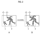
- FIG. 2 shows an example that an image processing apparatus according to a first exemplary embodiment adjusts depth of a 3D video signal.
- a difference (X, Y) in a horizontal position between the left-eye image and the right-eye image occurs when the two left and right-eye images different in a point of view with respect to one object are seen as being overlapped.
- Perspective becomes significant as the position difference between the left and right-eye images increases. Therefore, it is shown as if an object ⁇ having a great position difference Y is nearer than an object ⁇ having a small position difference X. Accordingly, the image processing apparatus in this exemplary embodiment enlarges the received 3D video signal so that the position difference Y can increase, thereby maximizing a 3D cubic effect.
- the scaler 21 of the video signal processor 20 scales the received 3D video signal through a typical scaling process to be properly displayed on the display unit 30 or to have a resolution proper for the display unit 30.
- the controller 70 selects the most optimum depth option among the depth options stored in the storage unit 60 in order to adjust the depth of the 3D video signal, and controls the scaler 21 to scale the 3D video signal to have predetermined depth on the basis of the enlargement/reduction ratio corresponding to the selected depth option stored in the storage unit 60.
- the controller 70 controls the scaler 21 to scale the 3D video signal on the basis of the enlargement/reduction ratio corresponding to the depth option selected by a user among the depth options stored in the storage unit 60.
- (A) of FIG. 2 as an example of an image corresponding to the 3D video signal received through the receiver 10, it looks as if the object ⁇ having the position difference X between the left and right-eye video signals among objects included in the image is farther back than the object ⁇ having the position difference Y between the left and right-eye video signals. In other words, it looks as if the object having the position difference Y is further front than the object ⁇ having the position difference X.
- the scaler 21 enlarges the received 3D video signal twice under the control of the controller 70, the position difference X' of the object ⁇ becomes 2 and the position difference Y' of the object ⁇ becomes 4 as shown in (B) of FIG. 2 . Due to the enlargement by the scaler 21, the enlarged position difference Y' of the object ⁇ becomes noticeably greater as compared with the enlarged position difference X' of the object ⁇ , and thus a user can more vividly feel the cubic effect.
- the image processing apparatus in this exemplary embodiment can simply achieve the adjustment of the cubic effect or depth of the 3D video signal by enlarging or reducing the 3D video signal through the scaler 21.
- FIG. 3 shows an example that an image processing apparatus according to a second exemplary embodiment adjusts depth of a 3D video signal.
- the scaler 21 of the video signal processor 20 scales the received 3D video signal to be properly displayed on the display unit 30.
- the controller 70 selects the most optimum depth option among the depth options stored in the storage unit 60 in order to adjust the depth of the 3D video signal.
- the controller 70 controls the stereoscopic information extractor 22 to extract the stereoscopic information
- the controller 70 controls the stereoscopic information extractor 22 to extract the stereoscopic information from the received 3D video signal.
- the stereoscopic information may contain information about a difference in a horizontal position between the left-eye image and the right-eye image in a predetermined area of an image corresponding to the received 3D video signal.
- the controller 70 determines an object having the most (i.e., the maximum) difference in the position of at least one object between the left and right-eye images. The determining may be accomplished by comparing the position difference information of the left and right-eye images, with regard to the at least one object included in the image corresponding to the received 3D video signal, on the basis of the position difference information extracted from the stereoscopic information extractor 22
- the controller 70 selects the object ⁇ having the large position difference Y (refer to (B) of FIG. 3 ).
- the controller 70 may control the scale ratio generator 23 to generate the enlargement or reduction ratio for enlarging or reducing only the determined object while considering the enlargement or reduction ratios stored in the storage unit 60 in accordance with the optimum depth option selected among the depth options stored in the storage unit 60 or in accordance with the option for adjusting the depth corresponding to a user's selection input through the user input unit 40.
- the controller 70 may control the scale ratio generator 23 to generate a twice enlargement ratio for the determined object ⁇ .
- the controller 70 controls the scaler 21 to enlarge only the object ⁇ on the basis of the generate enlargement ratio.
- the object ⁇ has a space Y" of 4 more enlarged twice than its original.
- the object ⁇ not determined by the controller 70 has its original space X of 1 as it is. In this case, a user more vividly feels a difference in depth between the object ⁇ and the object ⁇ .
- the image processing apparatus in this exemplary embodiment enlarges/reduces only the object determined by the controller 70 for the enlargement/reduction, so that the depth of the 3D video signal can be more deeply adjusted.
- FIG. 4 shows an example of a user interface (UI) where a depth adjusting procedure of the image processing apparatus according to the first and second exemplary embodiments is displayed.
- UI user interface
- the controller 70 controls the UI generator 50 to generate a UI 51 showing a plurality of options for adjusting the depth of the 3D image, thereby displaying the UI 51 on the display unit 30.
- the options for adjusting the depth includes the first depth option to the Nth depth option.
- the controller 70 controls the scaler 21 to scale the 3D video signal on the basis of the previously stored enlargement/reduction ratio in accordance with the selected depth option, so that an image corresponding to the scaled 3D video signal can be displayed on the display unit 30.
- the controller 70 if a user inputs a certain key for adjusting the cubic effect (or depth) of the displayed 3D image through the user input unit 40, the controller 70 enables a user to adjust the depth of the 3D video signal by using a volume control key (not shown) provided in the user input unit 40.
- the controller 70 controls the UI generator 50 to generate a UI such as the volume control in a lower side of the display unit 30 displaying the 3D image.
- the controller 70 controls the scaler 21 to enlarge a currently displayed 3D image, thereby directly displaying the scaled 3D image on the display unit 30.
- a user may input the "+” key until the 3D image having desired depth is displayed on the display unit 30.
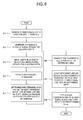
- FIGs. 5 and 6 are flowcharts of a control operation for adjusting the depth of the 3D video signal in the image processing apparatus according to the first exemplary embodiment.
- the controller 70 selects the optimum depth option among the plurality of depth options for adjusting the 3D video signal to have the optimum depth, and controls the scaler 21 to scale the 3D video signal by applying the enlargement/reduction ratio stored in the storage unit 60 in accordance with the selected depth option (S12).
- An image corresponding to the scaled 3D video signal is displayed on the display unit 30 (S13).
- the scaler 21 of the video signal processor 20 scales the received 3D video signal to be properly displayed on the display unit 30. While the 3D image corresponding to the 3D video signal scaled to be properly displayed is displayed on the display unit 30, if a certain key for adjusting the cubic effect (or depth) of the displayed 3D image is input through the user input unit 40, the controller 70 controls the UI generator 50 to generate a UI 51 showing a plurality of options for adjusting the depth, thereby displaying the UI 51 on the display unit 30 (S22).
- the controller 70 controls the scaler 21 to scale the 3D video signal on the basis of the enlargement/reduction ratio corresponding to the depth option stored in the storage unit 60 and selected by the user (S24). Then, an image corresponding to the video signal scaled to the 3D video signal having depth desired by a user is displayed on the display unit 30 (S25).
- FIGs. 7 and 8 are flowcharts of a control operation for adjusting the depth of the 3D video signal in the image processing apparatus according to the second exemplary embodiment.
- the controller 70 selects the optimum depth option among the plurality of depth options for adjusting the 3D video signal to have the optimum depth.
- the controller controls the stereoscopic information extractor 22 to extract the stereoscopic information from the 3D video signal (S32).
- the controller 70 determines a predetermined area having the most difference in a position between the left and right-eye images on the basis of the extracted stereoscopic information (S33).
- the controller 70 controls the scale ratio generator 23 to generate the enlargement or reduction ratio for enlarging or reducing the determined predetermined area (S34).
- the enlargement or reduction ratio generated by the scale ratio generator 23 may be generated with reference to the enlargement or reduction ratios previously stored in the storage unit 60 in accordance with the selected option for adjusting the depth.
- the controller 70 controls the scaler 21 to enlarge or reduce only the determined area to have the generated enlargement or reduction ratio (S35). Then, an image corresponding to the 3D video signal of which only the predetermined area is scaled is displayed on the display unit 30 (S36).
- the scaler 21 of the video signal processor 20 scales the received 3D video signal to be properly displayed on the display unit 30. While the 3D image corresponding to the 3D video signal scaled to be properly displayed is displayed on the display unit 30, if a certain key for adjusting the cubic effect (or depth) of the displayed 3D image is input through the user input unit 40, the controller 70 controls the UI generator 50 to generate a UI showing a plurality of options for adjusting the depth, thereby displaying the UI on the display unit 30 (S42).
- the controller 70 controls the stereoscopic information extractor 22 to extract the stereoscopic information from the 3D video signal (S44).
- the controller 70 determines an area having the most difference in a position between the left and right-eye images on the basis of the extracted stereoscopic information (S45).
- the controller 70 controls the scale ratio generator 23 to generate the enlargement or reduction ratio for enlarging or reducing the determined area (S46).
- the enlargement or reduction ratio generated by the scale ratio generator 23 may be generated with reference to the enlargement or reduction ratios previously stored in the storage unit 60 in accordance with the option selected by a user for adjusting the depth.
- the controller 70 controls the scaler 21 to enlarge or reduce only the determined area to have the generated enlargement or reduction ratio (S47). Then, an image corresponding to the 3D video signal of which only the predetermined area is scaled is displayed on the display unit 30(S48).
- an image processing apparatus and a control method of the same which can adjust a cubic effect of depth of a 3D video signal through the existing scaler without a separate image reconstructing device for adjusting the cubic effect or depth of the 3D video signal.
Landscapes
- Engineering & Computer Science (AREA)
- Multimedia (AREA)
- Signal Processing (AREA)
- Testing, Inspecting, Measuring Of Stereoscopic Televisions And Televisions (AREA)
- Controls And Circuits For Display Device (AREA)
Applications Claiming Priority (1)
| Application Number | Priority Date | Filing Date | Title |
|---|---|---|---|
| KR1020100056404A KR20110136414A (ko) | 2010-06-15 | 2010-06-15 | 영상처리장치 및 그 제어방법 |
Publications (2)
| Publication Number | Publication Date |
|---|---|
| EP2398244A2 true EP2398244A2 (fr) | 2011-12-21 |
| EP2398244A3 EP2398244A3 (fr) | 2014-03-26 |
Family
ID=44648326
Family Applications (1)
| Application Number | Title | Priority Date | Filing Date |
|---|---|---|---|
| EP11155110.7A Withdrawn EP2398244A3 (fr) | 2010-06-15 | 2011-02-18 | Appareil de traitement d'images et son procédé de commande |
Country Status (3)
| Country | Link |
|---|---|
| US (1) | US20110304690A1 (fr) |
| EP (1) | EP2398244A3 (fr) |
| KR (1) | KR20110136414A (fr) |
Cited By (1)
| Publication number | Priority date | Publication date | Assignee | Title |
|---|---|---|---|---|
| EP2688038A1 (fr) * | 2012-07-17 | 2014-01-22 | Samsung Electronics Co., Ltd | Procédé de mise à l'échelle de données d'image et appareil d'affichage d'image |
Families Citing this family (3)
| Publication number | Priority date | Publication date | Assignee | Title |
|---|---|---|---|---|
| KR101731343B1 (ko) * | 2010-07-14 | 2017-04-28 | 엘지전자 주식회사 | 이동 단말기 및 그 제어방법 |
| US20120300034A1 (en) * | 2011-05-23 | 2012-11-29 | Qualcomm Incorporated | Interactive user interface for stereoscopic effect adjustment |
| WO2016003165A1 (fr) * | 2014-07-01 | 2016-01-07 | 엘지전자 주식회사 | Procédé et appareil pour traiter des données de diffusion par utilisation d'un dispositif externe |
Family Cites Families (17)
| Publication number | Priority date | Publication date | Assignee | Title |
|---|---|---|---|---|
| US6215898B1 (en) * | 1997-04-15 | 2001-04-10 | Interval Research Corporation | Data processing system and method |
| US6511426B1 (en) * | 1998-06-02 | 2003-01-28 | Acuson Corporation | Medical diagnostic ultrasound system and method for versatile processing |
| JP2000078615A (ja) * | 1998-09-02 | 2000-03-14 | Sanyo Electric Co Ltd | ディジタル放送受信機 |
| US20030198290A1 (en) * | 2002-04-19 | 2003-10-23 | Dynamic Digital Depth Pty.Ltd. | Image encoding system |
| JP2004145832A (ja) * | 2002-08-29 | 2004-05-20 | Sharp Corp | コンテンツ作成装置、コンテンツ編集装置、コンテンツ再生装置、コンテンツ作成方法、コンテンツ編集方法、コンテンツ再生方法、コンテンツ作成プログラム、コンテンツ編集プログラム、および携帯通信端末 |
| US20060203085A1 (en) * | 2002-11-28 | 2006-09-14 | Seijiro Tomita | There dimensional image signal producing circuit and three-dimensional image display apparatus |
| WO2004093467A1 (fr) * | 2003-04-17 | 2004-10-28 | Sharp Kabushiki Kaisha | Dispositif de creation d'image en trois dimensions, dispositif de reproduction d'image en trois dimensions, dispositif de traitement d'image en trois dimensions, programme de traitement d'image en trois dimensions et support d'enregistrement contenant ce programme |
| US8208013B2 (en) * | 2007-03-23 | 2012-06-26 | Honeywell International Inc. | User-adjustable three-dimensional display system and method |
| GB0708676D0 (en) * | 2007-05-04 | 2007-06-13 | Imec Inter Uni Micro Electr | A Method for real-time/on-line performing of multi view multimedia applications |
| JP2010088092A (ja) * | 2008-09-02 | 2010-04-15 | Panasonic Corp | 立体映像伝送システム、映像表示装置および映像出力装置 |
| US8606076B2 (en) * | 2008-11-24 | 2013-12-10 | Koninklijke Philips N.V. | 3D video reproduction matching the output format to the 3D processing ability of a display |
| BRPI1005691B1 (pt) * | 2009-02-17 | 2021-03-09 | Koninklijke Philips N.V. | método de combinação de dados de imagem tridimensional [3d] e dados gráficos auxiliares, portador de informações compreendendo dados de imagem tridimensional [3d] e dados gráficos auxiliares, dispositivo de geração de 3d para combinar dados de imagem tridimensional [3d] e dados gráficos auxiliares, dispositivo de exibição em 3d para combinar dados de imagem tridimensional [3d] e dados gráficos auxiliares |
| JP5469911B2 (ja) * | 2009-04-22 | 2014-04-16 | ソニー株式会社 | 送信装置および立体画像データの送信方法 |
| WO2010143439A1 (fr) * | 2009-06-12 | 2010-12-16 | パナソニック株式会社 | Dispositif de reproduction, circuit intégré et support d'enregistrement |
| US20110093888A1 (en) * | 2009-10-21 | 2011-04-21 | John Araki | User selection interface for interactive digital television |
| EP2334088A1 (fr) * | 2009-12-14 | 2011-06-15 | Koninklijke Philips Electronics N.V. | Génération d'un signal vidéo 3D |
| KR101759943B1 (ko) * | 2010-01-11 | 2017-07-20 | 엘지전자 주식회사 | 방송 수신기 및 3d 이미지 디스플레이 방법 |
-
2010
- 2010-06-15 KR KR1020100056404A patent/KR20110136414A/ko not_active Withdrawn
- 2010-12-06 US US12/960,618 patent/US20110304690A1/en not_active Abandoned
-
2011
- 2011-02-18 EP EP11155110.7A patent/EP2398244A3/fr not_active Withdrawn
Non-Patent Citations (1)
| Title |
|---|
| None |
Cited By (1)
| Publication number | Priority date | Publication date | Assignee | Title |
|---|---|---|---|---|
| EP2688038A1 (fr) * | 2012-07-17 | 2014-01-22 | Samsung Electronics Co., Ltd | Procédé de mise à l'échelle de données d'image et appareil d'affichage d'image |
Also Published As
| Publication number | Publication date |
|---|---|
| EP2398244A3 (fr) | 2014-03-26 |
| US20110304690A1 (en) | 2011-12-15 |
| KR20110136414A (ko) | 2011-12-21 |
Similar Documents
| Publication | Publication Date | Title |
|---|---|---|
| US9307224B2 (en) | GUI providing method, and display apparatus and 3D image providing system using the same | |
| US10154243B2 (en) | Method and apparatus for customizing 3-dimensional effects of stereo content | |
| US9414041B2 (en) | Method for changing play mode, method for changing display mode, and display apparatus and 3D image providing system using the same | |
| US8872901B2 (en) | Stereoscopic glasses and display apparatus including the same | |
| CN104219515B (zh) | 图像处理装置 | |
| US20150350626A1 (en) | Method for providing three-dimensional (3d) image, method for converting 3d message, graphical user interface (gui) providing method related to 3d image, and 3d display apparatus and system for providing 3d image | |
| US20110126160A1 (en) | Method of providing 3d image and 3d display apparatus using the same | |
| KR101287786B1 (ko) | 3차원 입체영상 표시 방법 및 그를 이용한 영상 표시 장치 | |
| US20110010666A1 (en) | Method for displaying three-dimensional user interface | |
| KR20120055991A (ko) | 영상처리장치 및 그 제어방법 | |
| US8767052B2 (en) | Remote controller, display apparatus, 3D glasses and control method thereof | |
| CN102387394B (zh) | 显示装置及其图像生成方法 | |
| EP2398244A2 (fr) | Appareil de traitement d'images et son procédé de commande | |
| US20110115789A1 (en) | Image displaying apparatus and image signal processing method of the same | |
| KR20110111136A (ko) | 음향 설정에 대응하는 3d 오브젝트를 제공하는 영상표시장치 및 그 동작 제어방법 | |
| KR20130094905A (ko) | 디스플레이장치 및 그 입체감 조정방법 | |
| US20120069155A1 (en) | Display apparatus and method for processing image thereof | |
| KR20120027817A (ko) | 영상표시장치 및 그 동작방법 | |
| US8736602B2 (en) | Display apparatus and control method thereof | |
| KR20110062983A (ko) | 3d 영상의 입체감 조절 요소를 설정하는 gui를 표시하는 디스플레이 장치 및 이에 적용되는 gui 제공 방법 | |
| KR20140124263A (ko) | 디스플레이장치 및 디스플레이장치의 3d 효과 설정 방법 |
Legal Events
| Date | Code | Title | Description |
|---|---|---|---|
| AK | Designated contracting states |
Kind code of ref document: A2 Designated state(s): AL AT BE BG CH CY CZ DE DK EE ES FI FR GB GR HR HU IE IS IT LI LT LU LV MC MK MT NL NO PL PT RO RS SE SI SK SM TR |
|
| AX | Request for extension of the european patent |
Extension state: BA ME |
|
| PUAI | Public reference made under article 153(3) epc to a published international application that has entered the european phase |
Free format text: ORIGINAL CODE: 0009012 |
|
| RAP1 | Party data changed (applicant data changed or rights of an application transferred) |
Owner name: SAMSUNG ELECTRONICS CO., LTD. |
|
| PUAL | Search report despatched |
Free format text: ORIGINAL CODE: 0009013 |
|
| AK | Designated contracting states |
Kind code of ref document: A3 Designated state(s): AL AT BE BG CH CY CZ DE DK EE ES FI FR GB GR HR HU IE IS IT LI LT LU LV MC MK MT NL NO PL PT RO RS SE SI SK SM TR |
|
| AX | Request for extension of the european patent |
Extension state: BA ME |
|
| RIC1 | Information provided on ipc code assigned before grant |
Ipc: H04N 13/00 20060101AFI20140217BHEP |
|
| STAA | Information on the status of an ep patent application or granted ep patent |
Free format text: STATUS: THE APPLICATION IS DEEMED TO BE WITHDRAWN |
|
| 18D | Application deemed to be withdrawn |
Effective date: 20140927 |